AMAZON multi-meters discounts AMAZON oscilloscope discounts
(cont. from part 3)
31. WIRING DEVICES: SPECIALTIES
The most common device in this group, which also includes pilot lights, fan controls, and other small motor controls, is the lighting dimmer. The original lighting dimmers were variable autotransformers.
They were large, heavy, and expensive, and there fore found application mainly in theater lighting, displays, and the like. The advent of small electronic units (SCRs) made the modern wall-box dimmer possible. The simplest units are rotary, with limited capacity and applicable only to incandescent lamp loads. One of their disadvantages, still found in inexpensive units, is the production of annoying radio frequency interference (RFI) and line harmonics.
Newer models are available that provide preset control, combine dimming and switching, are usable for smooth fan speed control, can be remotely controlled (in addition to local control), provide automatic fadeout, and can dim fluorescent lamps (provided with dimming ballasts). A few types are shown in Figs. 26.49 and 26.50.
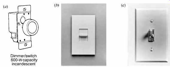
Fig. 49 (a) Simple solid-state dimmer, suitable for a maximum 600-W incandescent
load only. The switch permits level preset in a pushbutton design. Inexpensive
units may cause considerable radio frequency interference (RFI). (b) Slide
dimmer for a 600-W incandescent load, including on-off and level preset. This
dimmer is available with a wireless receiver that responds to a handheld infrared
remote control. (c) Combined on-off switch and slide dimmer provides preset
level control. Units similar to (b) and (c) are available for loads of up to
1000 W, fluorescent lamp control (with appropriate ballast), and fan speed
control. (Photos b and c courtesy of Lutron Electronics Co., Inc.)
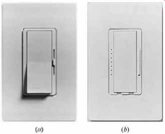
Fig. 50 (a) Combined tap switch and slide dimmer provides preset level control.
A built-in night-light suggests a residential application. (b) Multifunction
tap switch in the center permits switching to full brightness, gradual brightening
to preset, 10-second fade-out, and off. Rocker switch at the right controls
levels. LEDs behind pinholes at the left provide an indication of the preset
level. Both illustrated unit designs are available for incandescent and fluorescent
(with special ballast) lamp control and fan speed control. Both are designed
with RFI suppression. (Photos courtesy of Lutron Electronics Co., Inc.)
32. LOW-VOLTAGE SWITCHING
The switches illustrated and discussed in Section 30 are all full-voltage types; that is, they are wired directly into the load circuit and operate at line voltage and full current. A control scheme that uses light-duty, low-voltage (24-V) switches to control line voltage relays, which in turn do the actual circuit switching, is illustrated in Figs. 26.51 and 26.52. The system is variously referred to as low-voltage switching, remote-control switching, and low-voltage control.
Because the loads in this system are relay controlled, any number of switches and control devices can be wired in parallel to operate a relay and thereby effect the switching. Thus, the control can be local, remote, and master, with individual override by local control devices such as occupancy sensors, and central control or override at a central controller by timers, daylight controllers, and so on.
The advantages of this system of control over full voltage switching are:
• Flexibility of control location
• Individual load control override by local control devices (occupancy sensors, photocells; see Section 15.15)
• Group load override by central control devices such as timers, daylight controllers, and energy management systems
• Low cost of low-voltage, low-current wiring compared to full-voltage wire and conduit
• Inherent system flexibility and simplification of alterations
• Monitoring of the status of individual loads at a centralized control panel by the use of relays with auxiliary contacts (see Fig. 51) The second and third points are particularly important from an energy conservation perspective, as it has been amply demonstrated that reliance on manual controls to limit energy usage yields disappointing results.
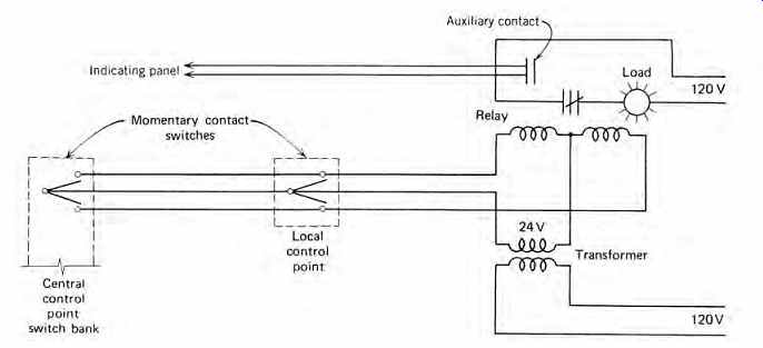
Fig. 51 Low-voltage switching control. Multipoint control and central control
are illustrated. The diagram shows the relays located at the load. Central
relay cabinets are used in dense load areas.
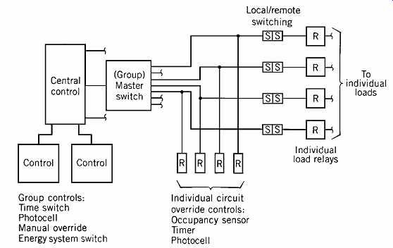
Fig. 52 Schematic arrangement of a large low-voltage switching system. Individual
loads can be switch-controlled from multiple locations, including a group (master)
control point. In addition, local control devices such as photocells and occupancy
sensors can override the local switches to maximize energy conservation. Central
(group) control devices can perform the same override function at the group
level.
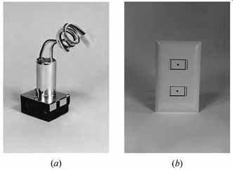
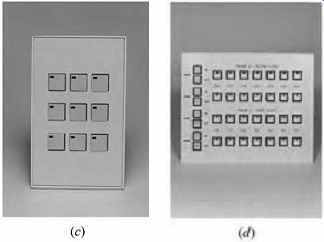
Fig. 53 Components of low-voltage switching and control systems for lighting
and other electric loads. (a) The basic switching device is a single-pole,
double-throw latching relay with a 24-V coil and 20-A, 120-277-V contacts.
It is shown with a plug-in connector on its leads, making it suitable for rapid
mounting in a relay panel (see Fig. 54). The same relay without the connector
is suitable for hard-wiring at a controlled device. (b) Low-voltage (24-V)
wall switches can be mounted singly or ganged in groups of two to eight switches.
Switches are available in button, rocker, key-operated, and lighted designs
(as in b-d). (c) Switching station with pushbutton low-voltage switches, each
with an LED to indicate switch position (on-off). (d) Switch bank with illuminated
pushbutton switches identified with room number and floor. The on-off switches
at the left of the bank are override switches for the corresponding horizontal
line. (Photos courtesy of Touchplate Technologies, Inc.)
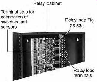
Fig. 54 Prewired relay cabinet (partial). Field wiring consists of control
wiring to switches and sensors and power wiring to the controlled loads. (Photo
courtesy of Touchplate Technologies, Inc.)
The basic components of the entire system are the control relay and the switches, shown in Fig. 53. Small systems use hard wiring (physically wired connections), with the hard-wired relays installed either dispersed at each controlled fixture (or lighting group) or grouped in a relay panel.
When the number of relays exceeds about 20, these panels become so densely wired that control changes become difficult and tedious. As a result, prewired computer- or microprocessor-controlled panels are used in large systems, where connections can be made and changed easily. The interior of one such panel is shown in Fig. 54. The logic of a medium-sized computer-controlled system is shown in Fig. 55. Manufacturers have made software available that permits rapid, accurate design of complex, large systems. A typical computer screen in such a system is shown in Fig. 56.
33. WIRELESS SWITCHING AND CONTROL
Full-voltage local switching was described in Section 30, and low-voltage switching, both local and remote, was described in Section 32. The next logical step is remote wireless control and switching. These systems have undergone extensive development. They impinge on the design considerations of architects and building engineers to the extent that facilities to accommodate such systems must be provided if such controls are to be used in a facility.
Aspects of wireless control and switching, as well as system functioning and application to lighting control, are discussed in detail in Section 15.
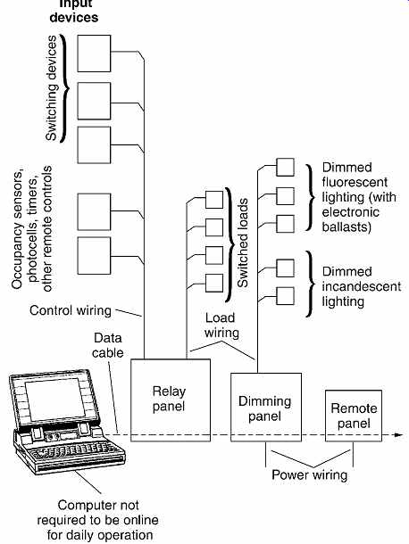
Fig. 55 Block diagram of a large, computer-controlled, low-voltage control
system. The relay panel contains the incoming and outgoing power and control
wiring, the switching relays, and the computer interface card. The system arrangement
is controlled by computer software. (Courtesy of Touchplate Technologies, Inc.)
34. POWER LINE CARRIER SYSTEMS
Although the advantages inherent in flexible, programmable load-switching systems such as those described in the preceding sections are undeniable, particularly in connection with energy management systems, their high first cost frequently makes their use uneconomical. This is particularly true when retrofitting large, complex facilities with energy management controls, where the cost of wiring, even when using low-voltage control wires, can amount to more than half of the total cost of the project.
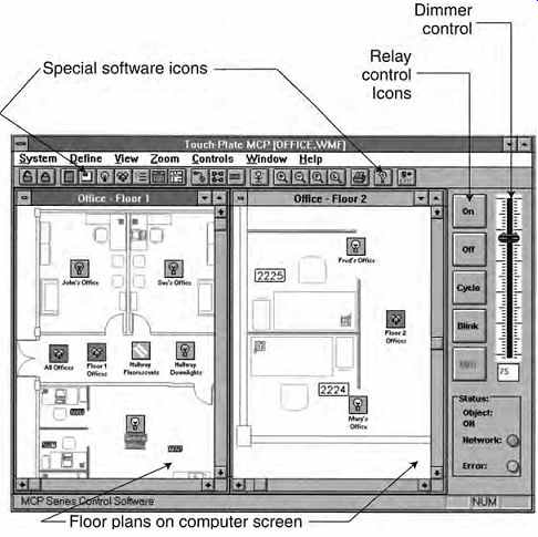
Fig. 56 Typical computer screen of low-voltage control software showing facility
floor plans (scanned in) and controlled loads. The icons at the top of the
screen are customized and are used to control relays, make connections, check
status, print, and log events by time and date. Other screens enable group
and event definition, labeling, establishment of priorities, and other global
sequential and individual control functions. (Courtesy of Touchplate Technologies,
Inc.)
To minimize control wiring costs, a system of control signal transmission that uses the electric power wiring (either new or existing) to conduct signals was developed, thus removing the need and expense for dedicated control wiring. This system is called a power line carrier (PLC) system because the power line carries the control signal. An ancillary benefit of such an arrangement is that not only can it be added to an existing system, it can also be easily removed, thus making possible and economical the leasing of energy management control systems.
The system operates by injecting into the power wiring a series of low-voltage, high-frequency, binary-coded control signals, which then disperse over the entire power network. Only a receiver that is "tuned" to receive a particular code reacts, generally by operating a local device, which in turn connects, disconnects, dims, or brightens a particular load. In practice, the control signal generator can be a small, manually programmed controller, as in a residence, or a computer-operated energy management or lighting controller in a commercial facility. The receivers are normally of four types, most of which are designed to fit into an ordinary wiring device box:
1. A wall-switch module, which acts as a normal manual wall light switch but also contains a coded receiver and a fully rated relay (20 A, 125 V, or 277 V)
2. A wall receptacle module, which contains a 20-A receptacle along with a receiver and relay that serve to switch power on and off
3. A switching module, which can be connected to activate contactors, small motors, and the like 4. A dimming module, which provides both local and remote control Some of these components are shown in Fig. 57. Larger, multiple-circuit switching modules are also available for more extensive systems.
Each miniature receiver can be manually tuned in the field (i.e., its code can be set and reset readily), giving the entire system extreme flexibility.
The system operates in the same manner as a low-voltage switching system or an energy management or lighting control system, with the essential difference that no dedicated control wiring is required. In retrofit jobs, existing wall switches and receptacle outlets are replaced with receiver controlled units; in new installations, these devices are installed initially.
Due to the fact that the control signals travel over the power wiring and are therefore attenuated by high-resistance connections, poor grounds, and faulty wire insulation, PLC installations require a high-quality power wiring installation to operate properly. In retrofit work, preliminary tests occasionally indicate the impracticability of a PLC installation because of the condition of the power wiring system. Another problem encountered in PLC systems is interference with the PLC control signals from radio noise generated by faulty power equipment and by improperly shielded or grounded electronic equipment. These problems can frequently be overcome by careful testing, installation of filters and jumpers, and repair of improperly operating equipment. In addition to energy management and normal lighting control, PLC control can be applied to group switching of other loads, such as office machines, in addition to simplifying control of temporary light and power for special events.
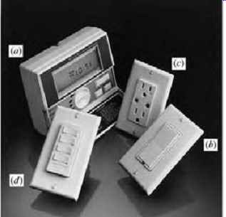
Fig. 57 Components of a residential-type PLC system. (a)
Control unit, at which both manual and automatic (programmed)
control of a maximum of 256 address codes is possible. (b)
Wall-switch module has local dimming and switching functions in addition to being remotely controlled from the control center (a). (c) Duplex wall receptacle, either split-wired with local programming of one-half of the outlet or complete remote control.
(d) Outlet box wall-mounted control switch that provides local group control (switching and/or dimming) for one to four devices (address codes). (Photo courtesy of Leviton Manufacturing Co.)
35. POWER CONDITIONING
(a) General Information
Power conditioning is a relatively new electrical term that describes the process of converting utility-supplied electrical power, which is frequently characterized by transient surges, spikes, radio frequency noise, and voltage fluctuation, to a pure (noiseless), accurately voltage-regulated sinusoidal waveform, normally referred to as computer-grade power.
Some form of power conditioning is required by all data-processing and telecommunication equipment and by many other types of electronic equipment. This is due to their extreme sensitivity to fluctuations in the power supply voltage and particularly to random high-frequency voltages superimposed on the power supply voltage, known as radio frequency interference (RFI) or simply radio noise. In the case of data-processing equipment (computers and peripherals), radio noise can cause data errors; slow voltage fluctuations can cause overheating, data loss, and premature equipment failures; and large, rapid voltage fluctuations (spikes, transients) can cause equipment burnout and system collapse.
The economic ramifications of such effects on large commercial data-handling systems are so severe that power conditioning has become almost universal. (Power conditioners must not be confused with uninterruptible power supplies [UPS], which function to maintain power during utility failure, although in many commercial installations, both functions are served by a single equipment pack age.) (b) Source of Disturbance
Utility power systems are designed to maintain volt age and frequency within certain limits on an aver age, long-term basis. For valid technical reasons, utility equipment cannot react to the short-time disturbances that are so inimical to electronic equipment. Furthermore, much of the noise in utility lines is introduced by users and is therefore beyond the utility's point of control. Disturbances on the electrical power line can roughly be classified into three types: voltage variations, electrical noise, and transients.
1. Voltage variations. These can be caused by short-time current drain, such as during motor starts, deliberate voltage reductions (brownouts), load switching of EMS systems, excessive line volt age drop due to heavy loading or current leakage, and similar problems. These variations are relatively slow and long-lasting.
2. Electrical noise. This is a low-amplitude, higher-frequency voltage that, when superimposed on the power line, results in a distorted waveform.
Sources of such extraneous voltages are electronic equipment power supplies, lighting dimmers, solid-state motor controls, PLC systems, arc welding, switching transients caused by branch circuit switches and relays, and voltages induced by local magnetic fields.
3. Transients. These are large, short-duration voltage variations, also known as surges or spikes.
They are the principal culprits in major equipment failures. They are caused by lightning strikes to overhead lines (possibly many miles from an affected installation), by electrical system faults, and by utility switching of high-voltage lines, transformers, capacitor banks, generators, and circuit reclosers.
36. POWER-CONDITIONING EQUIPMENT
Each of the three types of problems described in the preceding section requires its own type of correction. Voltage variations are corrected with voltage regulators; noise problems are corrected by electrical isolation, filtering, and noise suppression; and transients are treated with surge suppressors. Each corrective device is a separate entity that can be applied individually to suit the particular problem encountered or in combination with another conditioning device. The choice in a specific installation is a highly technical decision and should be made by the facility's electrical engineer after careful analysis of the quality of the utility service. A few general recommendations can be made.
1. All computer installations, including the smallest, should be protected from line transients with an appropriate surge suppressor. Multitap plug-in strips (low-cost) with integral surge suppressors are unsatisfactory unless they have surge current, clamping voltage, and surge-energy specifications, and these meet the installation requirements.
2. Major data-processing installations normally require all three types of line treatment. The most economical way to provide them is with a single integrated power-conditioning unit.
3. Considerable improvement in the quality of electrical power can frequently be achieved by the simple expedient of running separate electrical feeders for sensitive loads.
4. Physical isolation of sensitive equipment areas is frequently helpful, particularly when disturbances are being induced by proximity to switching, arcing, and rectifying equipment. Discharge-type lighting, including fluorescent, mercury, sodium vapor, and metal-halide, can cause interference, especially when used with electronic ballasts.
5. It was found some years ago that much of the noise in electrical power systems was introduced through the (equipment) grounding pole of an electrical receptacle. Because this connection is required for electrical safety, it cannot be eliminated. It can, however, be separated from the wiring system ground and still maintain its function.
Receptacles so constructed are color-coded either entirely orange or have an orange triangle on the face (see Section 29). This "fix" is particularly effective where electronic dimmers, ballasts, and switching devices are present. Because the insulated ground receptacle (sometimes referred to as an isolated ground receptacle) is a special item, it must be clearly indicated in the contract documents (drawings and specifications). Furthermore, because these receptacles require special isolated wiring, the entire matter must be studied carefully during the electrical design stage and before issuance of construction contracts.
6. A problem related to equipment that produces radio noise is that this same equipment also produces harmonics that appear on the system neutral and can cause overloading. This subject is covered in Section 28.18.
The issue of power quality is so important in modern commercial installations that the following steps should be taken essentially as a matter of course during design:
• A detailed report should be obtained from the electric utility that will be supplying electric power, showing power outages, voltage constancy, frequency control, and, if possible, oscillograms of waveforms at random intervals over the past year. Particularly important are periods of peak loading and periods of weather extremes.
• A power-quality study should be made in the area in which the facility will be (or is) located.
Sophisticated instrumentation for this purpose as well as specialists in this field are readily avail able (see Sections 26.35 and 26.36).
• An in-depth study of all of the electrical equipment to be used in the building should be made for the purpose of:
• Reducing the sources of electrical disturbances
• Determining the tolerance or sensitivity of the data-processing equipment to be used. In the absence of reliable data for the second purpose, as is the case in speculative construction, a high degree of sensitivity should be assumed. In any case, for equipment that is known to produce radio noise, such as electronic lighting ballasts and dimmers, the specifications should include limitations plus a requirement for submission of laboratory tests on random samples.
• Many large power companies now offer "computer-grade power" that meets stated limitations to voltage fluctuation and the like. This type of service is desirable for all new office space or full building renovations. For individual office spaces, separate power-conditioning equipment is required.
Table 7 and Fig. 58 give some idea of the physical characteristics of power-conditioning equipment. Dimensions are typical and are indicative only of equipment bulk. Designs vary widely among manufacturers, as do, therefore, individual dimensions. Voltage-regulating equipment containing regulating transformers is very heavy, and this must be considered during design. Power conditioning equipment is frequently combined with UPS equipment (see Section 38).
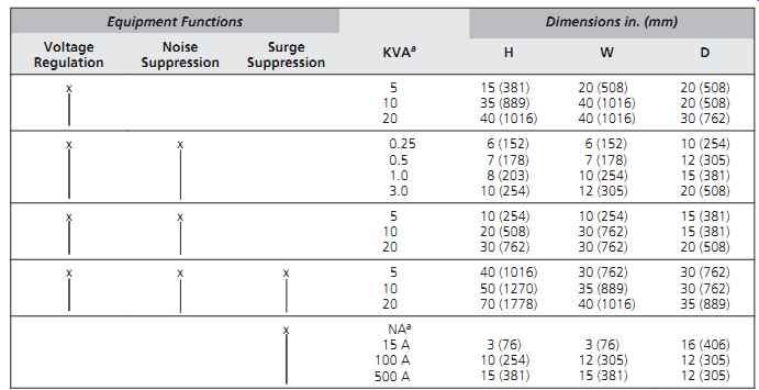
TABLE 7 Power-Conditioning Equipment
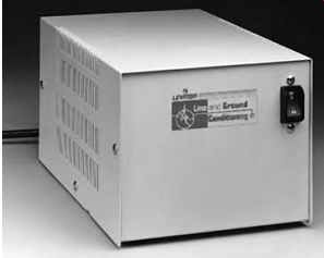
Fig. 58 This single-phase power conditioner supplies noise filtering and surge
suppression by use of an isolation trans former, ground noise filters, and
category A and B surge suppression (see Section 37c). It is rated 5 A, 120
V, measures 6 in. H × 7 in. W × 11 in. D (150 × 180 × 280 mm), and weighs 18
lb (8 kg). A similar unit rated 20 A, 120 V measures 8 in. H × 8½ in. W × 14
in. D (200 × 215 × 355 mm). (Photo courtesy of Leviton Manufacturing Co.)
37. SURGE SUPPRESSION
The full term for this aspect of power conditioning is transient voltage surge suppression (TVSS). Because transient voltages, also called surges or spikes, can cause major physical damage to computer systems and other types of electronic equipment, it is this aspect of system protection that has generally received the most attention (including a fair amount of highly imaginative advertising). Surge suppressors are available in a wide variety of designs and ratings, ranging from the ubiquitous cord-connected, multiple-outlet strip to large, 3-phase, service-entrance units. They all have a single purpose, however: to suppress (limit) a voltage surge to a level that the protected equipment can withstand without damage. This is done in two ways:
1. By placing one or more devices that present a high impedance in series with the incoming voltage transient, thereby limiting the let-through current.
2. By placing one or more devices across the incoming power line, in parallel with the protected load, that present a low impedance to the high transient voltage and thereby bypass (shunt away) the incoming disturbance's current. Many TVSS units use both of these techniques in a single "hybrid" unit.
(a) Terminology
To be able to select TVSS units and compare their ratings, a basic technical vocabulary is necessary.
Avalanche diode. A solid-state device placed in parallel with a protected load. It responds to over voltage in nanoseconds by conducting (i.e., placing) its very low impedance across the incoming voltage.
This results in a large ("avalanche") bypass current flow that serves to reduce the incoming voltage. It has a low clamping voltage (definition follows) and low energy absorption capacity. This latter characteristic causes "wear" and eventual failure.
Clamping voltage. The voltage at which a shunting device (such as an avalanche diode) begins to conduct (and thereby clamp) an incoming voltage surge. The lower a device's clamping voltage, the better its suppression action.
EMI/RFI rejection. A measure of the attenuation, by a TVSS device, of electromagnetic interference (EMI) and RFI. A TVSS device, due to its internal filters, always provides some radio noise attenuation.
This characteristic is not of primary significance to selection of a device used primarily for surge suppression.
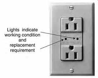
Fig. 62 Typical category A utilization TVSS outlet equipped with indicating
lights that show the condition of the surge suppressor circuitry. (Photo courtesy
of Eagle Electric Co.)
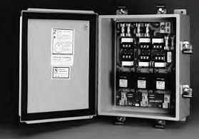
Fig. 60 Surge suppressor designed for use on the incoming service of a facility.
It is rated for category C3 application: shunt type, 120/208 V, 3-phase, unlimited
current. It is provided with RFI/EMI filtering and replaceable surge-suppressor
modules, and arranged to indicate the power and protection status of each phase.
(Photo courtesy of Surge Control Ltd.)
Gas tube surge protector. A high-energy shunt device, typically found in high-capacity, good-quality TVSS units that are subject to large surges (such as those caused by lightning). It consists of a gas-filled tube with two electrodes. The tube conducts when a high-voltage surge causes its electrodes to arc over.
Because of low arc impedance, the current drain and energy absorption are very high, thus clamping the incoming surge. Its principal drawback is its relatively slow response, which necessitates its use in conjunction with other, faster devices.
Isolation transformer. A transformer with two separate windings and no conductive electrical connection between them. By virtue of the inductive coupling of the windings, considerable attenuation of sharp voltage spikes is achieved. It can be used in high-capacity TVSS units in lieu of multiple solid state components in parallel. It is also useful in attenuating high-frequency noise at any voltage level.
Joule rating. A joule, equal to 1 watt-second, is the SI unit of energy. A device's joule rating is a measure of its capacity to absorb and dissipate heat generated by its action. Although the joule rating is important where large amounts of energy are to be absorbed, as in (hard-wired) units at a service entrance or at a power distribution point, published ratings can be misleading because there is, at this writing, no industry-wide standard calculation procedure for joule rating. As a result, the industry standard specification form (NEMA-LS 1) for TVSS devices does not include this rating.
Maximum surge current. A measure of a device's ability to divert and dissipate surge current without failing. It is a useful metric for TVSS devices used at service entrances and, for reasons explained previously, is more reliable than published joule ratings.
Metal-oxide variable resistor (MOV). A shunt device somewhat slower than an avalanche diode but with much higher energy absorption capability and higher clamping voltage. MOVs are very widely used in TVSS devices. Like avalanche diodes, MOVs suffer degradation with use, thus limiting the useful life of the entire TVSS unit.
Response time. A measure of the rapidity with which a TVSS device begins to clamp a voltage surge, usually measured in microseconds or nanoseconds. It is not of great significance because both avalanche diodes and MOVs (found in all good grade TVSS designs) are faster than the voltage buildup time of an incoming surge. Response time is not included in the NEMA standard specification, apparently because it is not considered to be a very important characteristic.
Sinewave tracking. A term of uncertain meaning found frequently in manufacturers' literature.
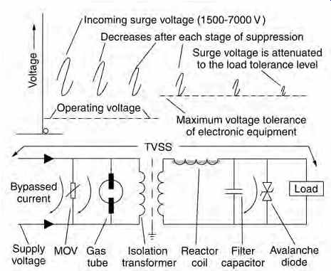
Fig. 59 All of the elements usually found in a surge-suppression device are
shown. Each acts to reduce voltage surge-parallel elements by shunting away
(bypassing) surge current, and series elements by increasing the electrical
impedance to the voltage surge.
(b) TVSS Operation
Figure 59 is intended to be self-explanatory.
Each element acts to reduce the magnitude of the incoming voltage surge by either bypassing (shunting away) current or presenting a high impedance to the voltage surge. Both actions reduce the volt age. A commercial TVSS device may contain any or all of the illustrated components, single or in multiple, depending upon the current and voltage it is expected to handle.
(c) Standards
Standards applicable to surge-suppression equipment are:
ANSI/IEEE C62.41.1: IEEE Guide on the Surges Environment in Low-Voltage (1000 V and Less) AC Power Circuits ANSI/IEEE C62.45: IEEE Recommended Practice on Surge Testing for Equipment Connected to Low Voltage (1000 V and Less) AC Power Circuits UL 1449: Standard for Surge Protective Devices NEMA LS 1: Low Voltage Surge Protection Devices Surge-suppression equipment can be subjected to widely varied voltage stresses, depending upon where in an electrical system a unit is installed.
Standard C62.41 categorizes installation points according to the severity of service expected, that is, the (electrical) environment in which the surge suppression equipment operates.
C62.41, category C represents the most severe environment, corresponding to locations on the line side of the facility service switches. This environment is subject to the full force of lightning and switching surges and requires robust equipment. As a voltage surge travels through a building's electrical system, it is attenuated by cables, transformers, and other electrical equipment. Therefore, the further along one travels in the building's electrical distribution system, the less severe the voltage surges become. All TVSS devices used in category C environments are hard-wired (Fig. 60).
C62.41, category B covers environments on the load side of the service equipment, including heavy feeder distribution panels and short branch circuits. Most TVSS devices in category B areas are hard-wired (Fig. 61).
C62.41, category A, which represents the least severe service, includes utilization outlets and long branch circuits (because the long cables attenuate a voltage surge). Most category A TVSS devices are arranged for loads to be plugged in directly. Devices used in category A environments include the common cord-connected multi-outlet strip and surge suppression- equipped receptacles (Fig. 62).
Each of these three major categories is in turn subdivided into three minor categories: C3, C2, C1; B3, B2, B1; and A3, A2, and A1-where 3 is the most severe and 1 the least. The differentiation depends upon the electrical capacity of the facility's service and distribution system. Large systems have higher surges and less attenuation in the system, thus requiring larger and heavier TVSS equipment than smaller installations. The three major categories are shown graphically with annotations in Fig. 63.
Standard C62.45 established the test procedures and test voltage levels to be used by manufacturers in testing and classifying their TVSS products in order to simulate the voltage stresses found in A, B, and C environments.
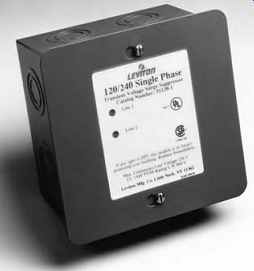
Fig. 61 TVSS unit designed to be used at service and branch panelboards in
residences and small commercial installations.
The illustrated unit is rated single-phase, 120/240 V, 3-wire ser vice, category B3. The unit measures 7 in. W × 7 in. H × 4 in. D (180 × 180 × 100 mm) and is equipped with indicating lights that note power and suppression status. (Photo courtesy of Leviton Manufacturing Co.)
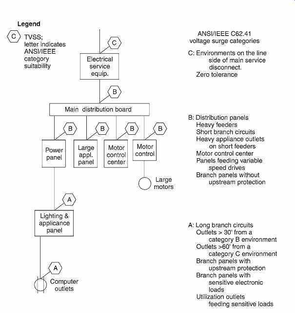
Fig. 63 Illustration based on ANSI/IEEE Standard C62.41 showing application
of transient voltage-suppression devices in a typical electrical facility,
based on the three categories of electrical environments (C, B, A) defined
by the standard.
UL Standard 1449 describes standards for surge-suppressor safety and performance. An important aspect of this standard is that it establishes clamping voltage ratings. The ones of interest to building designers are the lowest four, which are 330, 400, 500, and 600 V. The UL standard requires testing for actual clamping levels, which are then rounded upward to one of the standard ratings. Thus, a TVSS that clamps at 240 V and one that clamps at 320 V would both be rated at 330 V, despite the fact that the 240-V unit gives better protection. This distinction is particularly important when protecting computers and other electronic equipment equipped with switching power supplies, and requires a comparison of the actual clamping voltage of potential devices rather than simple reliance on the voltage classification.
NEMA LS 1 standardizes the specification for mat for suppression units, and in so doing establishes a basis for comparison among various manufacturers' products. Important characteristics that must be specified include line voltage, maximum operating current and voltage, maximum surge current, and clamping voltage rating. (Actual clamping voltage is not supplied unless specifically requested, as it involves specific testing.) All of the aforementioned standards are voluntary industry and technical society publications. In 1997, the U.S. government developed a Performance Verification Test specification that established a quality grading system for cord-connected surge suppressors. This standard does not correspond readily to the C62.41 classifications, except in the B category. It is worth noting that the highest classification in this system is Class 1, Grade A, Mode 1, which corresponds to ANSI category B3, a UL 1449 clamping voltage rating of 330 V, and line to neutral protection.
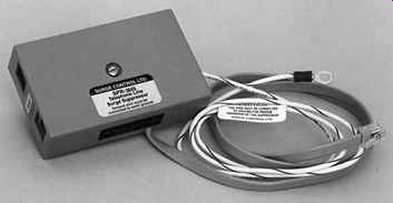
Fig. 64 Surge suppressor designed for use with standard snap-in low-voltage
telephone and industry jacks. The illustrated unit is designed to protect telephone/telecommunication
lines, both analog and digital. The units are rated 185 V, with a maximum surge
cur rent of 5000 A and a test clamping voltage of 240 V. The units can be used
with telephones, modems, fax machines, and the like. They measure approximately
4 in. W × 2½ in. H × 1 in. D (100 × 64 × 25 mm). (Photo courtesy of Surge Control
Ltd.)
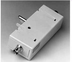
Fig. 65 TVSS device designed to protect video lines from volt age transients.
The unit plugs into a standard outlet to establish a ground connection for
current bypass. This unit is equipped with BNC (Bayonet Neill-Concelman) connections;
others have telephone, PL (coaxial), and RS (serial device) connectors for
use on telephone, communication, and data lines. The illustrated unit has a
clamping voltage of 15 V and a maximum surge current capacity of 5000 A. It
measures approximately 2 in. W × 4 in. H × 1 in. D (50 × 100 × 25 mm). (Photo
courtesy of Leviton Manufacturing Co.)
(d) Application of TVSS Devices
Selection and application of surge-suppression de vices for even the simplest application requires considerable technical background, for which the foregoing material is intended as a primer. Important suggestions to assist in this area are:
• Every power level should have its own TVSS. Small systems can function with C62.41 categories B and A only. Large systems may require protection for two or three B levels (B3, B2, B1) and more than one A level.
• In the absence of accurate data on the surge tolerance of electronic equipment, use protection for the most sensitive level. At the utilization level, this is category A3 and U.S. government classification Grade A, Class 1, Mode 1.
• Mode 1 (also called Mode A) indicates protection line-to-line or line-to-neutral. This mode should be specified for stand-alone items. It is preferable to Mode 2 (or B), which is connected line-to-ground, because the latter can introduce random signals (contaminants) into the equipment-grounding system.
• The primary criteria for selection and comparison are the actual clamping voltage and maxi mum surge current capacity. Other important characteristics are those listed in NEMA LS 1.
• TVSS units should be installed as close as possible to the loads being protected.
• Telephone and data lines must also be protected, particularly if the service is overhead. Most telephone companies install an appropriate TVSS at the main distribution frame near the service entrance. This may not be sufficient to protect electronic equipment from a disturbance that can cause distortion of data. A specialist should be consulted to determine the required protection levels and select appropriate equipment (Figs. 26.64 and 26.65).
38. UNINTERRUPTIBLE POWER SUPPLY
As explained previously, power-conditioning equipment can supply clean utility power; it cannot, however, supply any power during a utility out age. That eventuality is addressed by providing an alternate supply of power. Facilities with desk top computers, servers, and other data-processing equipment cannot tolerate power outages in excess of about 8 to 50 milliseconds (ms) without serious risk of data loss, and all the negative ramifications of such a loss.
An uninterruptible power supply (UPS) is an arrangement of normal and backup power supplies that transfer a facility's critical load from the normal to the backup supply in so short a time that no computer malfunction results. This transfer time varies somewhat among different schemes and manufacturers but is always less than 8.3 ms, which is the minimum period of power outage that computers must tolerate without disturbance to meet the computer industry's manufacturing guidelines.
This time period is double the maximum transfer time required by IEEE Standard 446, Recommended Practice for Emergency and Standby Power Systems for Industrial and Commercial Applications, of ¼ cycle at 60 Hz, or 4.16 ms. Thus, all computer systems fed from a UPS that meets this standard have a safety factor of at least 2 with respect to transfer time.
The period of time after transfer that the equipment will run on the standby source depends upon system design. In most cases it is 5 to 10 minutes, which is usually enough time to permit an orderly manual or automatic shutdown. Where shutdown is not a viable alternative, as with computer-con trolled manufacturing processes or critical server equipment, the standby power system can readily be designed to supply power indefinitely.
The selection of a UPS system for a facility is a complex process beyond the scope of this book. The material that follows is intended to provide sufficient familiarity with these systems to permit preliminary selection and planning.
Fig. 66 In this UPS standby arrangement, power normally flows from the utility
to the critical (computer) loads through position A of the transfer switch
(Path A). The battery floats until a failure of utility power puts it on line
through the inverter and position B in the solid-state, effectively instantaneous
transfer switch (Path B). The inverter is normally inactive. The battery charger
is small because it carries only charging current.
(a) Alternate Power Source
For most applications, battery backup is sufficient because only an orderly shutdown is required.
Where this is not the case, a two-stage transfer can be used-the first transfer being to a battery backup that can carry the load for up to 1½ hours (or more), depending upon the load magnitude, and a second transfer to a long-term standby generator set. Thereafter, the availability of generated standby power is limited only by the fuel supply for the generator. Alternatively, the generator can be maintained on line, and the load picked up directly upon the first transfer.
In large industrial installations, the standby source may also be a second utility line. In such cases, only a single transfer is required. Questions of service reliability and equipment redundancy are both technical and economic, and must be studied carefully for each individual installation.
(b) Equipment Arrangement: Classic
Standby and Online Topologies
Most UPS systems today are described by their manufacturers as online or simply as UPS rather than standby, primarily because there is no generally accepted industry-wide definition of online and also because many systems are hybrid and do not fall easily into either category. Figure 66 shows the usual static (non-rotary) UPS equipment arrangement that applies, in principle, to both standby and online modes.
In the standby mode (Path A), utility power is normally passed through some power-conditioning equipment to shield against surges and remove random noise, and then, via position A in the static transfer switch, to the load. The ac line also provides a small current to the small battery charger that keeps the battery fully charged. The dc to ac inverter is open-circuited at the transfer switch and delivers no power. In the event of a utility power failure, the transfer switch moves to position B, and power flows from the battery through the inverter and transfer switch to the load (Path B). With proper equipment design, the transfer is usually accomplished smoothly, although an instantaneous change from no-load to full load on the inverter can sometimes cause a transfer voltage loss. For this reason, online schemes are preferred.
In the straightforward online arrangement shown in Fig. 67, Power Path A (normal) is through the rectifier and inverter to the load via position B in the transfer switch. The battery floats on the dc line. Failure of utility power causes the power path to change to Path B (i.e., battery to inverter to load). The transfer switch remains in the B position. As a result, voltage to the load is undisturbed. If one of the Path A components fails, the transfer switch moves to position A, and power is supplied directly from the utility lines via Path C, which is referred to as a utility bypass. The advantage of the online arrangement is that it eliminates reliance upon the quality of utility power. Power conditioning and surge suppression are provided by the solid-state equipment.
The disadvantages of this classic online topology are high cost due to the full load capacity (size) of the charger/rectifier and an overall efficiency in Path A of about 75% to 80%. The resultant heat production can be problematic and is certainly expensive in terms of power consumption.
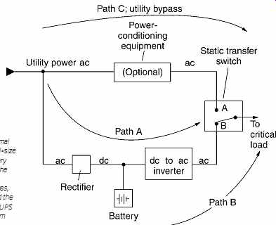
Fig. 67 In this UPS online mode, the normal power Path A is from the utility
through a full-size rectifier to the load via an inverter. The battery floats,
taking a small charging current from the rectifier. Utility failure brings
the battery line through the inverter (Path B). In both instances, the transfer
switch remains in position B and the load senses no change. Only in the event
of UPS equipment failure is power taken directly from the utility (Path C).
(c) Additional UPS Topologies
1. A money-saving arrangement called online without bypass is simply the bottom portion of Fig. 67. The first cost is reduced by elimination of the transfer switch and considerable cabling. Because failure of any of the components disables the system completely, as there is no backup power path, this system is not recommended for critical loads.
2. A system variously known as line-interactive, standby line-interactive, and hybrid interactive is shown in Fig. 68. In its normal mode (Path A), power flows from the utility lines through power conditioning equipment and position A of the transfer switch to the load. (This is identical to the normal mode of the standby system shown in Fig. 66.) In addition, however, utility ac is tapped at the power-conditioning equipment to feed the inverter that, operating in reverse as a rectifier (ac to dc), serves as a battery charger.
In the event of a utility power failure, power is drawn from the battery, which passing through the inverter, is converted to ac. It then connects to the load via the B connection in the transfer switch.
The power path is indicated on Fig. 68 as Path B. The advantage of this topology is the elimination of a large rectifier by dual use of the inverter and elimination of transients caused by switching on the inverter at full load. The system is efficient, produces little heat, and is highly reliable.
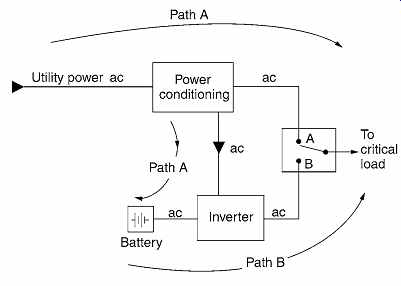
Fig. 68 In this UPS hybrid (line-interactive) mode, the normal power Path
A takes power directly from the utility but keeps the inverter on line, working
in reverse to furnish dc charging current to the battery.
Utility failure causes a change to power Path B (i.e., from battery through the inverter now operating normally to invert dc to ac). The static switch changes to position B.
TABLE 8 Typical Dimensional Data for UPS Equipment
(d) System Selection and Comparison
The preceding system descriptions are intended to provide a topical familiarity with UPS equipment arrangements. Actual selection depends upon the types and magnitudes of the critical loads, detailed outage histories, space considerations, cost factors, equipment and service redundancy, and overall system efficiency. The last characteristic can be a major decision factor where large loads are being supplied because overall system efficiencies vary from a high of about 95+% for classic standby systems (Fig. 66) to as low as 65% for some arrangements.
Because all of the power lost to inefficiency turns to heat, a low-efficiency 100-kVA/80-kW system would produce about 27 kW or about 92,000 Btu/ h! Unless this heat can be used effectively, power costs and ventilation requirements should be factored into the selection process.
(e) Ancillary Characteristics of UPS Systems
Programmable microprocessors and effective sensors and transducers have been added to basic UPS systems to produce what is known as intelligent UPS equipment. These additional devices now make readily available such operating and diagnostic data as battery status, equipment operating temperatures, load data, waveform displays, online power quality analyses, operational and event logs, and the like. These data help an informed operator optimize system functioning, anticipate problems, and keep an accurate printed operational record.
Table 8 gives some typical dimensional and run time data for UPS units of different topologies.
39. EMERGENCY/STANDBY POWER EQUIPMENT
The NEC makes a clear distinction between emergency systems and standby systems, covering the former in Article 700 and the latter in Articles 701 and 702. The equipment, circuitry, and arrangement of both are similar; the purpose is somewhat different. The reader is also referred to NFPA Standard 110, Standard for Emergency and Standby Power Systems, which covers equipment requirements for these systems.
Emergency systems are intended to supply electric power to equipment essential for human safety upon interruption of the normal power sup ply. Included in this classification are illumination in areas of assembly (to permit safe exiting and pre vent panic) and such other vital functions as fire detection and alarm systems, elevators, fire pumps, public address and communication systems, and orderly shutdown or maintenance of hazardous processes.
Standby systems are divided into two categories: those legally required (Article 701) and optional systems (Article 702). The former are intended to power processes and systems (other than those classified as emergency systems) whose stoppage might create hazards or hamper firefighting operations.
This classification goes beyond the emergency systems and could include HVAC systems, water supply equipment, and industrial processes whose interruption could cause a safety or health hazard.
It is intended primarily as a safety measure.
Optional standby systems can cover any or all loads in a facility at the discretion of the owner, and are normally intended to protect property and prevent financial loss in the event of a normal ser vice interruption. Examples might include a critical industrial process or equipment for an ongoing research project.
Health-care facilities are covered by a separate set of regulations: NEC Article 517 and NFPA Standard 99, both of which are referenced as legally binding in the vast majority of jurisdictional codes.
It is important to note that for both emergency and legally required standby systems, the provision of the system must be mandated by the authority having jurisdiction over construction, whether it is a local, state, or federal agency or a combination of these. The NEC dictates how the system is to be designed and constructed; its existence depends upon another authority.
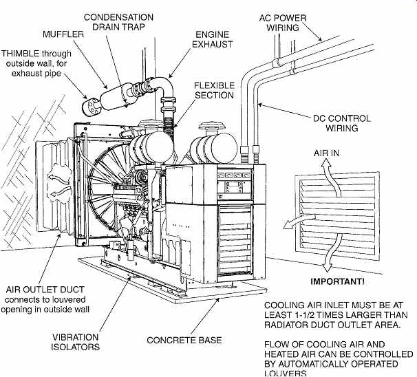
Fig. 69 Typical installation diagram of a radiator-cooled diesel engine-generator
set. The set should be oriented so that the hot radiator cooling air vented
through an outside wall flows in the same direction as prevailing winds. A
solid masonry wind and noise barrier not less than 6 ft (1.8 m) from the radiator
air outlet is recommended, as well as an elevated exhaust pipe outlet. (Illustration
courtesy of Onan Corp.)
A case in point is the fundamental issue of exit lighting. This is mandated by the NFPA Life Safety Code and Subpart E of OSHA regulations. It is not required by the NEC, and reference to NEC will not ensure its provision. The code(s) having authority and jurisdiction must specifically require an emergency and/or standby system-by that nomenclature-in order for NEC provisions to apply.
The precise items of equipment to be powered are selected by the designer, keeping in mind the specific and general requirements of the codes having jurisdiction. The majority of codes make the provisions of the NEC and the relevant NFPA standards legally binding. Most codes require emergency systems; far fewer require standby systems, and then only for essential water and water-treatment systems and a few other essential uses. The designer must thoroughly investigate the matter of jurisdictional codes before considering emergency electric power systems and equipment.
System design arrangements are discussed in Sections 28.3 and 28.6. Emergency lighting equipment and system design is covered in Section 16.31.
System equipment, which falls into two principal categories--that is, generator and battery installations--is discussed later. Optional standby systems normally use a fueled prime mover rather than batteries.
(a) Engine-Generator Sets
An engine-generator set installation comprises basically three components: a fuel system (including storage, if necessary); the set itself, plus exhaust facilities; and the space housing the equipment (Fig. 69). The principal advantages of an engine-generator set are unlimited kVA capacity, duration of power limited only by the size of the fuel tank, use for peak-load shaving, and, if properly maintained, indefinite life. The disadvantages are noise, vibration, the nuisance of exhaust piping and exhaust, the need for constant maintenance and regular testing, and difficulties with fuel storage. Gasoline can be stored for only a year at most, and subsequent disposal is difficult. Diesel fuel keeps somewhat longer, but disposal is also difficult. Use of natural gas for an engine obviates the fuel storage problem but poses the alternate problem of availability of gas ser vice during emergencies. In some large cities, steam is commercially available as an energy source. Here too, service reliability, particularly in the event of a widespread electric service failure, must be care fully investigated.
(b) Battery Equipment
Storage batteries are often used to supply limited amounts of emergency power for lighting (see Section 16.31) and for UPS systems, as detailed previously. Batteries are mounted in individual cabinets or in racks for large installations and are always provided with automatic charging equipment.
Battery types are undergoing intensive development. At this writing, the types principally in use are lead-acid, nickel-cadmium, lead-antimony, lead calcium cells, and several alkaline types. The choice depends upon the application. Installation requirements such as ventilation, gas detection, isolation, and the like depend entirely upon the type of battery, size of the installation, and battery voltage. Thus, no general guidelines for battery equipment can be given except to follow NEC Article 480 requirements and consult a battery specialist for other data.
Batteries have the distinct advantage that they can be installed either in a central system with distribution of the battery power throughout the facility or in small package units around a building. Central systems are 24 to 125 V, dc or ac, and normally feed emergency lighting only. Individual packs are used often to supply ac power via built-in inverters.
The great disadvantage of battery systems is their limited duration of power and their environmental effects upon disposal. The NEC requires that batteries maintain loads for a 1½-hour minimum, but larger capacity is frequently installed.
40. SYSTEM INSPECTION
Each electric wiring system is inspected at least twice by the local inspection authorities: once after raceways (roughing) have been installed and before the wiring and closing-in of walls, and once after the entire job is complete. The purpose of these inspections is to determine whether the design, material, and installation techniques meet the national and local code requirements. Quality of installation is the responsibility of the contractor. The designer, how ever, must be familiar with installation work and the equipment's physical characteristics in order to properly design an electrical system that will not present the contractor with unwarranted difficulties. The designer must understand and be aware of equipment substitutions by a contractor, who, having submitted a bid on the basis of plans and specifications, should be required to supply the specified equipment. Commissioning of electrical systems to the Owner's Project Requirements is recommended.