AMAZON multi-meters discounts AMAZON oscilloscope discounts
(cont. from part 2)
19. SWITCHBOARDS AND SWITCHGEAR
A switchboard is a large, free-standing assembly of switches and fuses (and/or circuit breakers), which normally provides switching and overcurrent protection to a number of circuits connected to a single electric source. Metering and other instrumentation are also often included. A switchboard may be represented in a single-line diagram, as shown in Fig. 23. This equipment serves to distribute, with adequate protection, bulk power into smaller "packages." Thus, in a hydraulic analogy, the main buswork of the switchboard is equivalent to a main water supply header, the switches to on/off valves, the fuses to flow-limiting devices, and the feeders to sub-piping connected to the main header.
Modern switchboards (Figs. 24 to 27) are all dead-front; that is, they have all circuit breakers, switches, fuses, and live parts completely enclosed in a metal structure. The operator controls all devices by means of pushbuttons and insulated handles on the front panel. Circuit breakers equipped with bayonet-type contacts, each mounted in a movable drawer (like the drawers of a standard letter file) in a switchboard, are described as the drawout type. This drawout arrangement facilitates emergency replacements, inspection, and repairs and is illustrated in Fig. 26.
No clear distinction is made between the terms switchboard and switchgear, although the terms suggest a sense of scale. Generally, low voltage switchboards with large circuit breakers and all high-voltage equipment (above 600 V) are referred to as switchgear. When molded-case circuit breakers are utilized in a switchboard, it is often referred to as a building-type switchboard.
Recommended minimum space requirements for various types of switchgear are shown in Fig. 28. Working space around all types of electrical equipment must meet the requirements of NEC Article 110. Main metal-clad switchgear for commercial, industrial, and public buildings is almost invariably located in a basement and housed in a separate well-ventilated electrical switchgear room. Smaller sub-distribution switchboards require no special room. A wire screen enclosure to prevent tampering or vandalism plus a large "DANGER- HIGH VOLTAGE" sign are usually adequate. The architect must provide adequate exits, hallways, and/or hatches for the installation and removal of all equipment. Specifications for switchgear should state the maximum overall dimensions of sections that will be transported and installed in one piece.
When switchgear is to be installed outdoors, one of three methods is employed: build a small structure to enclose normal indoor gear, utilize weatherproof outdoor gear, or utilize switchgear that is built into its own exterior enclosing structure, as seen in Fig. 27. These housings are equipped with heating and lighting and often prove to be the most economical choice.
Fig. 24 Free-standing, indoor-service, low-voltage (600-V) switchboard with
group-mounted, fixed molded-case circuit breakers.
The deeper section contains the service entrance main circuit breaker (maximum 3000 A) plus instrumentation. Section width varies from 30 to 45 in. (0.75 to 1.1 m) and depth from 18 to 36 in. (0.5 to 0.9 m), depending upon the main circuit breaker rating. The smaller section contains branch circuit breakers. All units are 90 in. (2.3 m) high. (Photo courtesy of Cutler-Hammer.)
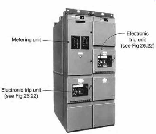
Fig. 25 Metal-enclosed, indoor, low-voltage power switchboard with fixed or
drawout large circuit breakers. Maximum bus capacity is 5000 A. Section dimensions
vary with the size and type of contained equipment. All units are 90 in. (2.3
m) high. Each circuit breaker is equipped with a microprocessor-controlled
trip unit. It can be seen clearly on the front of each unit. In addition, another
programmable solid-state metering/analysis unit can be seen at the left of
the top compartment of the entry (left) cubicle of both this switchgear and
the switchboard. (Photo courtesy of Cutler-Hammer.)
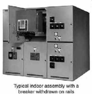
Fig. 26 Three sections of medium-voltage metal-clad draw out switchgear, suitable
for indoor use as shown and for outdoor use with cabinet modification. Voltage
ratings are 5-27 kV; current ratings are 1200-3000 A. Each indoor section measures
36 in. W × 95 in. H × 96 in. D (0.9 × 2.4 × 2.4 m) and contains two compartments
for circuit breakers and/or instrumentation. Due to the drawout characteristic
(shown), a 72-in. (1.8-m) front aisle is required. Similar outdoor aisle-less
switchgear measures 36 in. W × 115 in. H × 101 in. D (0.9 × 2.9 × 2.6 m). (Photo
courtesy of Cutler-Hammer.)
20. UNIT SUBSTATIONS (TRANSFORMER LOAD CENTERS)
An assembly, comprising a primary voltage switch and-fuse or circuit breaker, a step-down trans former, meters, controls, buswork, and secondary (low-voltage) switchgear, is known as a unit sub station or a load-center substation. Its function is to accept an incoming high-voltage power supply, transform the high voltage to a voltage that can be utilized in the facility, and distribute the low-voltage power through associated low-voltage (secondary) switchgear. A dimensional physical sketch of a typical unit substation, along with its electrical single line diagram, is shown in Fig. 29. Equipment is available for indoor or outdoor installation.
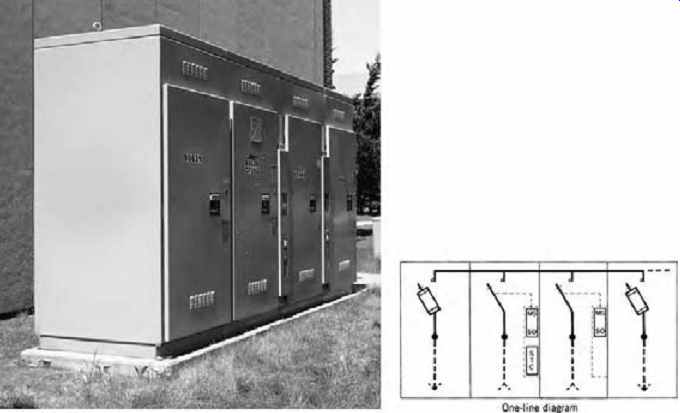
Fig. 27 Four-bay (section), power-operated, high-voltage service entrance
switchgear rated 13.8 kV, consisting of (see the single line diagram inset,
and reading from left to right) a fused feeder section, two bays with parallel
incoming lines and automatic transfer in the event of power failure, and a
second switch and fuse feeder section. Fuses are electronic, with circuitry
designed to provide a trip signal when excessive current is sensed, rather
than simply relying on the thermal characteristic of a fusible element. This
gear, which measures 93 in. H × 172 in. W × 44 in. D (2.4 × 4.4 × 1.1 m) and
weighs 8000 lb (3630 kg), is suitable for interior or exterior installation.
(Courtesy of S&C Electric Co.)
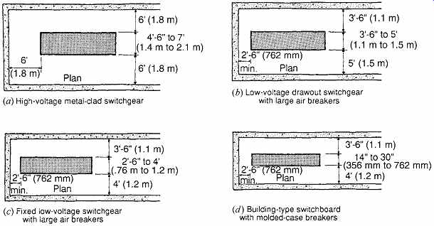
Fig. 28 Typical nominal switchgear space requirements. Each room should have
two doors when switchgear is connected to high capacity systems or operates
at high voltage. Switchgear is shown in plan view. For detailed space requirements,
see NEC Article 110.
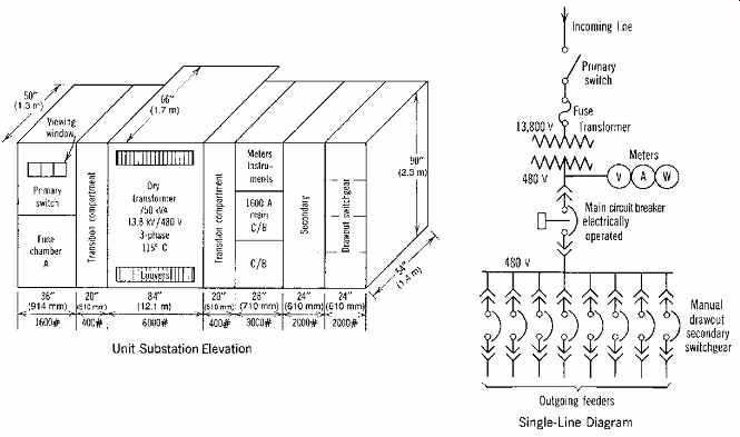
Fig. 29 Approximate sizes and weights of a typical large single-ended unit
substation. Such a unit would supply a building with a maximum demand of 750
kVA. The incoming 13,800-V cables enter cubicle A and connect to the primary
switch and fuses. The load side of the fuses connects to the transformer, which
in turn connects to the secondary switchgear. The main secondary switchgear
then feeds various switchboards and panelboards distributed throughout the
building.
If installed indoors, the location of a unit substation is governed by the type of transformer utilized, as explained in the discussion on indoor transformer installations. For this reason, almost all indoor unit substations utilize dry-type (air filled) transformers. A basement location is most often selected, with ventilation requirements as detailed previously. Access should be restricted to authorized persons. Unit substations are selected to obtain the economies inherent in prefabricated construction using coordinated components.
21. PANELBOARDS
An electrical panel, or panelboard, serves essentially the same function as a switchboard except on a smaller scale. It accepts a relatively large block of power at some downstream point in a system and distributes it in smaller blocks. Like a switchboard, it comprises main buses to which are connected circuit-protective devices (breakers or fuses) that feed smaller circuits. The panelboard level of a system usually represents the final distribution point, thence feeding out to the branch circuits that contain the electrical utilization apparatus and devices, such as lighting, motors, and so on. Small panels, particularly in residential work, are frequently referred to as load centers.
The panelboard components-the buses, breakers, and so on-are mounted inside an open metal cabinet called a backbox. The backbox is pre fabricated with knockouts at the top, bottom, and
sides to permit connection of conduits carrying circuit conductors (Fig. 30). The main feeders that supply power to the panel's busbars enter through the large knockouts in the metal backbox, as in Fig. 30. Details of panelboard construction are presented in Fig. 31. A panel may be equipped with a main circuit breaker whose function is to disconnect the entire panel in the event of a major fault.
Figures 30 and 31 show panelboards with only branch circuit devices and no main breaker or switch. These panels are described as "lugs in mains only," which means that the panel has only connectors (lugs) on the main busbars for connection of the main feeder cables and no main protective device. The backbox is closed with a protective front panel with an access door. Three basic panelboard types are shown in Fig. 32.
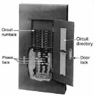
Fig. 31 Cutaway of a typical lighting and appliance panel board. Branch circuit-protective
devices are normally arranged in two vertical rows even in 3-phase panels.
The circuit directory on the inside of the panelboard door gives a brief description
of the loads connected to each branch circuit breaker.
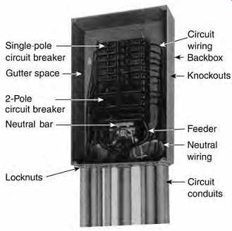
Fig. 30 A wired panelboard is shown with the cover removed. This panel is
single-phase, 3-wire, meaning that it has two phase bars and a neutral (note
the three heavy feeder cables). Lighting and appliance panels such as this
are 4½-6 in. (115-150 mm) deep, 16-20 in. (400-500 mm) wide, and of sufficient
height to accommodate the devices. The top device may be no higher than 78
in. (2 m) above the finished floor (AFF) and the bottom one no lower than 18
in. (450 mm) AFF to meet NEC requirements.
The line terminal of each circuit-protective device (breaker or fused switch) is connected to the busbars of the panelboard. The load terminal of the device then feeds the outgoing branch circuit. This is shown schematically in Fig. 33, which is a line drawing representation of an electrical panelboard.
Notice that the circuit breakers are arranged in two vertical rows, corresponding to actual construction practice. In the illustrated line drawing, a 3-phase panel is shown (i.e., three-phase busbars and a neutral bar). The busbars of the panelboard are energized by a feeder from a switchboard or large power distribution panel.
Panelboards are described and specified by type, bus arrangement, branch breakers, main breaker, voltage, and mounting-although not necessarily in that order. A typical description might be: lighting and appliance panel, 3-phase, 4-wire; 200A mains; main c/b, 225A frame, 150A trip. Branch breakers-all 100A frame; 8 ea. SP-20A, 4 ea. 2P 20A, 4 ea. 3P-20A; flush with hinged locked door.
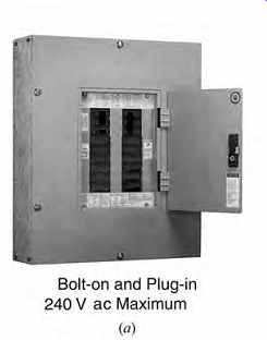
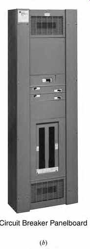
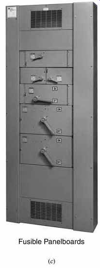
Fig. 32 Three different designs of panelboards. (a) Circuit breaker-type panelboard
using bolt-on and plug-in molded-case circuit breakers 1- to 3-pole, 15-100
A. A main device of up to 400 A can be installed. The panel is rated for 240V
ac. The illustrated panel, which is arranged for surface mounting, measures
30 in. H × 20 in. W × 5¾ in. D (760 × 510 × 145 mm). (b) Circuit breaker distribution
type panelboard with maximum bus ratings of 1200 A and 600 V ac. Branch circuit
breakers can be 15-100 A, single-pole and 15-1200 A, 2- or 3-pole. These panels
are free-standing but can be wall-mounted, provided that the highest device
does not exceed 6 ft, 6 in. (2 m) AFF. Similar units are available with a front
door. Depending upon the contents, cabinets can be 24-36 in. (610-915 mm) W
× 60-90 in. (1.5-2.3 m) H × 6-8 in. (150-200 mm) D. (c) Switch- and fuse-type
distribution panelboard, free-standing, with ratings similar to those of the
circuit breaker type in (b). Cabinets are 36-44 in. (915-1115 mm) W, 74-90
in. (1.8-2.3 m) H, and 10½ in. (265 mm) D. (Photos courtesy of Cutler-Hammer.)
22. PRINCIPLES OF ELECTRIC LOAD CONTROL
The key to energy conservation and electric demand limitation is load control. In the recent past, the extent to which both of these desirable operating functions were put into practice was essentially an economic decision: Would the electric billing savings justify the expense of installing the required control? Today, and increasingly in the future, legislation resulting from environmental pressures will mandate energy-consumption limitations. Already many states have enacted legislation requiring lighting controls in certain nonresidential buildings, and the trend toward additional and more stringent future requirements is clear. The rationale for load control to limit demand charges was discussed previously.
Lighting control strategies are discussed in Section 15. The essential control principle that applies to all loads, not only to lighting, is straight forward: The load is switched or modulated in response to a control signal (Fig. 34a). In terms of hardware, the process is somewhat more complex. Figure 34b shows in principle the equipment and wiring required in a common application: time control of exterior lighting, with photocell override. Figure 35 shows a more complex arrangement for area lighting control with local override, as might be installed in conjunction with a commercial office building. In each case, there are signal-initiation devices, one or more relays that perform the actual electrical switching, and control and power wiring-in addition to the main power wiring from the panelboard.
Many past users found that the payback from reduced electric billing was insufficient to cover the control equipment cost, particularly where local and/or remote override was required, and as a result relied on inefficient and generally ineffective manual control. That option, however, is limited today and will become even more so in the future.
As a result, a more economical way to accomplish the required control functions was developed, thanks in large measure to modern miniaturized programmable control elements. These can be installed directly in the lighting panelboard. Such a panel is known in the industry by the generic term intelligent panelboard and by various trade names that identify specific manufacturers.
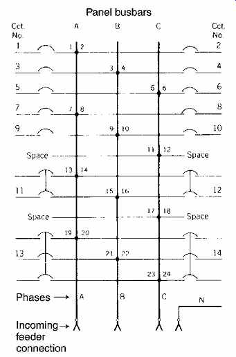
Fig. 33 Typical schematic diagram for a panel. Note that single-pole, 2-pole,
and 3-pole circuit breakers are connected to 1-, 2-, and 3-phase buses, respectively.
They supply 120-V 2-wire, 120/208-V 3-wire, and 120/208-V 3-phase 4-wire, respectively.
This panelboard would be described as a 3-phase 4-wire lighting and appliance panel, with 10 SP, 2-2P, and 2-3P circuit breakers, lugs in mains only. The voltage of the panel and the ampere ratings of buses and all circuit breakers would then be specified.
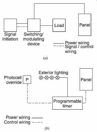
Fig. 34 (a) A low-voltage lighting control system always includes the elements
shown. Signal initiation can come from a sensor such as a photocell or from
a control device such as a timer, an override signal, a central computer signal,
and the like.
The signal activates the power-switching device, which in turn switches or modulates the load. The power source is always the associated lighting panelboard. (b) Schematic arrangement of a control system for exterior lighting. If the system is compact, a switching timer would be used. For a spread system, timer controlled switching relays at each fixture would be used with attendant additional control wiring. Grouping of the fixtures into different control sequences (road, parking lot, building entrance, etc.) further complicates the wiring.
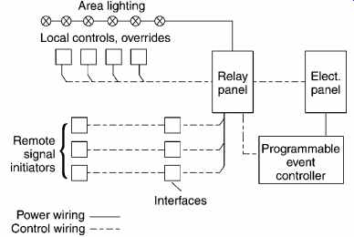
Fig. 35 Schematic diagram showing equipment and connections that might be
used for control of a block of lighting in a large commercial building. The
wiring can be even more complex and extensive if control of smaller lighting
groups is desired or if control is desired from more than one location.
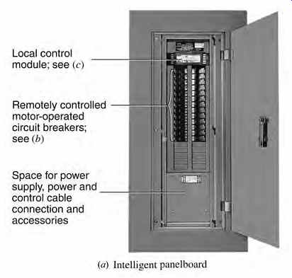
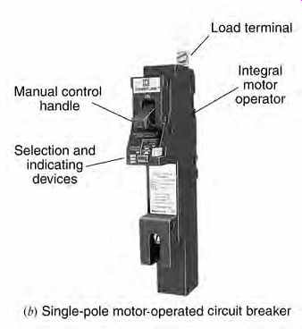
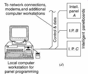
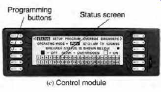
Fig. 36 (a) This intelligent panelboard contains (from top to bottom) a microprocessor
control module, 26 single-pole, remote-controllable (motor-operated) circuit
breakers, space for 10 additional poles, and a compartment containing a dc
power supply (for circuit breaker operation) and accessories.
(b) This motorized single-pole circuit breaker can be manually or remotely controlled. Electric operation latches the circuit breaker so that in the event of power failure, all breakers remain in their pre-outage condition. The illustrated unit is a 100-A frame, 20-A trip unit. A status window on each unit displays its condition, while electronic sensors in each unit sense voltages and indicate on the control panel the status of each unit. (c) The control module, mounted at the top of the panelboard, is equipped with programming buttons that allow control of each circuit breaker individually. The illustrated basic control module programs and controls essential functions, including configuration, circuit breaker status, resetting, zoning, settings for hardware characteristics, over ride modes, screen selection, and self-diagnostics. Additional control modules (not shown) supply time-based programming, logging functions, and timed functions. The illustrated breaker status screen is one of five displays. The others are setup, program, override, and diagnostic screens. (d) Intelligent panels can be incorporated into a large control network by use of interface connections of various types (not shown). The illustration is a block diagram showing one of the net working possibilities. (All photos courtesy of Square D.)
23. INTELLIGENT PANELBOARDS
The idea behind an intelligent panelboard is straightforward. If many of the necessary electric load control and switching functions are incorporated into the panelboard by use of a com pact, centralized, programmable microprocessor, the corresponding external devices and associated wiring are eliminated. The switching function is made possible by the use of motor- or solenoid operated panel circuit breakers, thus taking advantage of their switching capability and eliminating the need for relays, contactors, and switches. The internal central controller permits local programmable control of each panel circuit breaker individually.
This central panel-mounted controller can also accept signal data from individual remote or network sources and can provide status reports, alarm signals, operational logs, and local bypass and override functions. Control cards in an adjacent cabinet, connected to the controller, can pro vide local switch override, daylight dimming and on-off control, telephone override energy control, electric demand control, and networking. With careful planning, the high initial cost of an intelligent panelboard can be offset by elimination of remote relays, relay panels, programmable time switches, remote-control switches, and all of their associated wiring. Simplified and improved facility operation, plus reduced maintenance costs and electric bills, are additional benefits that can be achieved with proper application and careful design. Figure 36 shows the essential elements of an intelligent panelboard and a typical network arrangement using the remote-control capabilities of such panels.
24. ELECTRIC MOTORS
Motors are frequently supplied along with the equipment they drive (such as fans, blowers, and so on) as part of a complete package. The actual choice of motor is left to the driven-equipment supplier, because the supplier is presumed best qualified to select a motor that will optimally match the driven-equipment requirements for whose proper operation the supplier is responsible. In practice, however, a supplier is frequently guided primarily by price-low first cost being a recurring theme in building design and construction, very often to the detriment of low life-cycle cost. The designer, therefore, should be sufficiently knowledgeable so that the best motor for the application can be specified. The following sections are written with that purpose in mind, and are primarily concerned with application.
(a) Direct-Current Motors
These motors are not normally used in building work. The fine speed control (for which they were primarily used) is now available, more economically, with ac motors, as explained in Section 26.
(b) Alternating-Current Motors
These motors fall into three general classifications: poly-phase induction motors, poly-phase synchronous motors, and single-phase motors.
Within these categories there are further subdivisions. Of these many types, most motors used in building equipment are squirrel-cage induction machines; therefore, this type is studied in some detail.
(c) Squirrel-Cage Induction Motors
This type of induction motor owes its interesting name to an early design in which the rotor consisted of a group of bars welded together into a cylindrical cage-type shape. The design, invented by Nikola Tesla, is basically unchanged today except for refinements. Squirrel-cage motors are manufactured in four different NEMA designs to meet different application requirements. Of these the most common are:
Type B: standard design, high efficiency and power factor, normal torque; applicable to fans, blowers, and pumps Type C: high starting torque, fair efficiency and power factor; applicable to compressors, conveyors, and other devices that start under load A motor nameplate gives important information on a motor that is not self-evident:
1. Type: This is the manufacturer's designation and indicates primarily the enclosure. Common enclosures are open drip-proof, totally enclosed, fan-cooled, and weather-protected.
2. Duty (time rating): Continuous or intermittent.
3. Service factor: Permissible overload; generally 15%.
4. kVA code: Indicates by a letter the maximum starting current per horsepower. This is useful in selecting motor-protective devices. More recently, actual locked rotor amperes have been given.
5. Frame: A NEMA standard number that indicates the motor's physical dimensions.
6. Motor voltage: The standard motor voltages are 208, 230/460, and 575 V. Induction motors generally operate satisfactorily at +/- 10% voltage. Only 208-V motors should be used on 208-V systems because the actual line voltage may be as low as 200 V. Using a 230-V motor on a 200-V circuit will result in sharply reduced torque, increased temperature rise, and poor overload capacity.
7. Motor nominal full-load efficiency: As stated; a requirement of ANSI/ASHRAE/IESNA Standard 90.1 and EPACT.
8. Design letter: Indicates inherent motor design characteristics.
(d) Electric Motor Energy Considerations The federal Energy Policy Act of 1992 (EPACT; subsequently updated/amended in 2005) required that the most common designs of induction motors, accounting for 70% to 80% of all poly-phase induction motors sold in the United States, meet higher efficiency and power-factor standards. Specifically, these efficiency standards apply to single-speed, poly-phase, squirrel-cage induction motors, designs A and B, continuous rating, and operating at 230/460 V, 60 Hz. These motors are known as premium efficiency or PE motors.
The decision on whether to use a PE motor in applications not mandated by law is essentially an economic and environmental one. Many motor manufacturers make available straightforward software that enables a designer to rapidly make a detailed life-cycle cost comparison among motor types, with operating time, loading, first cost, energy and maintenance costs, and so on as the variables.
As a guideline, motor applications involving low starting torque and frequent motor operation at partial load are likely candidates for short payback periods on the price premium of PE motors. Higher efficiency also results in reduced consumption of the typically nonrenewable energy resources used to generate electricity.
25. MOTOR CONTROL STANDARDS
Until recently, American designers and equipment manufacturers utilized motor control equipment manufactured to NEMA standards exclusively.
It was also common practice in the construction industry to split the motor and motor-control pack age by having equipment manufacturers supply the motorized equipment while the electrical construction contractor supplied the motor control equipment. Few coordination problems between controller and motor drive were encountered because control equipment sized and built to NEMA standards is large, heavy duty, and applicable to a wide range of motor sizes and characteristics.
The International Electrotechnical Commission (IEC) is a technical organization with 52 full (including the U.S.) and 17 associate member nations. It develops recommended standards for electrical equipment, including motor controls.
The IEC design concept is one of close coordination between a motor and its controller. This application sensitivity, coupled with flexible ratings for a single piece of equipment, depending upon its application, makes equipment built to IEC standards smaller, lighter, and cheaper than similarly rated equipment built to NEMA standards. As a result, many U.S. manufacturers utilize IEC motor controls in conjunction with their motive equipment, particularly on international jobs. Because American architects, engineers, and contractors are involved in a large number of construction projects outside of the territorial United States, those responsible for designing, specifying, and purchasing electrical equipment in general, and motor control equipment in particular, should be aware of the comparative characteristics of NEMA-based and IEC-based equipment.
26. MOTOR CONTROL
(a) Fundamentals
A conventional ac motor controller is basically a contactor (see Section 14) designed to handle the heavy inrush currents involved in starting an ac motor. Its function is twofold: to start and stop the motor and to protect it from overload. These two separate and distinct functions are accomplished by combining a set of contacts for on/off control with a set of thermal overload elements for overload protection in a single unit. When the contacts are operated by hand, the controller is called a manual starter; when the contacts are operated by a magnetic coil controlled by pushbuttons, thermostats, or other devices, the unit is known as a magnetic controller or, simply and more commonly, a magnetic starter.
Motors of 1 hp (0.75 kW) or less are generally controlled by a manual switch that contains an overload protection device. It is advisable to utilize such a device for all fractional horsepower (low kW) motors.
Most starters are of the full-voltage across the-line (ATL) type; that is, the contacts place the motor directly onto the line, and the motor starts up immediately. When such a procedure is undesirable because of voltage dip and flicker caused by the large inrush current or because of utility company limitations, a reduced-voltage starter, sometimes called a compensator, is used. These units initially apply reduced voltage to the motor, thus reducing the starting inrush current and line voltage drop.
This in turn reduces dimming of lights, flicker, and other undesirable effects.
Older reduced-voltage starters use a stepping arrangement whereby voltage is increased incrementally, thus limiting inrush current. Unfortunately, starting torque is also limited, thus restricting the application of these starters. Solid state starters that have been available since the late 1980s provide continuous (stepless), controlled motor starting. These units not only limit inrush current, but also, by adjusting the acceleration time, allow the required starting torque of the motor to be maintained. Such starters provide soft starts (i.e., starts that minimize the mechanical stresses caused by rapid application of accelerating torque). Additional advantages of these units are reduced size and weight, long life, more sophisticated motor protection, and additional operating functions such as jogging and reversal. Disadvantages are higher cost and possible radio frequency noise problems (Fig. 37).
(b) Motor Speed Control
Many applications in HVAC, fluid piping, and industrial systems require speed control of electric motors. Until recently, this constituted a problem whose solution was expensive, often space consuming, and rarely energy-efficient. The reason for this is that the common squirrel-cage induction motor is essentially a constant-speed device, where speed is determined by power line frequency and motor design. Speed drops slightly (slips) as the load increases. Until the advent of cheap electronic power equipment, speed control was usually accomplished by using a wound-rotor motor in lieu of a squirrel-cage unit. This drastically increased both motor and controller costs while providing only limited speed control.
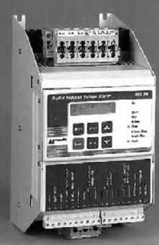
Fig. 37 Soft starter type for 3-phase induction motors of up to 1400 hp (1045
kW), shown without an enclosure. This microprocessor-based unit provides two
selectable starting characteristics with stepless acceleration, plus additional
control and protection functions including reversing control, over- and undervoltage
and current protection, and two normal motor operating speeds.
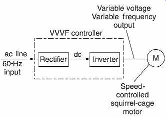
Fig. 38 Schematic representation of the action of a variable voltage, variable-frequency
(VVVF) motor speed controller. Line voltage at 60 Hz is rectified to dc and
the inverted voltage to ac. Frequency and voltage control are built into the
inverters, designed to maintain a constant voltage-to-frequency ratio. This
constancy is necessary to prevent malfunction of the motor as its speed is
varied.
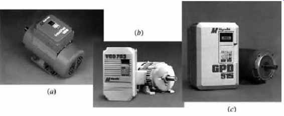
Fig. 39 Three modern programmable, microprocessor-controlled motor controllers.
(a) Integrated motor and controller for motors of up to 1 hp (0.75 kW). The
controller provides a soft start, a speed control range of 40:1, high efficiency,
multiple speed settings, and full motor protection. (b) Controller for motors
of up to 3-phase, 400 hp (300 kW); this type of unit provides programmable
functions including speed control from standstill to double-rated speed, reversing,
adjustable acceleration, and full motor protection. (c) Controller that can
be programmed for three different control modes. Speed control range, regulation,
and torque curves vary in each mode to suit the specific controlled load. The
controller has low harmonic distortion plus fault diagnostic software, in addition
to the normal overload and protective characteristics. It also has terminals
for remote monitoring and control plus network control capabilities. A 20-hp
(15-kW), 230-V controller in a NEMA 1 (indoor) enclosure measures approximately
16 in. × 10 in. × 9 in. (400 × 250 × 230 mm) and weighs 24 lb (11 kg). (Photos
courtesy of Magnetek.)
Advances in power electronics have made practical a variable-voltage, variable-frequency (VVVF) controller that gives smooth, continuous speed control over a range exceeding 30 to 1 while maintaining motor torque. These highly reliable controllers, also known as variable frequency drives (VFD), provide considerable energy economies that usually result in rapid payback of the relatively high first cost of equipment. The essentials of the VVVF control scheme are shown in Fig. 38. Voltage control, in addition to frequency control, is necessary in order to maintain a constant voltage/frequency ratio, which is necessary for efficient, safe operation. An increase in this ratio results in over heating of the motor, whereas a decrease results in insufficient torque. Additional advances in power electronics have produced motor speed controllers with controlled speed ratios approaching 1000:1.
One disadvantage of these speed controllers has been the production of line harmonics and radio noise of sufficient strength to constitute a serious engineering problem. At this writing, these problems have been mitigated, and will undoubtedly be pursued to the point that, except for highly sensitive areas, the interference will be negligible. At this point, however, the designer must investigate these effects for the particular application. Typical adjust able-frequency controllers are shown in Fig. 39.
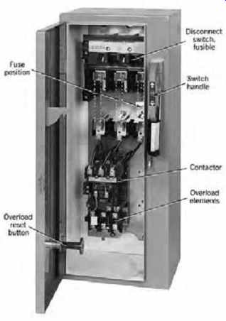
Fig. 40 Interior of a conventional (non-solid-state) combination fused switch-type,
across-the-line motor controller. Note that the unit is essentially a switch
and a starter wired together and installed in a single cabinet. Approximate
dimensions of the illustrated unit are 20 in. W × 48 in. H × 9 in. D (510 ×
1140 × 230 mm), with a 75-hp (56-kW) capacity. (Courtesy of Allen Bradley Co.)
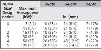
TABLE 6 Rating and Approximate Dimensions of ac Full-Voltage Conventional
Single-Speed Motor Controllers, 3-Phase Combination Circuit Breaker Type b
27. MOTOR CONTROL EQUIPMENT
All the starters discussed previously are available in a wide range of sizes, voltages, and enclosure types. Every motor controller is required by the NEC to have a disconnecting means for safety reasons.
Where convenient, this disconnect switch may be combined with the starter into a single unit known as a combination starter. A circuit breaker or fused switch is often used in such an arrangement, which then constitutes the branch circuit protection and disconnecting means (Fig. 40).
A typical, brief description of a conventional motor controller would be similar to the following: combination circuit-breaker type, across-the-line motor controller, NEMA size 2, three O.L. (overload) elements, 208 V, in a NEMA 1 enclosure. Starter shall contain integral on/off pushbuttons.
Table 6 gives the approximate dimensions of one particular type of combination starter.
As with other electrical equipment, a current manufacturer's catalog must be consulted for reliable data on a particular manufacturer's products.
Dimensions vary somewhat among manufacturers (while still meeting NEMA specifications). As noted previously, physical characteristics for control equipment of similar ratings can vary greatly among items made to meet IEC specifications and those made to NEMA specifications.
Where several motors are installed in close proximity to one another, it is often convenient from the control perspective, as well as economically, to combine the motor starters, disconnect switches, motor controls, and indicating devices into a single large assembly. Such an assembly is called a motor control center (MCC). Typical MCC types are shown in Fig. 41.
28. WIRING DEVICES: GENERAL DESCRIPTION
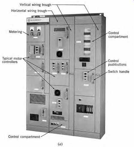
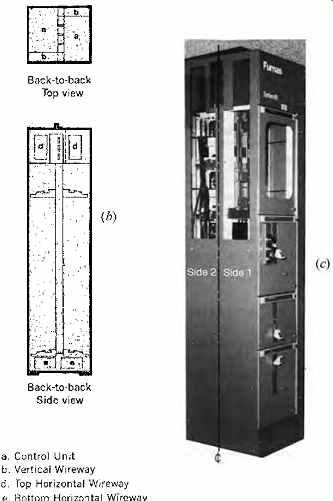
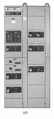
Fig. 41 Motor control centers (MCC) of various constructions. (a) Conventional
MCC construction with magnetic motor starters, manual local control, analog
metering, and conventional overload and protective equipment. (b) Back-to-back
construction of conventional MCC adds only 5 in. (125 mm) to the basic 15-in.
(380-mm) depth. (c) Units are 90 in. (2.3 m) high and 20 in. (500 mm) wide
per section. Solid-state controllers can be installed in this unit, as well as
in the MCC shown in (a), along with conventional magnetic contactors. (d) MCC
that uses solid state programmable controllers with heaterless overload protection.
The unit also provides protection against phase loss, single phasing, and ground
faults. Single side units in this construction are 90 in. (2.3 m) H × 20 in.
(500 mm) W × 16-20 in. (400-500 mm) D (depending upon starter size). Back-to-back
construction is 21 in. (534 mm) D. (Photos courtesy of Allen-Bradley [a], Siemens
Furnas [b, c], and Cutler-Hammer [d].)The general term wiring devices includes
all devices that are normally installed in wall outlet boxes, including receptacles,
switches, dimmers, fan controls, and so on. Attachment plugs, also called caps,
and wall plates are also included in wiring devices.
There are three grades of device quality, using NEMA and UL grading nomenclature: hospital grade, federal specification grade, and UL general purpose grade-in descending order of price and quality. Inasmuch as these grades correspond to published specification requirements, they are the only reliable gauge of construction quality. Hospital-grade devices are identified by a green dot on the device face. These devices are built to withstand severe abuse while maintaining reliable operation and must meet UL requirements for this grade.
Manufacturers usually grade their devices as hospital grade, premium or industrial specification grade, commercial specification grade, and residential grade, in descending order of quality and price.
Hospital grade is approximately the same among manufacturers because industry standards must be met. Industrial and commercial specification grades correspond roughly to federal specification grade, and residential grade to UL general-purpose grade.
Manufacturers' grades are qualitative, although reputable makers list the NEMA and UL specifications that each of their grades meets. It is only on this standardized basis that a technical quality com parison can be made.
In application, industrial specification grade equipment is usually used in industrial and high grade commercial construction; commercial specification grade in most educational and good residential buildings; and standard or residential grade in low-cost construction of all types. The grade of wiring devices should, as with all electrical equipment, be consistent with the quality of construction in the facility as a whole.
Although historically the term wiring device referred to devices that operate at line voltage (120, 208, 240, and 277 V) in a branch circuit, the term today also includes low-voltage lighting control devices, fan controls, and the like. The accepted criteria seem to be that only devices rated 30 amps or less, that can be mounted in a small wall box, are considered wiring devices. Communication attachments are not usually considered wiring devices, even when they are supplied by the electrical contractor. They are part of premise wiring, which is the term commonly used to describe data and communication system wiring, raceways, and devices.
29. WIRING DEVICES: RECEPTACLES
A receptacle is, by NEC definition, "a contact device installed at the outlet for the connection of a single attachment plug." This usually takes the form of the common wall outlet or, as illustrated later, larger and more complex devices. A comment about terminology is required. The common wall outlet is properly called a convenience receptacle outlet, a receptacle outlet, or a convenience outlet. The term wall plug, which is heard so often, is incorrect. A plug is another name for the attachment device (cap) on the wire that carries electricity to the appliance. The device at the end of the line cord is plugged into the wall, hence plug.
Because by NEC definition a receptacle is a contact device for the connection of a single attachment plug, and because the normal wall convenience receptacle will accept two attachment plugs, it is properly called a duplex convenience receptacle or duplex convenience outlet. Most people shorten this term to duplex receptacle or duplex outlet.
Receptacles are identified by the number of poles, the number of wires, and whether the device is designed for connection of a separate equipment ground. (This ground may connect to a separate equipment-grounding wire or to the metallic conduit system, according to system design.) The number of receptacle poles equals the number of current-carrying contacts, including the neutral.
The equipment ground connection (pole) is not counted because it does not (normally) carry cur rent. The number of wires includes the equipment ground connection because it is wired. The equipment ground connection (grounding pole) should not be confused with the system ground (usually the neutral pole), nor may the wiring for the two be interchanged.
In a typical application, a receptacle for an electric dryer with a 4800-W, 208-V heating element and a 1/ 6-hp (0.12 kW), 115-V motor would be NEMA 14-50R (Fig. 42). The motor would connect across W and X, the heater across X and Y, and the appliance case to G. Receptacles installed on standard 15- or 20-A branch circuits must be of the grounding type. Receptacles connected to different voltages, frequencies, or current type (ac or dc) on the same premises must be polarized so that attachment plugs are not interchangeable. Figure 42 shows some of the standard receptacle configurations and their ratings. Figure 43 shows typical receptacle construction plus enclosures for use in damp and wet locations.
Receptacles are readily available from 10 to 400 A, 2 to 4 poles, and 125 to 600 V. In addition, special types such as locking, explosion-proof, tamperproof, and decorative design units are made.
Also, specific-usage devices, such as electric range receptacles, are available. All receptacles other than the normal 15/20-A, 3-wire, parallel-slot type should be specified to be furnished with at least two matching caps (plugs). A typical receptacle specification would be: receptacle, duplex, 2-pole, 3-wire, grounding type, 20 A, 250 V, federal specification grade, for indoor use. Receptacles are normally mounted vertically between 12 and 18 in. (305 to 457 mm) above the finished floor (AFF), except that in shops, labs, and other areas where tables are placed against the walls, 42 in. (1.07 m) is the usual mounting height.
In addition to these types, several manufacturers produce a receptacle with built-in ground-fault circuit protection (Fig. 44). For a discussion of these ground-fault circuit interrupter (GFCI) receptacles.
The great sensitivity of modern electronic equipment to voltage surges and electrical noise (random, spurious electrical voltages) has led to the development of two special receptacles. Receptacles with built-in surge suppression protect connected equipment from overvoltage spikes. Receptacles with an insulated equipment-grounding terminal separate the device ground terminal from the system (raceway) ground because it has been determined that much unwanted electrical noise can be eliminated by such disconnection. The receptacle's insulated ground terminal is connected to an isolated green ground conductor that carries through the entire system but is connected to the system ground at the service entrance only; hence the name isolated ground. Isolated ground receptacles are identified by an orange triangle on their face (see Fig. 45). A receptacle with built-in surge suppression (see Section 37) is shown in Fig. 45.
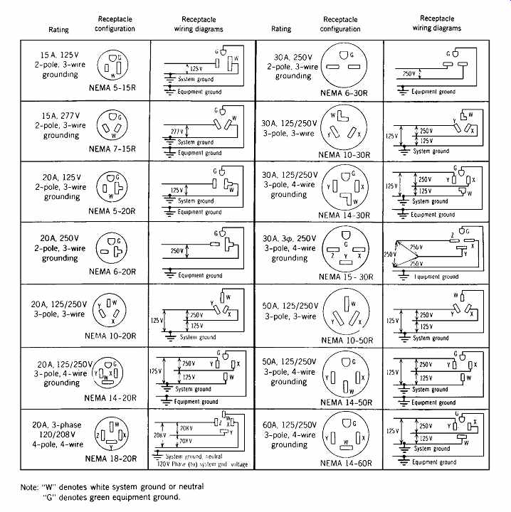
Fig. 42 Receptacle configuration chart with selected common general-purpose,
nonlocking devices with associated NEMA designations.
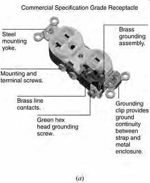
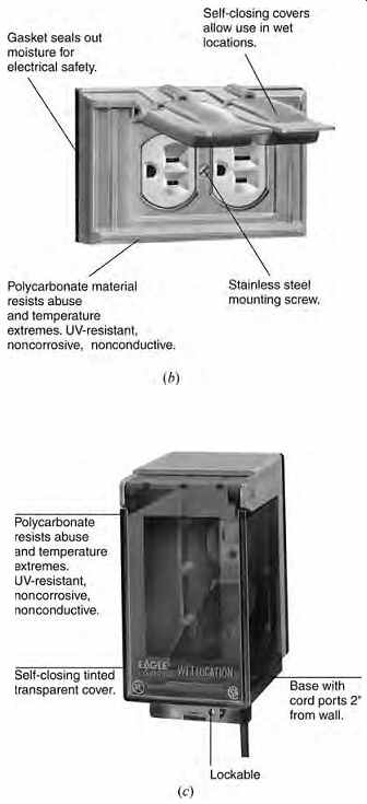
Fig. 43 (a) Cutaway of a commercial, specification-grade duplex convenience
receptacle showing its construction. (b) Receptacles installed in damp locations,
outdoors but not exposed to the rain, or in wet locations but used to energize
portable equipment and continuously attended, should have a cover that is
weatherproof when the attachment plug cap is removed, of which one type is
illustrated. (NEC Article 410-57b[2].) (c) Receptacles in wet locations (that
may be in use unattended) must have a weatherproof enclosure, the integrity
of which is not affected by the attachment of a plug. One such enclosure is
illustrated. (NEC Article 410-57b[1].) (All photos courtesy of Eagle Electric
Manufacturing Co., Inc.)
30. WIRING DEVICES: SWITCHES
Switches of up to 30 A that can be outlet-box mounted fall into this category. Generally, because of their better construction, ac-only switches are preferable to the ac/dc type. The usual ac switch rating is 15, 20, or 30 A at 120 or 120/277 V. Usual constructions are single-pole, 2-pole, 3-way, 4-way, momentary-contact, 2-circuit, and maintained-contact SPDT (single-pole, double-throw) and DPDT (double-pole, double-throw). Operating handles are toggle, key, push, touch, rocker, rotary, and tap-plate types. Mercury and ac quiet types are relatively noiseless; toggle, tumbler, and ac/dc types are generally not. A typical switch specification might be: switch, single-pole, ac, quiet type, federal specification grade, 15 A, 120 V, with press handles lighted when off, for side wiring only.
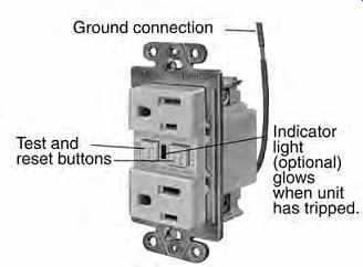
Fig. 44 Where it is desired to provide ground-fault protection at a single
outlet only, and thereby localize power interruption (rather than using a GFCI
circuit breaker on the entire circuit), a receptacle containing a ground-fault
interrupter, as illustrated, may be used. A test button is provided to permit
periodic testing, and a reset button reenergizes the receptacle after it has
tripped on ground fault and the fault has been cleared. (Courtesy of Eagle
Electric Manufacturing Co., Inc.)
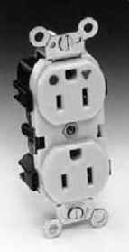
Fig. 45 Hospital-grade, insulated (isolated) ground receptacle used where
heavy duty is expected, and both reliability and freedom from electronic noise
are required. Hospital grade is denoted by a green dot on the upper left of
the receptacle face, and the insulated ground by an orange triangle on the
upper right. (Some manufacturers make the entire receptacle orange.) (Photo
courtesy of Leviton Manufacturing Co.)
A switch incorporating a solid-state rectifier is readily available that gives high/off/low control for incandescent lamps and costs very little more than an ordinary switch. Typical applications are in areas where a lower illumination level is often acceptable and always desirable as an energy-conserving measure. In high-security areas where an easily defeated normal key-operated switch is inadequate, a tumbler lock-controlled unit can be used. Loads that can be timed out, such as bathroom heaters and ventilating fans, can be controlled by a spring wound timer switch, as illustrated in Fig. 46 (which also illustrates a few common switch types). Figure 47 shows two common switch designs in cutaway, revealing their construction and operating mechanisms. A solid-state switch with adjust able time delay is shown in Fig. 48.
Thanks to miniature electronics, a programmable switch is available that fits into a wall-outlet box in lieu of an ordinary switch. The unit acts as a solid-state 15-A switch and can be readily programmed to switch the controlled circuit or device at preset times (see Fig. 48).
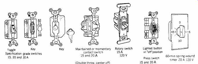
Fig. 46 A few of the most common wiring device switches, generally installed
in a small wall box and used for control of lighting circuits.
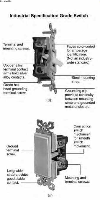
Fig. 47 Cutaway drawing of two common wall-switch designs showing operating
mechanisms and construction details. (a) Conventional toggle design. (b) Rocker
plate design. (Drawings courtesy of Eagle Electric Manufacturing Co.)
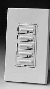
Fig. 48 Solid-state adjustable electronic switch timer that mounts in a common
wall-switch box. The unit switches off, with delay adjustable from zero to
15 minutes in five discrete steps.
Units such as these can control incandescent and fluorescent lamps and small motors. They are applicable where either direct manual control or occupancy sensors are inapplicable. (Photo courtesy of Leviton Manufacturing Co.)