AMAZON multi-meters discounts AMAZON oscilloscope discounts
(cont. from part 1)
9. TRANSFORMERS INDOORS: SELECTION
When transformers are installed indoors, they are subject to stringent National Electrical Code (NEC) regulations that are designed to make the installations intrinsically safe. These regulations are detailed in NEC Article 450. The essential considerations are presented herein.
(a) Oil-Insulated Transformers
These present a fire hazard when installed indoors because flammable oil can spread from a tank leak or rupture. To prevent this, most oil-filled trans formers must be installed in a fire-resistant vault, the construction of which involves substantial cost.
(See NEC Article 450 for exceptions.) Advantages offsetting this cost are an oil-filled transformer's small size, low first cost, low losses, long life, excel lent electrical characteristics, low noise level, and high overload capacity. Despite these, the vault requirement typically restricts oil-filled units to industrial facilities and other structures where electrical considerations favor their use.
(b) "Less-Flammable" Liquid-Insulated Transformers
Transformers rated 35 kV or less that are insulated with a liquid whose fire point is not less than 300ºC (572ºF) ("less-flammable" liquid) may be installed indoors without a vault. A liquid confinement area is required, plus either a fire-extinguishing system or restrictions on the combustibility of the building's contents. The insulating liquids used are special types of silicones and hydrocarbons, and the trans former installation must meet all requirements for the specific liquid involved. Selection of these units achieves the electrical and physical advantages of oil-insulated units without the cost of vault construction and installation. The first cost of the units depends upon the fluid type and the specific electrical characteristics required. In general, they are somewhat less expensive than nonflammable fluid insulated units with similar electrical ratings.
(c) Nonflammable Fluid-Filled Transformers
Certain nonflammable liquid coolants, called askarels, generally containing polychlorinated biphenyl (PCB), were once very widely used. However, since 1979, use of PCB coolants in new equipment has been banned by federal regulation due to their negative ecological impact, and existing units are gradually being phased out. Newer nonflammable fluid cool ants have increased the price of these transformers considerably (Table 4). Such units, nevertheless, have most of the advantages of oil-filled units and do not require a vault unless the voltage is very high. They do, however, require a sump or catch basin of sufficient capacity for all of the contained liquid. This and the high first cost are the negative aspects of this design.
(d) Dry-Type Transformers
These are the transformers of choice in the majority of indoor installations, despite having shorter life, higher losses, higher noise level, greater weight, and larger size than liquid-filled units. The principal advantages are simplicity of installation and almost unrestricted choice of location. As explained previously, using an underrated transformer (220ºC [428ºF] system, 80ºC [144ºF] rise), can reduce losses (heat) and extend life. Also, for a price premium, the noise level can be reduced.
Table 4 gives a comparison of the installed costs for the four classes of transformers discussed in this section.
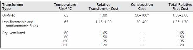
TABLE 4 Relative Installation Costs for a 300- to 1000-kVA Transformer
10. TRANSFORMER VAULTS
A transformer vault is basically a fire-rated enclosure provided because of the possibility of fire caused by rupture of an oil-filled transformer case.
This should not, however, be construed as implying that transformers are hazardous or delicate devices prone to faults. On the contrary, transformers are extremely tough, sturdy, long-lived, and capable of sustaining large and prolonged overloads. They are among the most reliable elements of an electrical system. However, faults do occur, and an oil-filled transformer is a potential fire hazard.
Transformer vaults should be located, to the extent possible, where they can be ventilated using the outside air without flues or ducts. The combined net area of all ventilating openings (gross area less screens, louvers, etc.) should be as noted in the preceding section: not less than 3 in.^2/kVA (1935 mm^2/kVA) of transformer, but in no case less than 1 ft 2 (0.09 m^2). Further ventilation recommendations plus details of enclosure construction materials, fire rating, door and sill details, and other relevant design information are provided by NEC Article 450.
11. SERVICE EQUIPMENT ARRANGEMENTS AND METERING
Metering must be provided ahead (electrically) of the building's service entrance switch(es). The metering is accomplished either at the utility or the facility voltage, and either at the service point or inside the building. The choice is generally left to the owner, with the understanding that interior meter equipment must be readily accessible to utility personnel. Although in increasingly large numbers of facilities regular meter reading is accomplished remotely, the meter equipment must still be avail able for utility company inspection and service.
If high-voltage service is purchased, then transformers and all other equipment beyond the service connection will be furnished by the owner.
Conversely, if low-voltage service is purchased, all the equipment necessary to provide such low volt age is furnished by the utility. As might be expected, the billing rates for low-voltage service are higher than those for high-voltage service in order to compensate the utility for the cost of providing and maintaining the needed step-down transformer and associated equipment. Therefore, it is often advisable for the owner of a large facility to investigate the economics of purchasing power at high voltage. Because many owners are not equipped to maintain high-voltage equipment, arrangements can sometimes be made to pay the utility to provide and maintain transformers while taking the cost advantage of high-voltage service.
For a single-occupant building or a building in which electric energy is included in the rental charge, only a single meter is necessary.
Provision for such metering may be provided in the main switchboard, or the meter may be independently mounted. In both cases, the meter is furnished and installed by the utility company.
Where submetering is required, such as in apartment houses, banks of meter sockets are installed to accommodate the multiple meters. Federal regulations forbid master metering in new multiple-dwelling constructions because it encourages energy waste (Fig. 7). Sub-metering should be considered in any facility where the energy consumption of specific building systems is of interest to conservation and/or ongoing commissioning efforts.
A low-voltage underground service detail as it would appear on a set of contract drawings, including relevant details, is given in Fig. 8. Note that here the service switch and meters are separately mounted.

Fig. 8 Typical electrical plan and details of an underground low-voltage service
(600-V class) to an industrial facility. Note that the portion of underground
service beneath the building must be encased in concrete. A service transformer
(if required) could be mounted on the utility pole or on a pad at the property
line.
12. SERVICE SWITCHES
The purpose of electric service switches is to disconnect the normal service to the building. (See Section 28.21 for a discussion of emergency electric ser vice.) In the event of a fire, for example, the switch can be used to ensure that no electrical hazard will face firefighters. This disconnecting apparatus must be located at a readily accessible spot near the point where the service conductors enter a building. If such a location is not feasible, service conductors may be run in concrete encasement under a building-and are considered "outside the building" up to the point at which they emerge from the floor in the building (see Fig. 8). At that point, the ser vice disconnect switch must be installed. The service switch or, more accurately, the service-disconnecting means may comprise between one and six properly rated switches. These are frequently assembled into a switchboard. Before discussing switchboards, however, a description of switches, circuit breakers, and fuses (the components of which switchboards are constructed) is in order.
13. SWITCHES
Traditional electrical switching devices are discussed in this and the following two sections. Mechanical switches close and open an electric circuit by physically moving two electrical conductors into contact with each other to close the circuit and physically separating them to open the circuit. The motive force can be supplied by hand, an electrical coil, a spring, or a motor; the device name may change accordingly, but the action is the same. Solid-state switches perform the same electrical switching function but by a completely different process, without moving parts. They are discussed in Section 16.
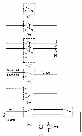
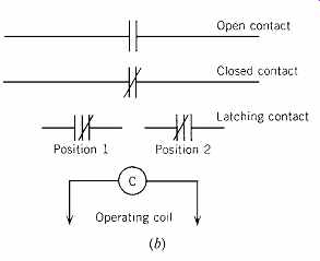
Fig. 9 (a) Typical switch configurations. Note that switches are always shown
in the open position. (b) Graphic representation of switch (contact) positions
in a contactor or relay. Note that a latching contactor shows the switch in
one of two positions to indicate the latching nature of the contactor.
(a)
(i) Single-pole single-throw switch.
(ii) Two-pole single-throw switch.
(iii) Three-pole and solid-neutral (3P and SN) switch.
(iv) Single-pole double-throw switch (also called, in small sizes, a 3-way switch).
(v) Single-pole double-throw switch with center "off" position (in control work called a hand-off automatic switch).
(vi) Use of two single-pole, double-throw (3-way)
switches for switching a lighting circuit from two locations
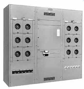
Fig. 7 Three-section commercial submetering switchboard comprising a center
service-entrance section rated 4000-A, 3-phase, 480-V maximum, equipped (usually)
with a main switch or circuit breaker. Each of the end cubicles will accept
six tenant meters, each on a 320-A 3-phase circuit, maximum, protected by an
integral circuit breaker or fused switch. Tenant wiring enters the top or bottom
of the board. Switchboards of this type can be installed on every floor of
a large multitenant commercial office building. (Photo courtesy of Cutler-Hammer.)
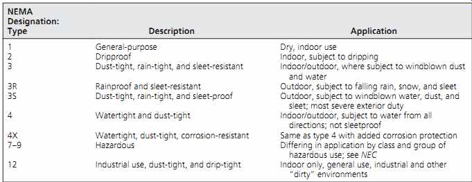
TABLE 5 Control Equipment Enclosures
An electrical switch is rated by current and volt age, duty, poles and throw, fusibility, and enclosure.
The current rating is the amount of current that the switch can carry continuously and interrupt safely.
Switches intended for motor control are also rated in horsepower (kW). The voltage rating of a switch is noted, as for other electrical equipment, by volt age class. Thus, a switch may be rated 250 V, 600 V, or 5 kV, as required. Switches intended for normal (occasional) use in lighting and power circuits are called general-duty safety switches. Switches intended for frequent interrupting, high-fault currents, and ease of maintenance are rated HD for heavy duty.
Figure 9a should clarify what is meant by the number of poles and throws of a switch. Unless otherwise noted, a switch is assumed to be single throw. Because the NEC states generally that the grounded neutral conductor of a circuit should not be broken, most switches carry the neutral through unbroken by means of a solid link within the switch.
This gives rise to the term solid neutral (SN) switch.
Switches are available in 1-, 2-, 3-, 4-, and 5-pole construction. Poles are indicated by a "P"; thus, 3 pole is written "3P," and so on.
A switch may be constructed with or without provision for fusing. If provided, the switch is fusible; if not, the switch is nonfusible. All individual enclosed switches are mounted in an appropriate cabinet. NEMA standardized the nomenclature and application of enclosures for all electrical control equipment, of which switches are only one item.
Summarizing, the following adequately describes a switch: switch, HD, 3P & SN, 200A/150AF, 600 V, in NEMA 12 enclosure. This "translates" as a heavy-duty switch, 3 poles and solid neutral, 200 amp rating with 150-amp fuses, 600-V rating, in an industrial use enclosure (Table 5). Such a switch is illustrated in Fig. 10.
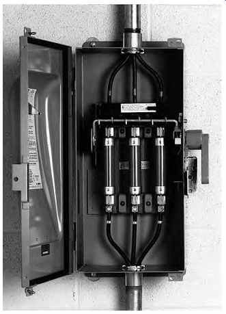
Fig. 10 The internal construction of a heavy-duty, fused, 3-pole, 3-wire switch
in an industrial NEMA 12 enclosure. Note the gasketing on the inside of the
cover, which seals the sheet steel box and makes it usable in environments
containing lint, dust, dirt, sawdust, and the like. The external handle is
a double lockable indicating type for safety. (Courtesy of Siemens Energy & Automation,
Inc.)
14. CONTACTORS
A contactor is a switch. Instead of a handle operated, movable blade, a contactor uses contact blocks of silver-coated copper, which are forced together to make (close) or are separated to break (open) a circuit. The common wall-mounted light switch is a small, mechanically operated contactor.
A relay is an electrically operated contactor. Most contactors are operated by means of an electromagnet that causes the contacts to close. They open either by spring action or by gravity.
Contactor terminology is somewhat different from that of switches. Its condition when deenergized is its normal state. Thus, a contactor whose contacts are open when the coil is not energized is referred to as normally open (NO), whereas a contactor whose contacts are closed when deenergized is referred to as normally closed (NC). Units intended for motor connection are called motor starters and are discussed in Section 26. Current, voltage, and number of poles have the same nomenclature for contactors and relays as for switches.
The great advantage of contactors over switches is their facility for remote control. Switches must be manually thrown-or, in very special cases, thrown by a motor. The magnetic contactor, by contrast, is inherently a remotely controlled device, making it ideal for myriad control functions. It can be controlled by a manual or remote pushbutton or by automatic devices such as timers, float switches, thermostats, pressure switches, and so on. Because control can be both remote and automatic, contactors are universally used in the control of lighting, heating, air conditioning, motors, and the like. A graphic representation of contactors is shown in Fig. 9b.
15. SPECIAL SWITCHES
Many special types of switches are available. Most of these types are beyond the scope of this book, except for the following, which are used extensively in building design work.
(a) Remote-Control (RC) Switches
A contactor that latches mechanically after being operated is known as a remote-control switch. It differs from a relay in that the latching operation performs the dual function of latching the contacts and disconnecting the electric circuit. To unlatch the contacts, the electric circuit must be reenergized. Such a device is therefore also known as an electrically operated mechanically held contactor. This characteristic is advantageous where the position of the contacts will be maintained for a long period (as in a lighting control circuit) and it is undesirable to hold the contacts by the continuous energizing of a coil, as would be required with an ordinary relay.
A typical unit is shown in Fig. 11, and a typical application is shown in Fig. 28.13. A common application of these switches is for controlling a "block" load, such as exterior lighting, whole-floor or whole-building lighting, and the like.
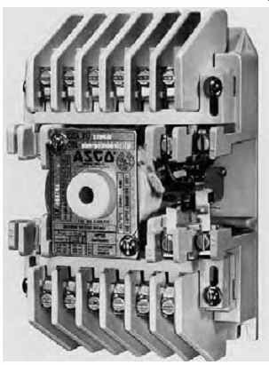
Fig. 11 This remote-control switch (mechanically held, electrically operated
contactor) is a 12-pole, 20-A, 600-V unit measuring approximately 7 in. H ×
6 in. W × 4 in. D (178 × 150 × 100 mm), making it suitable for stud-wall mounting.
Compact solid-state control modules are available that mount directly onto
the unit and convert it to a flush, wall-mounted multicircuit programmable
controller (see Section 16). (Courtesy of Automatic Switch Co.)
(b) Automatic Transfer Switch
This device, which is an essential part of all emergency and standby power arrangements, is basically a double throw switch-generally 3-pole-so arranged that on failure of normal service it automatically transfers to the emergency service. When normal service is restored, it automatically retransfers to it. (Retransfer can also be arranged to have a preset minimum delay, or it can be entirely manual.) The switch control is accomplished by voltage sensors that sense the condition of the service and operate the switch accordingly. Auxiliary devices can be added to the basic switch, the most common being emergency generator starting equipment.
Figure 12 illustrates a typical unit. Transfer switches used in uninterrupted power supplies are normally solid-state devices because these involve no switching time lapse.
(c) Time-Controlled Switches
This category includes all switches whose operation is time-based. The timer can be either the familiar electromechanical device consisting of a low-speed miniature drive motor, to which some type of contact-making device is physically connected, or it can be a solid-state electronic timer, which in turn controls either a relay or a solid state switch. The latter arrangement is the basis of all modern programmable time controls (Section 16), which find wide application in lighting control (Sections 15.14 and 30.27), energy management and automated building control (Sections 25.13 and 30.28), and clock and program systems.
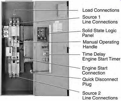
Fig. 12 Automatic transfer switch with solid state logic. The unit can be
operated manually if required. It is equipped with engine-starting contacts,
auxiliary contacts for monitoring, electrical safety interlocks, and automatic
differential voltage sensing on the normal source. An 800-A, 3-phase unit of
this design, in a NEMA indoor sheet metal enclosure, measures 73 in. H × 26
in. W × 21 in. D (1.9 × 0.7 × 0.5 m) and weighs approximately 600 lb (272 kg).
(Photo courtesy of Cutler-Hammer.)
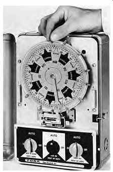
Fig. 13 Time switch arranged for three different types of control functions
that are applicable to different types of load: (1) full photocell control-security
lighting; (2) dusk "On," preset "Off"-signs, parking lots;
(3) preset on, off-interiors. This unit's dial is a 7-day calendar type that
permits setting a different schedule for every day of the week. The dial is
not astronomical (solar) because all the turn-on functions are either photocell
or time-of-day controlled. Solar dials are useful when photocell control is
not used because sunrise and sunset times vary with the season. (Courtesy of
Tork, Inc.)
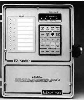
Fig. 14 Programmable time switch. This unit, which measures 9.5 in. H × 8
in. W × 4.5 in. D (240 × 200 × 115 mm) in its cabinet, permits independent
programming of eight 20-A, 240-V circuits. Each circuit (channel) can be arranged
for multiple on- off daily operations and can be programmed on a 7-day-a-week
basis, with special 365-day functions such as automatic daylight saving time
adjustment. (Courtesy of EZ Controls.)
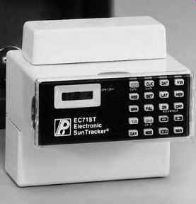
Fig. 15 This unit controls two 15-A, 240-V circuits. The built in astronomical
feature automatically adjusts the on-off setpoint according to sunset and sunrise
throughout the year. (Courtesy of Paragon Electric Co., Inc.)
Motor-operated timers (other than hand wound types) depend for their accuracy on power line frequency, have moving parts that wear, must be reset after power outages (although some units have spring-wound reserve power motors), and become cumbersome and expensive with an increase in the number of controlled events.
Electronic units are small, cool, quiet, independent of line frequency for accuracy (in many designs), able to carry through outages when equipped with a standby battery, and virtually unlimited in their event-control capacity. They have largely replaced the older mechanical design except for the simplest applications (Figs. 26.13, 26.14, and 26.15).
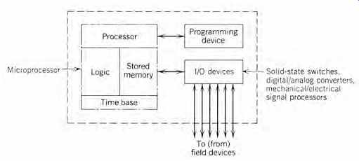
Fig. 16 Block diagram of a programmable controller. These devices are designed
to supervise field conditions continuously and are therefore used in industrial
applications as well as for lighting and environmental system control.
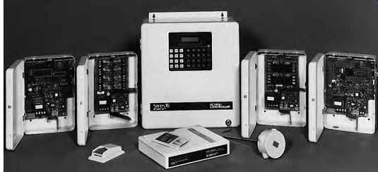
Fig. 17 Programmable controller (center) designed for use as an energy-monitoring
and building system control device. The basic unit accepts up to 16 analog
inputs, such as illuminance, temperature, kW demand load, time signals, central
control signals, and the like. It processes data according to its current program
(note the programming keypad) and can signal and control up to 16 outputs.
Additional functions available include time-of-day switching, including astronomical considerations, and duty-cycle load switching for electric demand control. The controller is approximately 14 in. W × 16 in. H × 6 in. D (355 × 410 × 150 mm) and is arranged for surface mounting. On either side are accessory communication and relay modules. In the foreground are application software and typical sensors. (Photo courtesy of Paragon Electric Co., Inc.)
16. SOLID-STATE SWITCHES, PROGRAMMABLE SWITCHES, MICROPROCESSORS, AND PROGRAMMABLE CONTROLLERS
A solid-state switch is an electronic device with a conducting state and a nonconducting state, corresponding to a conventional switch in its closed and open positions. The change between the two states is accomplished by the application of a control signal (voltage). The change of state is instantaneous and noiseless, and occurs without arcing. The current ratings of solid-state switches are approximately the same as those of their mechanical counterparts, ranging from fractions of an ampere to hundreds of amperes. Voltage ratings are usually limited to secondary systems values (0 to 600 V) due to the nature of the semiconductors comprising the active elements of these switches, although higher-voltage equipment is available for special applications.
If an electronic timing device is added to a solid state switch, a time-controlled electronic switch is created that functions exactly like the electromechanical time-based switches described in Section 15. These solid-state switches are independent of the utility line frequency for time control, and there are no moving parts to wear out. If a small, programmable memory circuit, in the form of an erasable programmable read-only memory (EPROM) chip is added, the device becomes a programmable time switch. The simplest of these are single-circuit 15-A devices intended to replace common wall switches (see Fig. 48). A more complex unit (corresponding roughly to the electromechanical unit shown in Fig. 13, but much more flexible) is shown in Fig. 14. Addition of a read-only memory (ROM) chip preprogrammed with astronomical information (sunrise-sunset) for a particular latitude converts the switch to a "sun tracker." Such a switch is particularly applicable to control circuits with year round dusk-to-dawn control (see Fig. 15).
A preprogrammed device, until reprogrammed, gives fixed, invariable instructions to a (multichannel) switch, as is the case with a programmable time switch. If a microprocessor (i.e., a logic/memory device programmed to respond according to a particular algorithm [control plan] to given input signals) is installed, a readily reprogrammable controller results (Figs. 16, 17, and 18). By definition, a programmable controller is an electronic device that uses a programmable memory chip for internal storage of instructions that in turn implement specific functions such as logic, timing, counting, and so on.
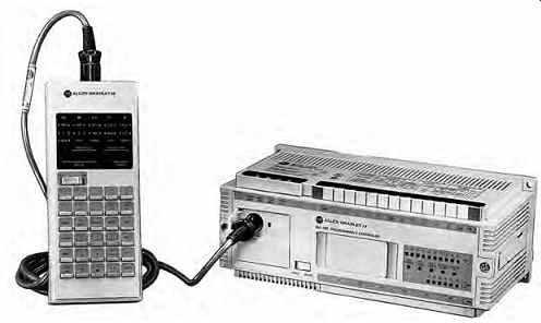
Fig. 18 General-purpose programmable controller. The processor unit contains
the central processing unit (CPU), random access memory (RAM), and power supply.
Peripherals include the illustrated hand-held programming unit and EEPROM (electrically
erasable programmable read-only memory) module, and various computer/software
interfaces (not shown). The unit illustrated, which measures approximately
10 × 9 × 3 in. (255 × 230 × 75 mm), has 16 input/output (I/O) circuits and
an 885-word memory. It is readily adaptable to a variety of automated control
processes in manufacturing, building control, and material handling. (Courtesy
of Allen-Bradley Co.)
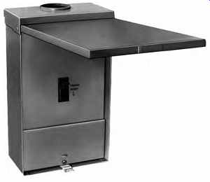
Fig. 19 Raintight NEMA type 3R outdoor circuit breaker enclosure. This is
the type usually intended when "weatherproof" is specified. (Courtesy
of General Electric, U.S.A.)
The internal control/memory is frequently referred to as a microprocessor; with respect to the overall programmable controller, it acts as a central processing unit (CPU). The programmable controller is therefore a special type of computer. It differs from a conventional computer in that its program is relatively short and exists in hardware (a micro processor), whereas a computer reads its program, which can be very lengthy, into its memory from software. Furthermore, the programmable controller is designed for a specific function, whereas a conventional computer is a general-use calculating device that processes almost any type of software.
Programmable controllers have all but replaced the ubiquitous hard-wired relay panel in applications such as industrial control, elevator control, process control, and the like, because of the ease with which such a controller can be reprogrammed (in lieu of rewiring a relay panel), the speed and accuracy of control, and the vastly increased complexity possible. See Section 30 for definitions and for an explanation of the application of these devices to building control.
17. EQUIPMENT ENCLOSURES
Proper NEMA nomenclature, descriptions, and applications for the more common enclosures are found in Table 5. It is important to note that there is no enclosure described as WP or weather proof. Equipment intended for outdoor use should be specified for installation:
1. In a type 3R enclosure to protect against rain (Fig. 19)
2. In a type 3S enclosure to protect against wind driven rain and sleet
3. In a type 4 enclosure to protect against rain, wind-driven rain and sleet, plus splashing and condensation.
Note also that the type 12 industrial enclosure is similar to type 1 except that it is gasketed for dust and drip resistance and therefore is well applied in all "dirty" indoor environments, including those in commercial and institutional spaces (see Fig. 10).
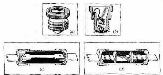
Fig. 20 Plug-type fuses are made in two physical types. (a) The nonrenewable
type with a standard ( Edison) base screws directly into a standard socket.
(b) Nonrenewable NEC type S fuses have a smaller base than type (a) and therefore
require an adapter to fit into a standard socket. The adapter is current-rated
and nonremovable. This prevents deliberate or accidental use of a type S fuse
of incorrect rating. Type S is required in new construction where plug fuses
are used. Both fuses shown are nonrenewable and must be replaced after blowing.
The type S fuse shown in (b) is a dual-element time-delay fuse. Cartridge fuses
are available in a variety of designs. Illustrated are (c) the nonrenewable,
single-element type and (d) the nonrenewable, dual-element, time-delay type.
Because fuses are inherently very-fast-acting devices, time delay must be built
into a fuse to prevent blowing on short-time overloads such as those caused
by motor starting. A dual-element fuse as shown in (b) allows the heat generated
by temporary overloads to be dissipated in the larger center metal element,
preventing fuse blowing. If the overload reaches dangerous proportions, the
metal will melt, releasing the spring and opening the circuit. The notched
metal portions of the fuse element, at both ends of the dual center element,
provide short-circuit protection. The time required to clear (blow) a fuse
is generally inversely proportional to the amount of current. In renewable-cartridge
fuses, the spent (blown) element is replaceable, reusing the original outer
cartridge and blade connectors.
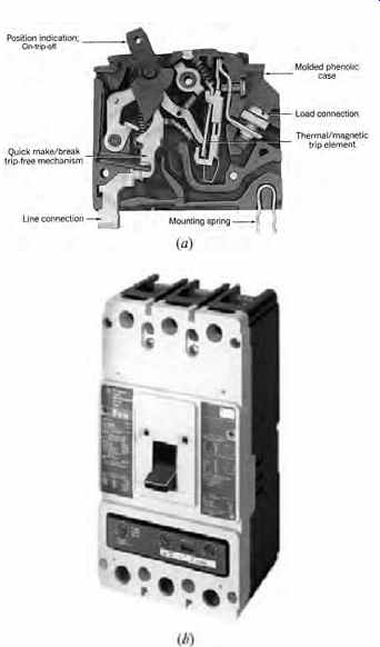
Fig. 21 (a) Essential elements of a plug-in-type molded-case circuit breaker
are shown in cutaway. Details vary with breakers designed for specific applications.
The unit shown is typical of breakers in the 50- to 100-A size. (Photo courtesy
of The Square D Company.) (b) Heavy-duty molded-case circuit breaker, 400-A
frame, 2- to 4-pole, 240-600 V. This circuit breaker is available with either
a standard thermal-magnetic trip or an adjustable electronic trip with ground
fault protection. Among the accessories available are auxiliary contacts, shunt
trip, undervoltage release, and an electrical solenoid operator that permits
remote control of the breaker. The unit is suitable for individual or panel
board mounting. A typical 3-pole unit measures 5½ in. W × 10 in. H × 4 in.
D (140 × 255 × 100 mm) and weighs about 12 lb (5.5 kg). (Photo courtesy of
Cutler-Hammer.)
18. CIRCUIT-PROTECTIVE DEVICES
To protect insulation, wiring, switches, and other apparatus from the destructive effects of overload and short-circuit currents, an automatic means for opening the circuit is required. The two most common devices employed to fulfill this function are the fuse and the circuit breaker, the latter frequently abbreviated c/b.
(a) Fuses
The fuse is a simple device consisting of a fusible link or wire of low melting temperature that, when enclosed in an insulating fiber tube, is called a cartridge fuse and, when enclosed in a porcelain cup, is known as a plug fuse. Figure 20 shows common types of fuses. Plug fuses, such as those in residential use, are rated 5 to 30 A, 150 V to ground, maximum. Cartridge fuses of various designs are available up to 6000 A and 600 V.
(b) Circuit Breakers
A circuit breaker is an electromechanical device that performs the same protective function as a fuse and, in addition, acts as a switch. Thus, it can be used in lieu of a switch-and-fuse combination to both protect and disconnect a circuit. Most circuit breakers are equipped with both thermal and magnetic trips.
The thermal trip acts on overload, whereas the magnetic trip acts on short circuit. These thermal and magnetic actions have inverse-time characteristics: that is, the heavier the overload, the faster the trip action. Modern circuit breakers in commercial and industrial applications are frequently equipped with solid-state electronic tripping control units, which provide fully adjustable overload, short circuit, and ground-fault protection.
Air-circuit breakers are available in two types: the molded-case breaker and the large air-circuit breaker. Molded-case breakers consist of a complete mechanism encased in a molded phenolic case. A light-duty molded-case 50-A frame, plug in circuit breaker is illustrated in Fig. 21a. The molded-case breaker shown in Fig. 21b has a 400-A frame and can be equipped with an adjustable electronic tripping unit, ground fault trip, plus other features formerly available only on large air circuit breakers. The large air-circuit breaker is a more complicated and highly adjustable device that can be used in applications that preclude the use of molded-case breakers. A modern solid-state adjust able trip controller for a large air-circuit breaker is shown in Fig. 22, along with a circuit breaker with a similar solid-state trip unit.
All breakers can be equipped with remote trip and auxiliary contacts, and all good breakers have trip-indicating handles and are trip-free (i.e., they will trip out harmlessly if closed on a short-circuited line). Low-voltage (600-V class) circuit breakers are available in frame sizes ranging from 50 to 4000 A and 1 to 3 poles. Their characteristics vary widely and are beyond the scope of this guide.
(c) Characteristics of Fuses and Circuit Breakers
Although both fuses and circuit breakers are circuit-protective devices, their characteristics differ markedly, as seen in the following comparisons.
Fuses-Switch-and-Fuse Combination
ADVANTAGES
Simple and foolproof Constant characteristics (no aging) Initial economy Very high interrupting capacity (IC) No maintenance Instantaneous; energy-limiting
DISADVANTAGES
Fuses are single-pole only Necessity for storage of replacement fuses Nonrenewable (one-time operation) Nonadjustable Non-indicating No electric or remote control a Not trip-free Circuit Breakers
ADVANTAGES
Usable as switches Multipole No storage of replacements required Resettable Indicates trip Trip-free Remote-control potential Adjustable
DISADVANTAGES
Low to medium IC, except for special units Periodic maintenance required High initial cost Complex construction changes with age a Can be accomplished with accessories.
These characteristics demonstrate that there is no single answer to the oft-posed question "Which are preferable-fuses or breakers?" The answer depends upon the specific application involved and is often based on highly technical factors requiring detailed analysis. Circuit breakers are generally used in lighting and appliance panelboards.
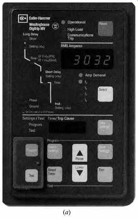
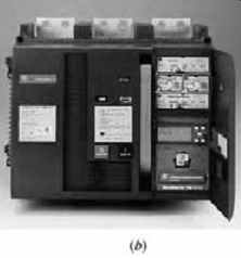
Fig. 22 (a) A multifunction microprocessor-based trip control unit for a large
circuit breaker. It provides true root-mean-square (rms) sensing of phase and
ground currents, selectable tripping characteristics, and trip alarm contacts.
In addition, the unit can be used to display and transmit information on phase
and ground currents. (Photo courtesy of Cutler-Hammer.) (b) Electrically operated
large air-circuit breaker with electronic microprocessor-controlled trip unit
and additional remote-control accessories. The illustrated unit, rated 2000
A, is shown before stationary (non-drawout) mounting in a switchboard. (Courtesy
of General Electric, U.S.A.)
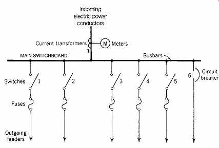
Fig. 23 One-line diagram of a typical switchboard. Switches are normally shown
in the open position. Switches must be on the line (supply) side of fuses.
Each line in a single-line diagram represents a 3-phase circuit. If circuit
breakers were used, the entire board would be composed of units as depicted
in circuit 6.