AMAZON multi-meters discounts AMAZON oscilloscope discounts
THE FIRST STEP IN DEVELOPING AN understanding of building electrical systems is to examine the means by which electric service is brought into a facility.
1. ELECTRIC SERVICE
The codes and standards that apply to electric service include:
1. National Electrical Code National Fire Protection Association; in particular, Section 230.
2. National Electrical Safety Code, published by the Institute of Electrical and Electronics Engineers (IEEE), www.ieee.org. This code is recognized by the American National Standards Institute (ANSI). It deals with clearances for overhead lines, grounding methods, underground construction, and related matters.
3. Standards of the utility supplying electric service.
Public utility franchises require only that service be made available at the private property line. Thus, service is normally connected to the utility lines at a mutually agreeable point at or beyond the property line. The service tap may be a connection on a pole with an overhead service drop or an underground service lateral to the building, or a connection to an underground utility line with a service lateral to the building. Electrical construction work on private property is usually at the owner's expense.
Under certain conditions, the owner can influence the type of service connection utilized by the electric utility company in conveying electric service to a site. This is often the case in large tract developments and in places where owners are willing to share some of the cost of better-grade construction.
Also, in many areas, the utilities themselves have instituted "beautification" programs in an effort to decrease the objectionable appearance of much of their equipment.
Service from a utility line to a building may be run overhead or underground, depending upon the following factors:
• Length of the service run
• Type of terrain
• Customer participation in the cost of service installation
• Service voltage
• Size and nature of the electric load
• Importance of appearance
• Local practices and ordinances
• Maintenance and service reliability
• Weather conditions
• Type of inter-building distribution, if applicable
2. OVERHEAD SERVICE
The principal advantage (to the utility) of overhead electric lines is low cost. Depending upon terrain and other factors, the cost saving of overhead com pared to underground installation has historically ranged from 10% to 50% (the latter when compared to direct burial cable installation). This accounts for the majority of installations being overhead. In recent years, special techniques in underground installation have lowered that cost, making it a reasonable economic alternative when its advantages are considered.
Where the length of the service run is several hundred feet (meters) or more, voltages higher than the facility's utilization level may be involved. This weighs heavily in favor of overhead lines, particularly with voltages exceeding 5000 V. Similarly, when terrain is rocky and the electrical load is heavy, the cost of underground installation rises sharply. Because overhead lines are easily maintained and repaired and faults easily located, service continuity with overhead lines is generally accept able. In areas with severe weather conditions, called heavy loading areas, where combinations of snow, wind, and ice increase the possibility of outages on overhead lines, underground service is preferable.
This is particularly true when even short service outages cause hardship or financial loss. Reliability of overhead service can be improved markedly by taking service from two separate, and preferably separated, overhead lines. A final decision on the type and location of electrical service will be made after meetings among the building's architect, the electrical engineer, and the electric utility's technical personnel.
Overhead cables are of several types: bare, weatherproof, or preassembled aerial cable. Bare copper cables supported on porcelain or glass insulators on crossarms are normally used for high voltage lines (2.4 kV and higher). Low-voltage circuits (600 V and below) are generally run on porcelain spool secondary racks using single-conductor (1/c) weatherproof cable. Preassembled aerial cable consists of three or four insulated cables wrapped together with a metallic tape and suspended by hooks from poles. This type of construction may be used for voltages of up to 15 kV (Fig. 1), and often proves to be more economical than cross-arm or rack installation and more resistant to damage from severe weather conditions.
A typical detail of an overhead electric service entrance to a multi-residence building is shown in Fig. 2.
3. UNDERGROUND SERVICE
The advantages of underground electric service are attractiveness (lack of physical and visual clutter overhead), service reliability, and long life. The principal disadvantage is high cost. To overcome this, utilities frequently use direct burial techniques that, by eliminating a raceway, reduce costs considerably. Because direct buried cable cannot be pulled out if it faults, as is the case with raceway-installed cable, restoration of service after a cable fault is time-consuming. It is recommended that the decision on which technique will be used be based upon the consideration of these factors:
• The cost premium for underground raceway installation, including hand holes if required
• The history of outages for direct burial installation by this installer, in the immediate area
• Cost and availability of repair service (utilities frequently will repair customer-owned under ground service laterals for a fee)
• Impact of electric service outage in terms of time delays, inconvenience, necessity of digging up lawns and paved areas, and cost impact in the case of a commercial facility
4. UNDERGROUND WIRING
The methods available for underground wiring are:
• Direct burial (Fig. 3)
• Installation in Type I, concrete-encased duct (Fig. 4a)
• Installation in Type II, direct burial duct (Fig. 4b).
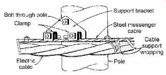
Fig. 1 Preassembled aerial messenger cables are carried by steel cables
clamped to poles.
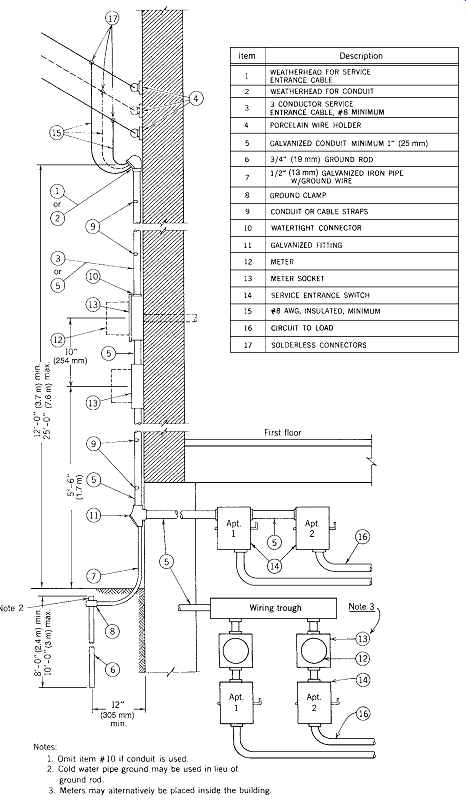
Fig. 2 Detail of typical overhead electric service to a four-family residence.
Note that meters in small residential buildings are frequently placed on the
exterior of the building. Alternatively, they can be installed inside, provided
that ready access is available or some type of remote meter-reading system
is installed.
The first alternative offers low cost and ease of installation, with the disadvantage regarding repairs stated previously. The second offers high strength and permanence, but at the highest price of the three. The last offers median cost but little strength. It is applicable only for installations on undisturbed earth and/or under light paving.
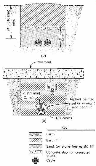
Fig. 3 (a) Technique for installation of direct-burial cable. (b) Under highways,
streets, and other high-load areas, cable should be installed in metal conduit.

Fig. 4 Underground duct installation. (a) The concrete duct bank should
have at least 6 in. (150 mm) of earth cover. (b) Heavy-wall duct should be
buried at least 24 in. (600 mm) in ordinary traffic areas and 36 in. (900 mm)
in areas subject to heavy traffic. Each layer is about 8 in. (200 mm) thick.
Nonmetallic duct (conduit) intended for under ground electrical use is commercially available in two wall thicknesses. NEMA (National Electrical Manufacturers Association) Type II with a heavy wall provides the physical protection required for direct burial installation with no concrete encasement. Type I is manufactured with a thinner wall and is intended for encasement in a minimum of 2 in. (50 mm) of concrete. Common trade names for asbestos-cement and fiber ducts are Transite and Orangeburg. Plastic conduit is referred to as PVC or simply as plastic.
Nonmetallic conduit is most frequently used without concrete encasement for low-voltage and signal wiring and with encasement for high-voltage wiring. It offers several advantages over steel conduit for underground work, such as lower cost and freedom from corrosion.
When underground electric wiring is duct installed and the run extends over several hundred feet (meters) (the exact distance depending upon the pulling tension), a pulling handhole or manhole is necessary. Handholes are used for low-voltage power and signal cables and for runs with a small number of cables. Manholes are used for high-voltage cables and where large duct banks must be accommodated.
Precast handholes and manholes are readily avail able in many standard sizes and are usually cheaper than field-formed and poured units.
Cable used in underground wiring must be specially manufactured and approved for that purpose. Type SE is the basic service entrance cable, constructed with a moisture- and flame resistant covering. When it is provided with moisture-proofing for underground use, the designation is SE type U, or simply USE. Underground cable for other than service runs is classified as type UF (underground feeder).
5. SERVICE EQUIPMENT
Referring to Fig. 27.1, note that a block labeled "transformer" is interposed between the high-volt age incoming utility lines and the secondary service conductors. This equipment item is required when ever the building utilization voltage is different from the service voltage. A transformer may be pole- or pad-mounted outside the building or installed in a room or vault inside the building, as discussed later.
6. TRANSFORMERS
A transformer is a device that changes or transforms alternating current (ac) of one voltage to alternating current of another voltage. Transformers used in building work consist essentially of an iron core on which are wound at least two coils: a primary (coil) winding and a secondary (coil) winding. A voltage impressed on the primary winding induces (through the iron core) a voltage in the secondary winding in proportion to the ratio of turns in the two coils. Thus, a step-down transformer has a larger number of turns in its primary winding than in its secondary winding, and a step-up transformer has the reverse. In theory, transformers are reversible, although in practice they are rarely used that way. Transformers cannot be used on dc.
A transformer typically is used to step down an incoming 4160-V service to 480-V for distribution within a building. Another transformer is then used to step down the 480 V to 120 V for use on receptacle circuits. Ordinarily, 120, 208, 240, 277, and 480 V are called low or secondary voltages, and 2400, 4160, 7200, 12,470, and 13,200 V are high or primary voltages.
Transformers are available in single-phase or three-phase construction. Transformer power capacity is rated in kilovolt-amperes (kVA). For a single-phase unit, this figure is the product of the full load current and the voltage. Because the volt ages on the primary and secondary are different, so are the primary and secondary currents-because the kVA remains constant.
For example, a single-phase 100-kVA, 2400/ 120-V transformer will carry at full load:
primary current =
100,000 VA 2400 V
= 41.6 A secondary current =
100,000 VA 120 V
= 832 A
That is, the ratio of primary to secondary current is exactly the reverse of the ratio of primary to secondary voltage, because their product, which is the transformer's kVA rating, remains constant.
Expressed in an equation, primary current × primary voltage
= secondary current × secondary voltage or Vp Ip = VS IS (26.1) where Vp is the primary voltage Ip is the primary current VS is the secondary voltage IS is the secondary current
Heat is generated by the passage of current through the transformer coils due to the winding cable resistance. This heat is transferred to the unit's cooling medium, where it is radiated or otherwise disposed of. The unit's cooling medium is a property of major importance. Transformers are either dry (air-cooled) or liquid-filled. The choice depends upon the required electrical characteristics, the proposed physical location of the trans former, and costs. Although detailed considerations are beyond the scope of this book, some selection criteria are presented in the following sections. In general, units rated above 5 kV are liquid-filled and units in the 600-V class are dry. Units installed indoors, except in vaults, are normally of the dry type, and are intended for general-purpose lighting and power circuits (Table 1). Load center transformers are installed in unit substations, both indoor and outdoor. Distribution transformers are mounted on a pole or on a concrete pad outdoors.
Substation transformers are large and are always concrete-pad-mounted.
The insulation class of a transformer affects its permissible temperature rise and operating temperature, and, as a direct result, its physical size, electrical power losses, overload capacity, and life.
The physical size of a transformer of a given kVA rating and voltage depends upon the type of insulation used. In order of decreasing physical size and increasing operating temperature, we have, for dry transformers, 105, 150, 185, and 220ºC (221, 302, 365, and 428ºF) systems that represent organic, inorganic (two types), and silicone insulating materials, respectively (Table 2).
Dimensional data for transformers vary considerably from one manufacturer to another. There fore, Table 3 is useful only for a concept of bulk volume and weight.
Although 220ºC (428ºF) system insulation transformers can withstand a 150ºC (270ºF) rise (see Table 2), some users specify 220ºC (428ºF) system insulation with a 115ºC (207ºF) rise or even an 80ºC (144ºF) rise; that is, a better grade of insulation is used with an underrated transformer. There are four advantages to this design decision:
• Longer life
• Higher overload capacity
• Lower operating cost
• Increased capability to withstand the heating effects of harmonics commonly found in commercial and industrial electrical systems
A 220ºC (428ºF) system transformer operated at full load continuously (an unusual situation) has a short life--estimated on the basis of accelerated aging tests to be between 3 and 10 years. The same class insulation transformer (220ºC [428ºF] system) rated at 80ºC (144ºF) has a life expectancy of more than 100 years. With respect to operating cost, the same issues apply here as with the selection of high-temperature insulation discussed in Section 27.8 and summarized in Table 27.2. The adage that you get what you pay for can be expressed here as follows: In return for a smaller, lighter, cheaper, and hotter transformer (220ºC [428ºF] system), there will be higher losses, and therefore a higher operating cost and a shorter life.
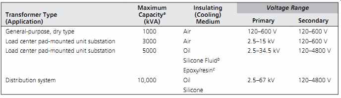
Table 1 Typical Transformer Data
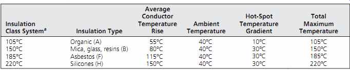
Table 2 Air-Cooled Transformer Electrical Insulation Temperature Ratings
(Based on 40ºC Ambient)
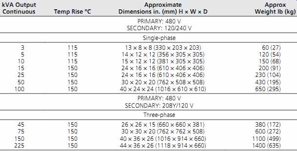
Table 3 Typical Dry-Type Transformer: Dimensions and Weights
It is good practice in buildings with a total transformer capacity in excess of 300 kVA to complete a calculation comparing the operating costs of various types of transformers in order to balance energy costs with necessary operating flexibility, reliability, and safety.
Such a calculation was performed assuming a daily/weekly operating cycle and loading that is representative of commercial use. The two trans formers studied were of the dry type, rated 750 kVA, one designed for an 80ºC (144ºF) rise and the second for a 150ºC (270ºF) temperature rise. At an energy cost of 7 cents per kWh, the lower energy waste of the more expensive 80ºC (144ºF) unit repays the first-cost differential in about 4 years.
A higher electric energy cost reduces the payback time, and vice versa. Beyond the payback period, the advantage is entirely on the side of the 80ºC (144ºF) unit. Using a 30-year life, 8% fixed capital cost, and 3% annual cost escalation, the life-cycle cost of the 80ºC (144ºF) unit is $10,000 less than that of the 150ºC (270ºF) unit. (At the assumed loading, even the 150ºC [270ºF] unit will probably last 30 years, the 80ºC [144ºF] unit much longer.) Furthermore, with a total permissible hot-spot temperature of 220ºC (428ºF), the location of the 150ºC (270ºF) rise unit must be very carefully chosen because it can create a serious heat generation and radiation problem.
To summarize, a transformer is specified by type, phase, voltages, kVA rating, sound power level, and insulation class. Thus, a 112.5-kVA, three phase, 480/120 to 208-V, air-cooled, indoor, dry type transformer with 220ºC (428ºF) insulation system and 115ºC (207ºF) rise, 45 dB (decibel) maximum sound level, represents an adequate transformer description. Sound ratings of trans formers, as well as installation techniques and acoustical treatment, are discussed in Part IV.
A service transformer bank is necessary when the facility utilization voltage is different from the utility voltage (Fig. 5a). A building design may call for a step-up, step-down arrangement when the service run is so long that the conductor cost, when run at a low voltage, would be excessive because of large cables. In such instances, the cost of the double transformer installation must be more than off set by the savings in feeder cost to be economically justifiable (Fig. 5b). More commonly, step-down transformers are the norm.
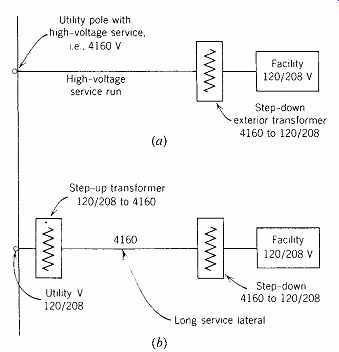
Fig. 5 Service transformer arrangements. (a) High-voltage service with
a step-down service transformer at the facility and (b) low-voltage service,
with transformation at both ends of a long service run.

Fig. 6 (a) Pad-mounted exterior transformers are neat, compact, and, if
sited properly, unobtrusive. Large units can be partially screened by shrubbery.
(b) When the size is such that visual screening becomes a problem, consideration
should be given to a structural screen such as a decorative brick wall.(Courtesy
of General Electric, U.S.A.)
7. TRANSFORMERS OUTDOORS
The advantages of an outdoor transformer installation are:
• No enclosed building space required
• Reduced probability of a noise problem within the building
• Lower first cost
• Ease of maintenance and replacement
• No interior heat production
• Opportunity to use low-cost, long-life, oil-filled units
Although an exterior installation comes with pluses, it is frequently easier to find space indoors (preferably in a basement) than to find a suitable exterior location. Noise may be more disturbing in the context of some available exterior spaces, such as courtyards, than with a basement location.
Costs can be high if long secondary voltage runs are required; heat can often be handled by louvers or areaways adjoining a basement, or even used beneficially if the transformer load is fairly constant.
Because exposure to direct sunlight decreases a transformer's rating by increasing its temperature, a shaded exterior location is preferable, but may be difficult to find. Furthermore, an exterior trans former, other than pole-mounted, is a questionable choice in an area with a high incidence of vandal ism, regardless of the sturdiness of construction.
Finally, the appearance of an exterior unit may be objectionable. This point has received much attention from manufacturers, and numerous designs have been developed that minimize aesthetic concerns (Fig. 6). The most popular type of exterior transformer installation is the pad mount. It has all of the advantages listed previously in addition to extreme simplicity of installation-it is set on a simple concrete pad. Consult manufacturers' catalogs for dimensional data.
8. TRANSFORMERS INDOORS: HEAT LOSS
When an indoor transformer installation is indicated, special consideration must be given to the transformer's heat-generating properties. Between 1% and 1½% of a transformer's load rating, depending upon the type, is converted to heat at full load.
For a 750-kVA, dry-type, 150ºC- (270ºF-) rise unit, 12 kW, or 41,000 Btu/h, of heat loss is generated at full load! Losses are lower for 80ºC- (144ºF-) rise units. Liquid-filled units have approximately the same losses as 80ºC- (144ºF-) rise dry units. Unless the heat can be used, sufficient ventilation-either natural or forced-must usually be provided to keep the transformer room's ambient temperature from exceeding 40ºC (104ºF).
Ventilation by natural convection is most desirable, requiring the transformer room be located on an exterior wall (adjacent to an areaway if the room is located below grade). The required size (the free area) for a ventilation opening is 3 in. 2/kVA (1935 mm^2/kVA) of capacity, plus an additional 1 in.^2/kVA (645 mm^2/kVA) for switchgear heat losses, if any. If a louver is used to protect the ventilation opening, the size of the opening must usually be doubled (total: 8 in.^2/kVA [5160 mm2/kVA]) because most louvers have a 50% free area. For good convection, it is desirable to divide the opening areas in half, placing one-half near the ceiling and the remaining half near the floor. To provide for future equipment removal, if an areaway in a basement installation is large enough, it may be useful to increase the over all opening area and make the louver removable for access. A bird screen is also desirable.
Because outside air temperature varies, it is advisable to use a temperature-controlled, adjust able louver. In extremely cold climates, heat loss from the electrical equipment may not be sufficient to warm the room in winter. In such instances, a unit heater should be installed in the room with a thermostat set at 55ºF (13ºC).