AMAZON multi-meters discounts AMAZON oscilloscope discounts
HISTORICALLY, USABLE ENERGY WAS MOST often produced by burning a fossil fuel such as coal or oil. The resultant heat energy was used directly as heat and light or converted by machines into motion. Only since the end of the nineteenth century, however, has this heat in turn been used to create another very usable form of energy-electricity. The partial substitution of nuclear for fossil fuels has affected only the heat production portion of this process. Beyond that point, the heat is utilized in the same manner to drive generators that produce electricity. It is well to remember that, in terms of consumption of natural resources, electricity is an expensive form of energy because the efficiency of the overall heat-to-electricity conversion, on a commercial scale, rarely exceeds 40%.
1. ELECTRIC ENERGY
Electricity is a form of energy that occurs naturally only in unusable forms such as lightning and other static discharges or in natural galvanic cells (which cause corrosion). The primary problem in the utilization of electric energy is that, unlike fuels or even heat, it cannot be readily stored and therefore must be generated and utilized in the same instant. This requires an entirely different concept of utilization than, for example, a heating system with its fuel source, burner, piping, and associated equipment.
The bulk of electric energy utilized today is in the form of alternating current (ac), produced by ac generators commonly called alternators. Direct current (dc) generators are utilized for special applications requiring large quantities of dc. In the building field, such a requirement was once almost universal for elevators because of the ease with which dc motors can be speed-controlled. Today, however, because fine speed control of ac motors is practical, ac motors are the driver of choice for modern elevators, with attendant energy savings and a reduction in machinery space requirements. Smaller quantities of dc, furnished either by batteries, photovoltaic (PV) equipment, or rectifiers, are utilized for telephone and signal equipment, controls, and other specialized uses.
2. UNIT OF ELECTRIC CURRENT--THE AMPERE
Electricity flowing in a conductor is called current, which is measured in amperes, abbreviated amp, amps, or simply A. When current is used in an equation, it is usually represented by the letter I or i.
It is convenient to establish an analogy between electrical systems and mechanical systems as an aid to understanding the characteristics of electricity. Current is a measure of flow and, as such, corresponds to water flow in a hydraulic system (Fig. 1). The analogy is not complete, however, because in a hydraulic system the velocity of water flow can vary, whereas in an electrical system the velocity of (electric) propagation is constant and may be considered instantaneous.
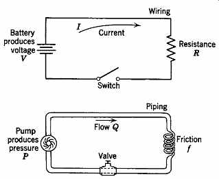
Fig. 1 Electric-hydraulic analogy. The circuits show that voltage is analogous
to pressure, current to flow, friction to resistance, wiring to piping, and
switches to valves.
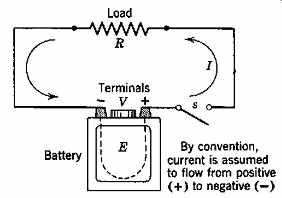
Fig. 2 Current flows in the electric circuit as a result of the voltage
(potential difference) V that exists between the terminals of the battery.
By convention, current direction is from positive (+) to negative (-) in the
circuit (and from - to + inside the battery).
3. UNIT OF ELECTRIC POTENTIAL--THE VOLT
The electron movement (and its associated energy, which constitutes electricity) is caused by creating a higher positive electric charge at one point on a conductor than exists at another point on the same conductor. This difference in charge can be created in a number of ways. The oldest and simplest method is by electrochemical action, as in a battery.
In the ordinary dry cell, or in a storage battery, chemical action causes positive charges (+) to collect on the positive terminal and electrons [i.e., negative charges (-)] to collect on the negative terminal.
Assume for the moment that nothing is connected to the battery terminals. There is a tendency for flow between the electrified particles concentrated at the positive and negative terminals. Potential difference or voltage is the name given to this tendency, or force. It is analogous to pressure in a hydraulic or pneumatic system. Just as the pressure produced by a pump or blower causes water or air to flow in a connecting pipe, the potential (voltage) produced by a battery (or generator) causes current to flow in a conductor connecting the terminals between which a voltage exists (Fig. 2). The higher the voltage (pressure), the higher the current (flow) for a given resistance (friction). Other means of producing voltage, both direct (dc) and alternating (ac), are discussed in Section 25.8. The unit of voltage is the volt, abbreviated V or v.
4. UNIT OF ELECTRIC RESISTANCE--THE OHM
The flow of fluid in a hydraulic system is resisted by friction; the flow of current in an electric circuit is also resisted. In a dc circuit this force is called resistance and is abbreviated R; in an ac circuit it is called impedance and is abbreviated Z. The unit of measurement is the ohm. The scientific convention of naming units after persons whose work is closely related to the field is followed here. Thus, the units ampere, volt, and ohm are derived from André Ampère, Alessandro Volta, and Georg Ohm.
Materials display different resistances to the flow of electric current. Metals generally have the least resistance and are therefore called conductors.
The best conductors are the precious metals-silver, gold, and platinum-with copper and aluminum being only slightly inferior. Conversely, materials that resist the flow of current are called insulators.
Glass, mica, rubber, oil, distilled water, porcelain, and certain synthetics exhibit nonconductive properties and are used to insulate electric conductors.
Common examples are rubber and plastic wire coverings, porcelain lamp sockets, and oil-immersed switches.
5. OHM'S LAW
The current I that will flow in a dc circuit is directly proportional to the voltage V and inversely proportional to the resistance R of the circuit. In ac circuits, the same relation holds true except that instead of dc resistance we use ac impedance. Expressed as an equation, this is the basic form of Ohm's law:
I V R
= (25.1)
Ohm's law is frequently written in another form:
V = IR (25.2)
which expresses the mathematical relationship that voltage is the product of current and resistance. This form has no intuitive or logical basis; therefore, remembering the form of Equation 25.1 will prove more useful. It clearly states the physical situation, that is, as a result of voltage V, a current I is produced that is proportional to the electric volt age (pressure) V and inversely proportional to the electric resistance (friction) R. If V increases, I will increase; if R increases, I will decrease.
Example 1 illustrates the application of Ohm's law. The example chosen is applicable to both ac and dc because the load device is purely resistive. When a load is purely resistive, resistance and impedance are equal. This is more fully explained in the subsequent discussion of alternating current.
EXAMPLE 1 An incandescent lamp having a hot resistance of 66 ohms is put into a socket that is connected to a 115-V supply. What current flows through the lamp (after it reaches operating temperature)?
SOLUTION I V R A == =
115 66 174 volts ohms.
(These values correspond to a typical 200-W general service incandescent lamp.) ¦ Hot resistance is mentioned in Example 25.1 because the electrical resistance of some materials changes with temperature. A typical example of this is a tungsten-filament lamp that when first turned on (cold) takes, for a fraction of a second, 10 to 15 times the steady-state hot filament current.
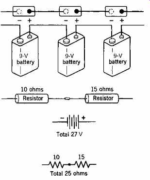
Fig. 3 Physical and graphic representation of a series connection of batteries
and resistors.
6. CIRCUIT ARRANGEMENTS
The two basic electric circuit arrangements are series and parallel. These concepts are the same for both dc and ac. As previously, the discussion focuses upon purely resistive circuits so that calculations are applicable to both dc and ac. In other than purely resistive circuits, ac circuit calculations are different and much more complicated than those for their dc counterparts.
(a) Series Circuits In a series arrangement the elements are connected one after another, that is, in series. Thus, resistances and voltages add. This is indicated graphically in Fig. 3. An electric circuit may be defined as a complete conducting path that carries current from a source of electricity to and through some electrical device (or load) and back to the source.
A current cannot flow unless there is a complete (closed) circuit. Due to the arrangement of components in a series circuit, the current is the same in all parts of the circuit. A somewhat more complicated circuit is shown in Fig. 4 and is analyzed in Example 25.2.
It is customary to refer to connection points on wiring diagrams by letters, as a, b, c, d, and so on.
The battery voltage may then be called Vab
= 12 V; the voltage across the load resistance, Vcd
= 11.5 V; and the resistance of the two wires rbc
+ rda
= 0.04 ohm. The positive and negative terminals of the battery are always shown.
EXAMPLE 2 The battery in Fig. 4 is rated at 12 V; the total line resistance (the total for both wire segments) is 0.04 ohm; the battery internal resistance is 0.01 ohm; and the load resistance is 1.15 ohms.
Determine (a) the current flowing in the circuit and (b) the voltage across the load (Vcd ).
SOLUTION (a) The current flowing is I V R V rrrr
==
+++ ab ab bc cd da
=
+++ 12
002 115 002 12 12 0.01 . . . .
==10 A (b) The voltage drop across the load is Vcd
= I × Rcd
= 10 × 1.15 = 11.5 V ¦
Series circuits find very limited application in building wiring because failure of any one load (such as a burned out lamp) will open the circuit (shutting off power to all loads on the circuit).
(b) Parallel Circuits
When two or more branches with loads are connected between the same two points, they are said to be connected in parallel or multiple. Such a parallel arrangement and its hydraulic equivalent are shown in Fig. 5. In the circuit of Fig. 6 it can be seen that the voltage across each load is the same, but the current in each load (branch) depends upon the resistance of that load. Parallel loads, in effect, constitute separate circuits. In this arrangement the total current in the circuit is the sum of the individual currents flowing in the branches-that is, I T
= I 1
+ I 2
+ I 3
Fig. 5 In a parallel connection the flow divides between the branches,
but the pressure is the same in each branch.
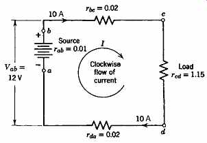
Fig. 4 A series circuit always contains a voltage source (here, the battery),
and a load (R). This circuit also shows the resistance of the connecting wires
for accuracy. Such resistances are normally neglected because they usually
are very small compared to the load resistance.
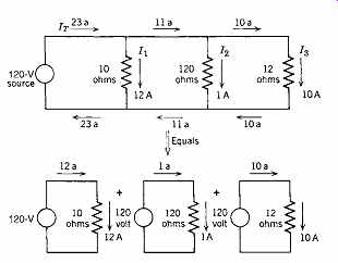
Fig. 6 Note that loads connected in parallel are equivalent to separate
circuits combined into a single circuit. Each load acts as an independent circuit
unrelated to, and unaffected by, the other circuits.
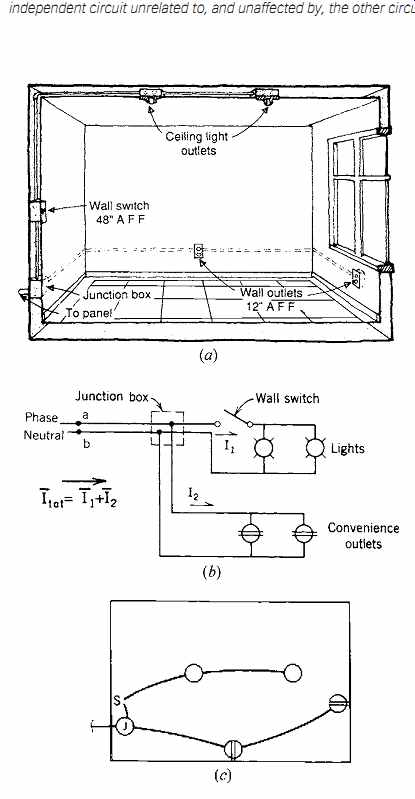
Fig. 7 Parallel groupings of ceiling lamp outlets and wall outlets are
in turn connected in parallel to each other. The circuit is shown (a) pictorially,
(b) schematically, and (c) as on an electrical floor plan. (The horizontal
bar over the currents I 1 and I 2 in (b) signifies the use of vectorial addition;
see Example 25.5.)
Notice in Fig. 6 that the total current flowing in the circuit is the sum of the currents in all the branches, but that the current in each branch is determined by a separate Ohm's law calculation.
Thus, in the 10-ohm load, a 12-A current flows, and so forth.
The parallel circuit is the standard arrangement in all building wiring. A typical lighting and receptacle arrangement for a large room is shown in Fig. 7. Here the lighting fixtures constitute one parallel (multiple) grouping, and the convenience wall outlets constitute a second parallel grouping. The fundamental principle to remember is that loads in parallel are additive for current and that each load has the same voltage across it.
One additional point is important to appreciate.
Remember from Ohm's law that current is inversely proportional to resistance. Thus, as resistance drops, current rises. Now look at the circuit of Fig. 7.
Normally, that circuit carries the (vector) sum of the currents in the two branches. (Vectorial addition is discussed in Section 25.11, Example 25.5c.) If, by some mischance, such as deterioration of the wiring insulation, a connection forms between points a and b, the circuit is shortened so that there is no resistance in parallel branch ab. The current rises instantly to a very high value, and there is a short circuit. If the circuit is properly protected, a fuse or circuit breaker opens and the circuit is deenergized.
If not, the heat generated by the very high current will probably start a fire.
7. DIRECT CURRENT AND ALTERNATING CURRENT
A flow of electric current that takes place at a constant time rate, practically unvarying and in the same direction around a circuit, is called a direct current (dc). Figure 25.8 shows dc voltages of 1.5 V positive polarity and 1.0 V negative polarity.
When the flow of current is periodically varying in time and in direction, as indicated by the symmetrical positive and negative loops, or sine waves, in Fig. 9, it is called an alternating current (ac). The distance along the time axis spanned by a positive and a negative ac loop is called one cycle.
The number of such cycles occurring in 1 second is known as the frequency of the ac current. Modern ac systems in the United States and Canada operate at a frequency of 60 cycles per second, or 60 hertz (after Heinrich Hertz). Thus, current at 60 hertz (abbreviated Hz) is delivered to the consumer. In Europe and much of Asia, 50-Hz distribution is standard.
An ac circuit differs from a dc circuit in a number of important respects and, because the normal current supply is 60 Hz ac, it is important to under stand ac terminology and usage. Instead of resistance, the corresponding parameter in an ac circuit is impedance, which is (also) measured in ohms.
Depending upon the circuit load, impedance can be markedly different from the dc resistance.
For an ac circuit, Ohm's law is
I V Z = (25.3)
where Z is the symbol for impedance. This book does not go into ac circuit calculations primarily because such calculations are not especially useful to the typical building designer. What is useful and important is an understanding of power and energy in both dc and ac circuits. These concepts are discussed in the following sections.
8. ELECTRIC POWER GENERATION--DC
With respect to the generation of large amounts of dc power, piezoelectric and thermoelectric effects can be ignored. Photovoltaic (PV) power generated from solar cells-as discussed in Section 29-is becoming increasingly important as a practical source of electricity for specialized uses and as part of green/carbon-neutral building design efforts.
This leaves the battery and the dc generator (along with PV) as everyday sources of dc electricity.
Because the dc generator is in reality an ac generator with a device (commutator) attached that rectifies the ac to dc, the battery is the major direct source of dc. (There are some special types of generators that produce dc directly, but their use to date has been extremely limited.) A discussion of the application of batteries for emergency and standby power supplies can be found in Section 28.
Another source of dc power is rectification of ac. This can be accomplished on any desired scale to provide as much dc power as there is available ac power. The principal application of dc in older buildings is for elevator motors. In many buildings dc is used for standby power. Small amounts of dc are also used for controls and telephones.
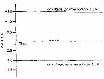
Fig. 8 Graphic representation of dc voltages with positive and negative
polarity.
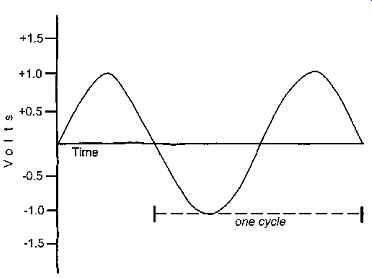
Fig. 9 Graphic representation of a pure single-frequency alternating current
(ac). The figure shown is a sine wave. Note that a complete cycle includes
both the positive and negative loops. The number of full cycles in 1 second
is defined as the frequency of the current (or voltage).
9. ELECTRIC POWER GENERATION--AC
Alternating current is produced commercially by an ac generator, generally called an alternator. Its prime mover may be any type of engine or turbine.
The process by which electricity is produced is illustrated in Fig. 10; it is based upon the fundamental discovery in 1831 by Michael Faraday of the principle of electromagnetic induction. Briefly, this principle states that when an electrical conductor is moved in a magnetic field, a voltage is induced in the conductor. The direction of movement deter mines the polarity of the induced voltage, as shown in Fig. 10.
If a conductor is formed into a coil and rotated in a magnetic field, a voltage of alternating polarity is produced, that is, alternating current. It does not matter whether the conductor or the magnet moves; the motion of the conductor and the field with respect to each other produces the voltage (see Fig. 11). It is only one step (that of commercial development) from this rudimentary ac generator to the large, powerful alternator that produces ac in a modern power plant. The frequency of the volt age generated is a function of the machine design and the speed at which it is driven. Normal genera tor frequency in the United States, as noted previously, is 60 Hz, whereas in Europe and the Mideast it is 50 Hz.
10. POWER AND ENERGY
It is critically important that the distinction between power and energy be clearly understood. All too frequently the terms are used interchangeably-which is incorrect and can lead to bad design decisions.
Energy is the technical term for the more common expression work. Power is the rate at which energy is used. For example, it takes a fixed amount of energy to lift a weight a given distance either quickly (in 5 minutes) or slowly (over 5 hours), but the faster it is lifted, the more power that is required. Energy is the product of power and time, that is, energy (work) = power × time (25.4) In practical terms, energy is synonymous with fuel consumption and, therefore, with cost (and resource depletion, for fossil fuels). Energy can be expressed as barrels (liters) of oil, cubic feet (cubic meters) of gas, tons (kilograms) of coal, kilowatt hours of electricity usage, and/or dollars of fuel cost. The outcome of energy efficiency efforts for buildings can be stated in terms of annual usage of oil, gas, and electricity or, alternatively, in terms of dollars spent for fuel or utilities. In technical terms, energy is expressed in units of Btu (calories), foot pounds (joules), and kilowatt-hours. Conversion factors between these (and other) units of energy are found in Appendix A. In terms of fuel, 1 kilo watt-hour (kWh) of energy is roughly equivalent to 0.5 lb (0.23 kg) of coal, 0.07 gal (0.26 L) of oil, 7.7 ft 3 (0.22 m3) of natural gas, and 8200 gal (31,000 L) of water in a hydroelectric dam.
Power is the rate at which energy is used or work is done (energy and work being synonymous). The term power implies continuity-that is, the use of energy at a particular rate, over a given, generally considerable, span of time. The concept of power necessarily involves the factor of time because it is, as stated previously, the rate at which work is done. Multiplying power by time yields energy consumption. Typical units of power in the I-P system are horsepower, Btu per hour, watt, and kilowatt. In the SI system, the corresponding units are joule per second, calorie per second, watt, and kilowatt. In physical terms, power is also the rate at which fuel (energy) is used. Thus, power can also be expressed as gallons (liters) of oil per hour, cubic feet (cubic meters) of gas per minute, and tons (kilo grams) of coal per day. (When using fuel figures, it is important to ascertain the assumed fuel-to-useful-energy conversion efficiency. When not stated, "energy content" [i.e., energy availability at 100% conversion efficiency] is assumed.) Most U.S. building codes are based upon site energy use, rather than source energy-making conversion efficiency a hidden (but important) issue.
11. POWER IN ELECTRIC CIRCUITS
The unit of electric power is the watt (W); 1000 watts is the commonly encountered kilowatt (kW). Both units are commonly used in building design situations depending upon the magnitude of the load-as in a 100-W incandescent lamp, or a 5-kW resistance heating coil. The power input in watts to any electrical device having a resistance R and a current I is given by the equation
W = I 2 R = (I) (IR) (25.5)
where W is wattage. This is true for both dc and ac circuits. Because the resistance of a device or load is generally not known, whereas the circuit voltage and current are known, it would be preferable to be able to calculate power using these latter two quantities. This can be done, but differently, for dc and ac.
In dc circuits, by Ohm's law, V = IR and, because W = I (IR) from Equation 5, we obtain W = VI (25.6) where W is watts R is ohms I is amperes and V is volts
In ac circuits, impedance consists of a combination of dc resistance and ac resistance (called reactance). Reactance causes a phase difference between volt age and current. This phase difference is represented by an angle, the cosine of which is called the power factor (pf). Power factor is extremely important in that it enables us to calculate power in an ac circuit.
The ac power equation is similar to that for dc (see Equation 25.6) with the addition of the ac power factor term; that is, W = VI × pf (25.7)
If pf is not included in the equation, the product of voltage and current gives a quantity known as volt-amperes. In a purely resistive circuit, such as one with only electric heating elements, impedance equals resistance, power factor equals 1.0, and wattage equals volt-amperage. In other circuits this is not the case. A few examples should help make the application of these equations clear.
EXAMPLE 3 Referring back to Example 1, calculate the power drawn using Equations 25.5, 25.6, and 25.7.
SOLUTION
Because an incandescent lamp is purely resistive and therefore has unity (1.0) power factor, it does not matter whether the circuit is ac or dc.
From Example 25.1, R = 66 ohms, I = 1.74 A, V = 115 V
1. In a dc circuit, we would use Equation 25.6:
W = VI = 115 × 1.74 = 200 W
2. In an ac circuit, we would use Equation 25.7:
W = VI × pf = 115 × 1.74 × 1.0 = 200 W
3. In either a dc or an ac circuit, we can use Equation 25.5:
W = I 2 R = (1.74) 2
× 66 = 200 W ¦
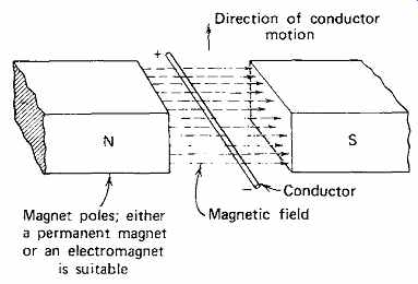
Fig. 10 The action fundamental to all generators. When a conductor of electricity
moves through a magnetic field, a volt age is induced in the conductor, with
polarity as shown.
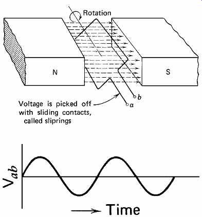
Fig. 11 Rotating a coil in a magnetic field produces an alternating sinusoidal
voltage at terminals a and b because of the alternating polarity.
EXAMPLE 4 Using the data given in Example 25.2 and Fig. 4, determine (a) the power loss in the wiring and (b) the power input to the load.
SOLUTION (a) The total power loss in the wiring is W = I 2 R = I 2
(rbc
+ rda )
= (10) 2
× 0.04 = 4 W (b)
The power taken by the load is W = I 2 R = I 2 Rcd
= (10) 2
× 1.15
= 115 W (or 0.115 kW).
Alternatively, we can find this power by multiplying voltage and current. The voltage on the load is IR = 10 × 1.15 = 11.5 V and
W = VI = 11.5 × 10 = 115 W (or 0.115 kW).
EXAMPLE 5
Refer to Fig. 7. Assume a 150-W incandescent lamp at each ceiling outlet. Also assume the load connected to one convenience outlet to be a 10-A hair dryer with a power factor of 0.80. Calculate the current and power in the two branches of the circuit, and the total circuit current, assuming a 120-V ac source.
SOLUTION
(a) In the circuit branch feeding the lamps, the power consumption is for two 150-W lamps; that is, P = 2(150) = 300 W To calculate the current, we would use Equation 7, which expresses power in an ac circuit:
W = VI × pf
Because incandescent lamps are effectively resistive loads, their power factor is 1.0. Therefore:
Power = VI 300 W = 120 V × I
I == 300 W 120 V 2.5 A (b) In the second branch, we have a 10-A, 0.8-pf load.
Power in watts = volts × amperes
× power factor
W = 120 × 10 × 0.8 = 960 W However, the branch volt-amperes are
V × A = 120 × 10 = 1200 VA This latter figure is important for sizing electrical equipment.
(c) To calculate the total current flowing from the panel to both branches of the circuit, we must combine a purely resistive current (lamp circuit) with a reactive one (dryer circuit). The exact value of the current is the vectorial sum of the two branch currents, which calculates to be 12.1 amperes. (Vectorial addition is a technique that considers the phase angle between two currents.
Phase angle, or phase difference, was noted previously.) In normal circuit design practice, the arithmetic sum of 12.5 amps would be used. The error introduced is only 3.2%, and because it results in slightly oversized circuit components, it is on the safe side. Only where power factors are very low would a designer use vectorial addition to more accurately size a circuit. ¦ One further example will demonstrate the importance of power factor in normal situations.
EXAMPLE 6
The nameplate of a single-phase motor shows the following data: 3 hp, 240 V, ac, 17 A. Assume an efficiency of 90%. Calculate the motor (and therefore circuit) power factor.
SOLUTION
The conversion 1 hp = 746 W is found. Therefore, 3 hp = 3 × 746 = 2238 W This represents the motor output. Because for any device efficiency output input
=
then power input 2238 W
0.9 2487 W ==
However, for ac, power = volts × amperes × power factor so
2487 W = 240 V × 17 A × power factor and power factor 2487 W 240 17
0.61 =
×
=
Note the large difference between volt-amperes and watts:
V × I = 240 × 17 = 4080 VA P (as before) = 2487 W where P designates power. This difference is important in circuit design, as will be seen in the discussion of methods for sizing circuit components.