Making a good die begins with the die designer. If the die is designed and made correctly, it will work properly and require infrequent, simple repairs at most. This section progresses from the basics to more advanced concepts that all diemakers and designers use frequently. Thus it serves as a source of information to solve problems for the apprentice and trainee, as well as those with decades in the trade.
Systems of Length, Area, and Force measurement
In North America, many shops still carry out engineering calculations for stampings using measurements based on the inch for length and thickness. Shear or yield strengths are based on pounds per square inch (psi). Usually, the press force in short tons is based on 2,000 lb.
The metric system is in standard use through out most of the world. Metric pressworking linear and area measurements are in terms of the meter, centimeter, and millimeter. Pressworking forces in metric tons based on 1,000 kilograms are common in Asia. However, most of the metric world uses the kilo-Newton (kN) or mega-Newton (MN). The preferred metric unit for material strength is the kilo-Pascal (kPa) or mega-Pascal (MPa).
Simple die piercing
FIG. 1 illustrates a sectional view of a simple die for piercing a hole in a part. Such dies may have several punches. In addition, a cut-off shearing operation may be included if the die is fed with strip or coil stock. On contact with the stock, the punch compresses slightly, as shown in FIG. 1b. The punch is fastened to the upper die shoe by means of a retainer with a hardened backing plate. A slug can be seen falling through the lower die shoe. On the upstroke of the press, the stock is stripped from the punch by a simple fixed or tunnel stripper.
Die-cutting operations
Cutting, which includes shearing, is one of the most common pressworking operations. A single formed stamping, such as a sieve or automobile inner door, has many holes, all of which are produced by cutting operations.
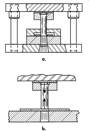
FIG. 1. (a) Sectional view of a cutting die for producing round holes; (b) the
punch is compressed after making initial contact with the stock.
Cutting operations essentially are a controlled process of plastic deformation or yielding of the material, leading to fracture. Both tensile and compressive strains are involved. Bending or distortion of the scrap metal trimmed away and metal cut out by the punch may occur. Stretching beyond the elastic limit occurs, then plastic deformation, reduction in area and, finally, fracturing starts through cleavage planes in the reduced area and becomes complete. FIG. 2 illustrates a sectional view of a successful hole cutting operation.
The cutting of metal between die components is a shearing process in which metal is stressed in shear between two cutting edges to the point of fracture, or beyond its ultimate strength.
Clearance
There are general rules governing the amount of clearance between the punch and die. The clearance amount varies as the type of material and thickness varies. Clearance normally is expressed as a percentage of stock thickness per side. Once a clearance has been determined, it is critical that it be maintained when the punch and die are made.
For mild steel, the clearance per side varies between 5-12% of stock thickness. Soft material such as aluminum, brass, and draw-quality, cold rolled steels generally run best between 9-11% per side. Low-carbon, cold-rolled and hot-rolled, pickled and oiled steels, CDA 110 copper, and hardened brass tend to run best at 12 or 13% per side. Higher-carbon steel and annealed stainless steel run best at 14% per side. Hardened materials require additional punch-to-die clearance.
Optimizing the amount of die clearance to best suit the material being cut may require some experimentation to minimize an uneven fractured edge condition. By increasing clearance, within reasonable limits, cutting force is lowered. This extends tool life and increases the number of parts produced before the tool requires sharpening. A limiting factor is burr height and taper permitted, as the size may be out of tolerance.
Insufficient Clearance
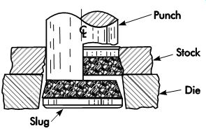
FIG. 2. Section view of a successful hole-cutting operation involving normal
clearances. Note that both the cut edge and slug have one-third of metal
thickness as a sheared edge shear and two-thirds fracture typical of common
die stamping operations.
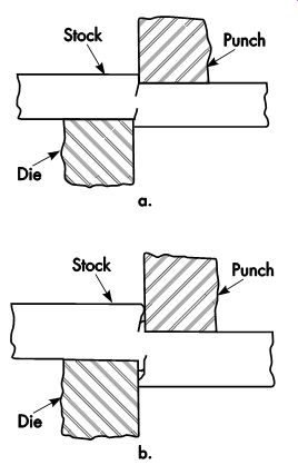
FIG. 3. (a) Cutting with insufficient clearance. (b) As fracture continues,
rough tearing occurs and the fracture paths will not meet.
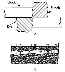
FIG. 4. (a) Insufficient clearance results in a double fracture or breakage
condition. (b) Appearance of a cut edge with a double-breakage condition.
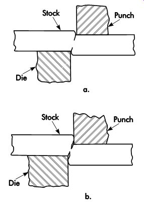
FIG. 5. (a) Start of punch penetration and fracture with a relatively large
punch-to-die clearance. (b) The fracture paths will meet evenly.
In general, tight clearances will result in holes having a high ratio of shear or burnish to fracture, and less taper at the expense of accelerated tooling wear. The fracture, which starts from each side, may not meet evenly and may leave a ragged edge, as shown in FIGs. 3 and 4. One or more sharp projections may result. Essential indicators for the diemaker are secondary shiny areas on the inside of the hole and/or slug and a rough, torn fracture. The die may burnish the torn peaks of the fracture.
Generally, tight clearances in the 3-5% per side range result in:
• parts with less taper on the cut edge;
• fewer tendencies for the slug to be pulled from the die opening;
• higher cutting forces, and
• a tendency to have double breakage problems, especially with thick materials.
As larger clearances in the 7-25% range are used, the result is often:
• longer punch and die life between resharpening;
• a need to use a means to ensure against slug pulling;
• lower cutting forces;
• avoidance of double breakage, and
• greater edge taper and more burr height.
Double-Breakage Solutions
Double breakage sometimes occurs when too little clearance is used. The solution usually requires increasing the punch-to-die clearance. Making the punch smaller is frequently the solution. This will maintain both the size of the hole and part. There will be an increase in the taper of the fracture. The cutting action is shown in FIG. 5.
Clearances of 12-15% per side may be required to eliminate double-breakage problems in soft steels.
In some thick blanks, 25% per side is occasionally necessary. The cut edges may have a pronounced taper in the fractured portion of the cut edge. Die roll and burr height also may be more pronounced.
These edge conditions, shown in FIG. 5b, may be acceptable for many applications.
If the clearance is large, higher than normal forces may be required. The hole's cut edge may have a pronounced die roll, taper, and burr height (see FIG. 6). Large clearances also result in high lateral forces on the punch and die, which can shorten tool life.
Applying Clearances to Irregularly Shaped Blanks
FIG. 7 illustrates how to apply clearances to obtain the correct sizes of holes or blanks.
When the metal punched out is the functional part, and the metal around the opening is scrap, the die is made to the desired part size and the clearance is subtracted from (applied to) the punch size as shown in FIG. 7a. Another simple example would be the outside diameter of a common flat washer. When the slug is discarded and the punched opening is functional, the required clearance is applied (added) to the die opening as shown in FIG. 7b.
Center of pressure
If the contour to be blanked is irregularly shaped, the summation of shearing forces on one side of the center of the ram may greatly exceed the forces on the other side. Such irregularity results in a bending moment in the press ram and undesirable deflections and misalignment.
For critical work, such as fine blanking, it is necessary to find a point about which the summation of shearing forces will be symmetrical.
This point is called the center of pressure, and is the center of gravity of the line that is the perimeter of the blank. Note that this is not the center of gravity of the area. The press tool is designed so that its center of pressure will be on the central axis of the press ram when the tool is mounted. If this is not possible, it may be feasible to offset the tool in the press to achieve the same goal.
The use of CAD provides many methods for locating the center of an irregular area. If it is used when designing the part, the center of pressure (not center of area) can be easily located.
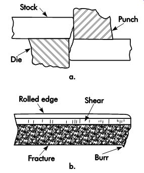
FIG. 6. (a) Completion of punch penetration and fracture with a generous
punch-to-die clearance. (b) View of a cut edge with large punch-to-die clearances.
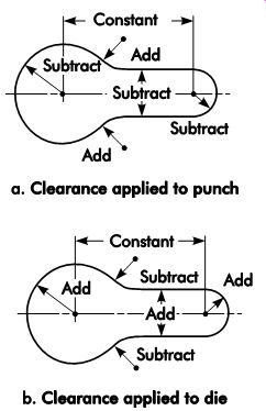
FIG. 7. How to apply clearances to irregularly shaped holes.
Mathematical Calculation
The center of pressure may be precisely deter mined by the following procedure:
1. Draw an outline of the actual cutting edges, as indicated in FIG. 8.
2. Draw axes X-X and Y-Y at right angles in a convenient position. If the figure is sym metrical about a line, let this line be one of the axes. The center of pressure will, in this case, be somewhere on the latter axis.
3. Divide the cutting edges into line elements, straight lines, arcs, etc., and number each as 1, 2, 3, etc.
4. Find the length, L1, L2, L3, etc., of these elements.
5. Find the center of gravity of these elements.
Do not confuse the center of gravity of the lines with the center of gravity of the area enclosed by the lines.
6. Find the distance, x1, of the center of gravity of the first element from the axis Y-Y, x2 of the second, etc.
7. Find the distance, x1, of the center of gravity of the first element from the axis X-X, y2 of the second, etc.
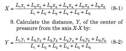
8. Calculate the distance, X, of the center of pressure, C, from the axis Y-Y by:
(1)
9. Calculate the distance, Y, of the center of pressure from the axis X-X by:
(2)
In FIG. 8, the elements are shown and numbered 1, 2, 3, etc. The length of 1 is obtained directly from the dimensions. It has a value of
4. The center of gravity is evidently at the geo metrical center of the line. Therefore:
x1
= 0 and y1
= 4.25 + 4/2
For the second element, x2 is 1.5. The value of y2 is found from:
CG = 2r/p (8-3) where:
CG = center of gravity
r = radius of the element, in. (mm)
To find the requirements for line 3 in FIG. 8, it is necessary to solve the hypotenuse of the right triangle. The requirements of the other elements are found in a similar manner. All values are entered in TBL. 1. These values then are substituted in Equations 1 and 2.
The center of pressure, C, is therefore located as indicated in FIG. 8.
It should be noted that most computer-aided design (CAD) software can determine feature characteristics of mass, weight, perimeter, and centroids, as well as rectangular and polar moments of inertia. This process can be accomplished within seconds when material density is specified.
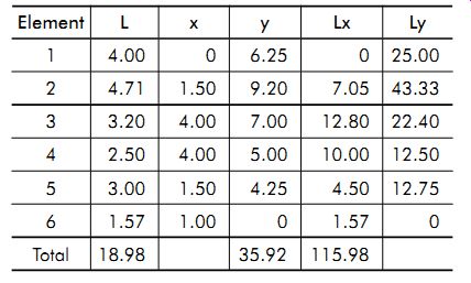
TBL. 1. Values for elements shown in FIG. 8
Wire Method of Location
The center of pressure of a blank contour may be located mathematically, but it is a tedious computation. Normally, locating the center of pressure to within .50 in. (12.7 mm) of the true mathematical location is sufficient.
One simple procedure accurate within such limits is to bend a soft wire to the blank con tour. By balancing this frame across a pencil, in two coordinates, the intersection of the two axes of balance will locate the desired point. The calculated offset should be made in the die design for critical work.
Forces
The force required to cut through stock in creases with the ultimate tensile strength of the material. Die cutting requires less energy than parting metal by tensile failure. There is no absolute relationship between tensile strength and shear strength. Typically, shear strength is 60-80% of ultimate tensile strength.
Generally, the ultimate tensile strength of the material, which is used to calculate the cutting forces based on the area of material cut, provides a substantial safety factor. For example, AISI SAE 1010 cold-rolled steel has an approximate ultimate tensile strength of 56,000 psi (386 MPa) and shear strength of 42,000 psi (290 MPa). The shear strength of the material increases due to the fast strain rates encountered in high-speed pressworking. The ultimate strength provides the safety factor in such cases.
The die designer or engineer must calculate force requirements to determine the size and type of press required. An assumption that the pressroom can somehow fit a new job into an existing press can be a foolish blunder.
The length of cut, material thickness, and shear strength are calculation entry items in CAD software. Most can automatically calculate tonnage if all of the correct data is entered.
Determining Length of Cut
To calculate the force required for cutting or shearing materials, the actual total length of cut is required. The dimensions printed on the part provide a starting point. For progressive die work, all pilot holes and work done to cut the carrier strip must be included.
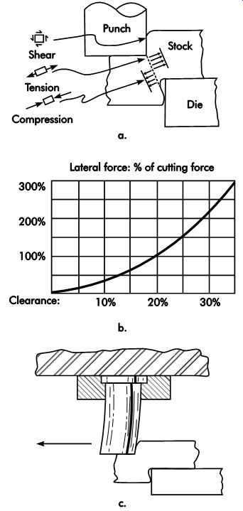
FIG. 9. (a) Shear, tensile, and compressive forces occur during the cutting
process; (b) as punch-to-die clearance increases, the lateral force, or the
side thrust, rapidly increases; (c) as side thrust increases, the cutting
clearance may increase, leading to greater side thrust or lateral forces,
and potential tool failure.
Determining Theoretical Peak Cutting Force
To determine the theoretical peak cutting force, multiply the total length of cut by the stock thickness to obtain the area of material cut. Then, multiply the total area of cut by the shear strength of the material. Equation 8-4 is useful for calculating cutting forces. Making no allowance for shear angles or timing of entry provides a safety factor.

Fs
= L × t × Ss
( 4) where:
Fs = force required to shear in the same sys tem of units as L, t, and S, lbf (kN) L = length of cut, in. (mm) t = thickness of material, in. (mm) Ss
= shear strength of the material as defined by ASTM tests
Stripping Forces
A properly designed tool needs to have a method for holding the work while the punch is pulled back through the material. This strip ping process can be by either a fixed-bridge or spring-loaded stripper. Thinner material requires a spring-loaded stripper because the material lacks the strength to prevent deformation when the punch is withdrawn from a hole.
The force required to strip the stock from a punch is difficult to determine with accuracy since it is influenced by the type of metal being cut, area of metal in contact with the punch, punch-to-die clearance, punch sharpness of the stripper spring position with respect to the punch, and numerous other factors. The following rough empirical equation is used for approximations:
F = L × T × 1.5 (8-5) where:
F = stripping force, ton L = length of cut, in.
T = material thickness, in.
When using metric units:
F × L × T × 20,600 (6)
where:
F = stripping force, kN
L = length of cut, mm
T = material thickness, mm
Press Tonnage
Press tonnage is determined by the sum of all the forces required to cut and form the part.
Practical experience with presses equipped with tonnage monitors shows close agreement between calculated versus measured values. In many cases, the stripping force must be added to the cutting force if a spring-loaded stripper is used because the springs must be compressed while cutting the material. Likewise, any spring pressure for forming, draw pads, etc., will have to be added. Using fixed (or tunnel) strippers will keep the press load to a minimum, but these devices will not control the stock as well as spring-loaded strippers.
Side-thrust or Lateral Forces
FIG. 9a illustrates the shear, tensile, and compressive forces that occur during the cutting process. The amount of lateral force varies with the cutting clearance and material.
For round and symmetrical holes, the lateral forces balance out. However, the die must be sufficiently strong to withstand high spreading forces. For notching, shearing, and other unbalanced operations, the alignment system of the die must not allow excessive deflections to occur.
Side-thrust or lateral force can result in excessive deflections of die components, such as punches, heel blocks, and guide pins. As lateral deflection occurs, clearances increase.
The lateral pressure can exceed the press force by a factor of three or more, due to a wedge-like, mechanical advantage. If not carefully controlled, the resulting misalignment can damage the tooling and produce scrap parts.
Effect of Die Clearance on Lateral Forces
Equation 7 gives an approximation of the side-thrust or lateral force generated when cut ting or shearing. When applying this equation, adjustments for the type of material and die conditions must be made. FIG. 9a shows that cutting operations involve some bending. The graph in FIG. 9b is based on Equation 7.
( 7)
where:
C = clearance, in. (mm)
FH = side thrust, lbf (kN)
T = material thickness, in. (mm)
P = penetration, typically 0.33 × T
FV = cutting force, lbf (kN)
Excessive clearances and dull die steels can result in extraordinarily large side thrusts. In severe cases, the side-thrust or lateral force can be so great that the die may shatter due to extreme pressures and interference of die components.
The function of die alignment system components, such as guide pins and heel blocks, is to limit deflections due to side thrusts to acceptable values. FIGs. 9b and c illustrate how side thrusts can cause punch deflection. Punch deflection increases the die clearance, thus leading to greater lateral forces.
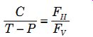
Reducing Cutting Forces
By their nature, cutting operations are characterized by high forces exerted for short periods. Sometimes it is desirable to reduce the magnitude of the force and spread it over a longer portion of the press stroke. Punch contours of large perimeter or many smaller punches frequently will result in tonnage requirements beyond the capacity of an available press. In addition, whenever abnormally high tonnage requirements are concentrated in a small area, the likelihood of design difficulties and outright tool failure increases.
Two methods generally reduce cutting forces and smooth the shock impact of heavy loads.
(Keep in mind that during a piercing operation with proper clearance, complete fracture occurs when the punch has penetrated one-third of the material's thickness.)
1. By adjusting the height of the punches so they differ in length by one-third of the material's thickness, they can cut in sequence rather than all at once. Using three punches of the same diameter and stepped properly, only one-third of the tonnage required to punch all three simultaneously is used.
2. Adding shear to the die or punch equal to one-third of the material's thickness reduces the tonnage required by 50% for the area being cut with shear applied. Note that shear should be applied to the die member (punch or die) that contacts the scrap. As a result, the deformation due to the shear angles will have little effect on the part (FIG. 10).
In piercing, the tool is designed so the direction of shear angles is generally such that the cut proceeds from the outer extremities of the contour to ward the center. This avoids stretching the material before it is cut free. Timing can be important to re duce the snap-through that can damage the press.
Limiting factors in how much timing can be used to reduce tonnage requirements include:
• the allowable tonnage as a function of the distance above the bottom of the press stroke, and
• the allowable loss of flywheel energy per stroke.
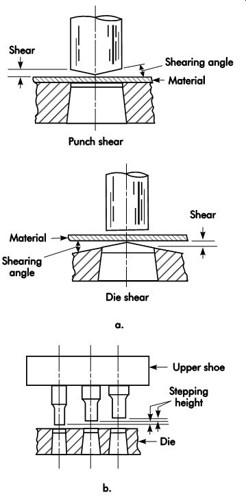
FIG. 10. Three methods to reduce cutting forces.
Analysis of Snap-through Forces
The loud boom that characterizes a snap through problem when cutting metal directly results from the sudden release of potential energy stored in press and die members as strains or deflection occur. The deflection is a normal result of the pressure required to cut through the material. In extreme cases, the energy released can damage the press. The press connection (the attachment point of the pitman to the slide) is easily damaged by the reverse load generated by snap-through. As a rule, presses are not designed to withstand reverse loading of more than 10%, and the shock may result in die components working loose.
In timing punch entry or die shear, care must be taken to provide a gradual release of developed tonnage. The shock normally is not generated by the impact of the punches on the stock. In fact, when the punches first contact the stock, the initial work is done by the kinetic energy of the slide. To complete the cut, energy must be supplied by the flywheel. As this occurs, the press members deflect. An analysis of the quantity of energy involved will show why a gradual reduction in cutting pressure before snap-through is important.
The magnitude of actual energy released increases as the square of the actual tonnage developed at the instant of final breakthrough.
The actual energy is given by:
( 8) where:
E × 166.7 = energy, ft-lbf (1 ft-lbf = 1.356 J)
F = pressure at moment of breakthrough, tons
D = amount of total deflection, in.
or
E × 9.807 = energy, J (1 J = .738 ft-lbf)
F = pressure at moment of breakthrough, metric tons (kgf × 1,000)
D = amount of total deflection, mm
For example, if 400 tons (362.8 t), which resulted in .080 in. (2.03 mm) total deflection, were required to cut through a thick steel blank, the energy released at snap-through would be 2,667 ft-lbf (3,616 J).
If careful timing of the cutting sequence results in a gradual reduction of tonnage at the instant of snap-through so that only 200 tons (181.4 t) are released, the reduction in shock and noise is dramatic. Half the tonnage would produce half as much deflection, or .04 in. (1.0 mm). The resultant snap-through energy is only 667 ft-lbf (904 J), or one-fourth of the former value.
Example: snap-through reduction by die timing. FIG. 11 illustrates a waveform resulting from an operation to punch two 1.625-in. (41.28-mm) holes and parting a chain side bar from fine-grained AISI-SAE 1039 steel. The steel was .50 in. (12.7 mm) thick by 3.00 in. (76.2 mm) wide. A 300-ton (2.7-N) straight-side press was used for this operation. The allowable reverse load is 30 tons (267 kN). Point A on FIG. 11 illustrates a peak load of 191 tons (1.7 N), which was also displayed on the tonnage meter. This is well within press capacity. In this case, the reverse load, B, was 87 tons (774 kN), which is nearly three times the allowable amount. The die was immediately taken to the repair bench and one punch was shortened .312 in. (7.92 mm). FIG. 12 illustrates the improvement achieved by modifying the tool. The peak tonnage was reduced to 82.8 tons (737 kN), which is less than half the initial value. The reverse load was reduced to 22 tons (196 kN), or about one-fourth of the former value. This is keeping with the square law formula for the energy suddenly released.
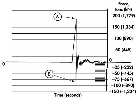
FIG. 11. Actual waveform signature of a combined piercing and cut-off operation
having excessive snap-through or reverse load.

FIG. 12. Waveform signature after adding timing and balanced shear.
Ball-Lock punches
The ball-lock concept of retention and quick punch replacement has been in use for many years. Style changes on a stamping can be made quickly, without removing the die from the press, simply by pulling or adding punches. In the event that a fragile punch needs replacement during the run, the ball-lock system of punch retention makes this operation quick and easy. FIG. 13 illustrates the ball-lock retention system used to positively lock both a punch and die button (matrix) in a die. The ball-lock retention is an adaptation of the wedge principle. Once correctly seated, the ball locks the punch in position both vertically and radially, while permitting rapid replacement of the punches in the die assembly.
To install a ball-lock punch, it is inserted into the retainer and twisted until the spring-loaded ball drops into position, locking the punch. The punch is removed by depressing the ball with a ball-release tool inserted into the hole in the retainer provided for this purpose. This action frees the punch so it can be pulled out of the retainer.
Some retainers use a ball-release screw, as illustrated in FIG. 13. To ensure correct location and certain retention, it is important that the ball-locking condition be correct. There can be a problem if the ball is either too low or high in the teardrop-shaped ball seat. This problem can be avoided by always using the correct retainer specified for a given punch and the proper size replacement ball, as shown in FIG. 14.
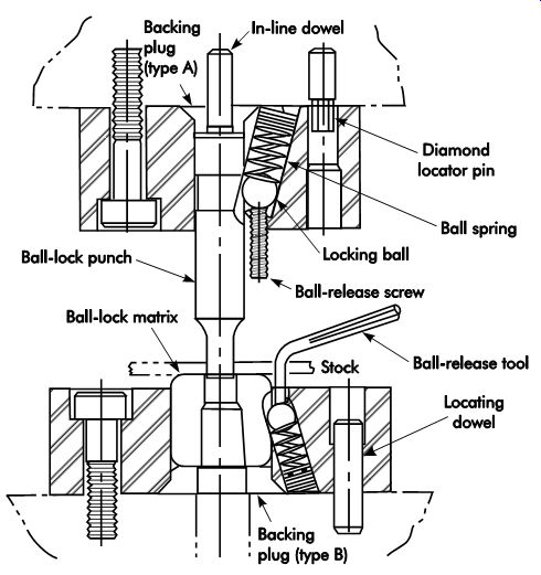
FIG. 13. The ball-lock retention system used to positively lock both a punch
and die button (matrix) while permit ting rapid replacement of these components
in the die assembly.
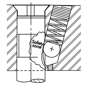
FIG. 14. The ball must be properly seated in the teardrop-shaped pocket
in the punch.
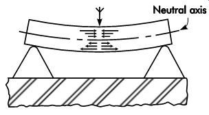
FIG. 15. A metal beam supported at two points, with a load applied at the
midpoint, resulting in bending or deflection.
Bending
Bending frequently is used to increase the rigidity of shaped parts in pressworking operations. The simplest bending operation is air bending, so called because the die does not touch the outside of the bend radius. The part to be bent is supported on each side of the bend and force is applied to a forming punch in the center.
FIG. 15 illustrates a metal beam supported at two points, with a load applied at the midpoint.
The load produces compressive stresses in the material on the inside of the bend (above the neutral axis) as it is forced into compression. Tensile stress or stretching occurs on the outside of the bend (below the neutral axis). To produce a bend in a finished part, the yield point of the material must be exceeded. If the bending force applied does not exceed the yield strength of the material, the beam will return to its original shape on removal of the load, as shown in FIG. 16. However, if the stress exceeds the material's yield strength, the beam will retain a permanent set or bend when the load is removed, as illustrated in FIG. 17.
The goal of the process is to bend the material the correct amount. Springback, or elastic recovery, will occur until residual stresses in the bend are equal to the stiffness of the material. This concept is illustrated in FIG. 18.
Not all of the material in the bend zone is stressed equally. The material in the inner and outer surfaces is stressed the most, and the stress gradually diminishes toward a neutral axis be tween the two surfaces. At that point, the stress is zero and there is no length change.
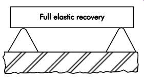
FIG. 16. If the applied force does not exceed the material's yield strength,
the beam returns to its undeflected shape.
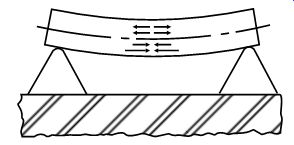
FIG. 17. Simple beam deflection occurs in air bending. If the applied force
exceeds the material's yield strength, the beam retains a permanent set or
bend when the load is removed.
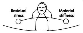
FIG. 18. Springback occurs until the residual stress forces are balanced
by the stiffness of the material.
Bend Allowances
The exact length of a bend is determined by trial and error. The assumed neutral axis varies depending on the bending method used, location in the bend, and type of stock to be bent.
The direction of grain in a steel strip relative to the bend radius has a slight effect on the length of metal required to make a bend. Bending with the grain allows the metal to stretch more easily than bending against the grain. However, this results in a weaker stamping.
Bend allowances depend on the physical properties of the metal, such as its tensile and yield strength and ductility.
The exact bend allowance is the arc length of the true-neutral axis of the bend (metal is stretched above the neutral axis; below it, metal is compressed). The neutral axis only can be approximated. Many manufacturers assume the neutral axis is 1/3-stock thickness from the inside radius of the bend for inside radii of less than twice the stock thickness. For an inside radii of two times the stock thickness or greater, the neutral axis is assumed to be 1/2-stock thickness from the inside radii. One reason for the requirement of relatively less metal to make a tight bend is that the sharp radius tends to be drawn or stretched slightly.
Many experts believe that the location of the true-neutral axis from the inside radius varies from 0.2-0.5 times the stock thickness. An important factor that determines the neutral axis is how the bend is accomplished. Less metal is required for a bend made by a tightly wiped flange than for an air bend on a press brake. Wiping the flange tends to stretch the metal.
Equations
For 90° bends, the coefficient of 1.57 (the number of radians in 90°) determines the assumed amount of metal necessary to make a bend, which is multiplied by the assumed neutral axis. For bends that are not exactly 90°, it is necessary to multiply the number of degrees of bend by 0.0175 (the number of radians in 1°), and to substitute the result for the coefficient 1.57. The actual neutral axis will vary from the stock centerline to 20% from the inside of the bend for sharp bends.
Springback or elastic recovery
Stiffness is a function of the material's modulus of elasticity. This explains why some materials, such as mild steel with a high modulus of elasticity (as compared to tensile strength), spring back less than materials with a lower modulus. How ever, some materials do have comparable tensile strength, such as hard aluminum alloys.
Some springback occurs whenever metals are formed. Springback is caused by the residual stress that is a result of cold-working metals. For example, in a simple bend, residual compressive stress remains on the inside of the bend, while residual tensile stress is present on the outside radius of the bend. When bending pressure is re leased, metal springs back until residual-stress forces are balanced by the material's stiffness, which resists further strain. The most common method used to compensate for springback is overbending, in which material is bent a sufficient amount beyond the desired angle and allowed to spring back to the desired angle after elastic recovery occurs. Because of the uncertainty of the exact location of the neutral axis, it is best to use trial-and-error methods when developing close-tolerance stampings.
Many complex factors determine the amount of springback that will occur in a given operation. Because the exact amount of springback is difficult to predict, data for a specific material and forming method is often developed under actual production conditions to aid process control and future product development. If the die designer and builder fail to include correct springback compensation in the die, correction will need to be done by the repair facility of the press shop that uses the tool.
Factors Affecting Springback
Some factors that increase springback are:
• higher material strength;
• thinner material;
• lower modulus of elasticity;
• larger die radius;
• greater wipe-steel clearance;
• less irregularity in part outline, and
• flatter surface contour of the part.
If a flanged part is irregular compared with either the outline or surface contour, the spring back will be slight. The springback for large wipe steel clearances can be several degrees or more.
Air Bending
Press-brake tooling for air bending (FIG. 19) is quite simple. Air bending is one of the most common press-brake operations. It requires minimum tonnage for the work performed. Exact repeatability of ram travel is required to maintain close repeatability of the bend angle. The amount of over-travel is determined experimentally to compensate for springback.
causes of Bend-angle Variation There are several causes of bend-angle variation when bending materials in pressworking operations. These include:
• changes in stock yield strength;
• variation in stock thickness;
• machine variations due to temperate changes; and
• machine deflection, especially in long press brake-bending operations.
Compensation for change of any condition that affects the bend angle may require adjustment of the ram travel. With press-brake-bed deflection, shimming also may be required. In addition, shims may be required to correct for additional machine deflection. Some press-brake designs have automatic deflection-compensating devices, such as hydraulic cylinders built into the bed. If high force is required in press-brake bending because of an increase in stock thickness or hardness, a simple ram adjustment may not be enough to correct the problem.
Coining
Coining, or bottom bending, has the advantage of producing sharp, accurate bends with less sensitivity to material conditions than air bending. The disadvantages of coining compared to air bending are high force requirements and accelerated die wear.
FIG. 20 illustrates a press-brake die de signed to coin the bend for a precise angle. This coining action eliminates the root causes of springback, including the tensile and compressive residual stresses on opposite sides of the bend. Coining action is accomplished with pres sure sufficient to subject the metal to the yield point in the bend area.
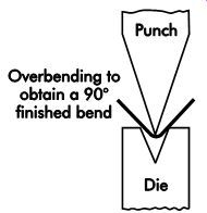
FIG. 19. Simple tooling of the type used to air bend sheet-metal parts in
press brakes. The upper die is lowered a little and a hit is made until the
desired bend angle is obtained.
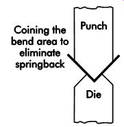
FIG. 20. Coining the bend requires high tonnage to obtain a sharp, accurate
bend.
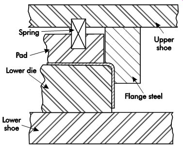
FIG. 21. Sectional view of a wipe-flanging die.
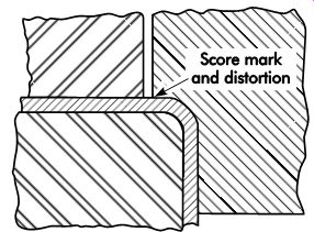
FIG. 22. Close-up view of the point of flange steel contact on the bend
radius in a wipe-flanging die.
The tonnage required for coining might be five to 10 times that required for simple air bending. Higher forces increase machine deflection.
Air-bending jobs that produce acceptable bend angles throughout the entire length of the bend may need shimming if coining is required. The amount of machine deflection increases approximately in proportion to the developed tonnage.
Wipe Bending
It is often not feasible to use V-bending tooling for bending. V-bending is popular for press-brake work. The tooling is simple and can accomplish a variety of work. Usually, only a single bend occurs per stroke. Accurate work requires that each previous step be accurate. Skilled and experienced operators are required. A limiting factor is the cost of press-brake work, because of low throughput and the high skill required for accuracy.
Wipe Flanging and Springback Control
FIG. 21 illustrates a sectional view through a wipe-flanging die. In this design, the flange steel attached to the upper die wipes the metal around the lower die. A popular method for controlling springback is to coin the top of the bend with the flange steel. A disadvantage is the limited spring back compensation that can result in a distorted bend-angle condition. A close-up view of this is shown in FIG. 22. The top thickness of the bend can be squeezed beyond the material's yield point by careful adjustment of the die's shut height. Only the top portion of the bend is coined. This can result in a score mark that might weaken the stamping and extrusion of the metal being coined.
If excessive coining pressures are applied, the metal at the top of the bend will extrude and result in a weak and distorted bend condition. An improved flanging method relieves the radius in flange steel so it does not contact the top of the bend radius. One way to do this is to relieve the flange steel at an angle approximately 20° tangent to the radius. Another method is to machine the flange steel to a radius that is larger than the out side of the bend. The flange steel is positioned so the tightest point is 45-60° beyond the top of the radius. The side of the form steel is relieved 5° or more to permit the material to be overbent (FIG. 23). This method is more effective than coining the top of the bend. In addition, the improved bending process is not as sensitive to variation from press adjustments and material conditions.
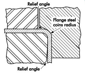
FIG. 23. The side of the radius is coined and a relief angle is provided
in the lower die steel in this improved springback control method.
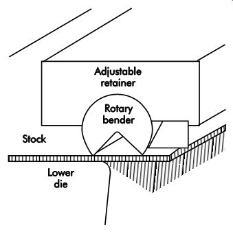
FIG. 24. A Ready bender makes initial contact with the stock. As the die
closes, the bender clamps and bends the stock.
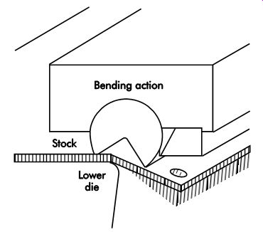
FIG. 25. A Ready bender bends the stock through rotary action of the circular
member.
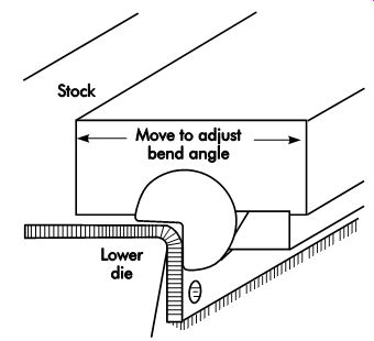
FIG. 26. A Ready bender overbends the stock at the bottom of the stroke
to provide for springback.
Rotary-action die Bending
A patented rotary-action bender known as the Ready™ bender combines the low tonnage requirements of air bending with the accuracy and multiple-bend capabilities of wipe-flange tooling. FIG. 24 illustrates a Ready bender making initial contact with the stock. As the up per die travels down, the stock is clamped and bent by the rotating bender. As the die closes, the rotary-bending action progresses (FIG. 25). An optional relief angle in the lower die permits the rotary member to overbend the stock at the bottom of the stroke to provide springback control (FIG. 26).
Rotary-action benders can bend angles up to 120°. The rotary member usually is made of heat-treated tool steel for long wear. The bending pressure is typically 50-80% less than that required for conventional wipe bending. The lower pressure permits many types of pre-painted materials to be fabricated without damaging the finish. Rotary benders also can be constructed of nonmetallic materials, such as hard thermoplastics, for work with prefinished materials.
Fine Adjustment of Bend Angle
On conventional wipe-flange tooling, bend-angle adjustment is usually made by adjusting the flange steel up or down with shimming. In the case of rotary-action benders, the bend angle is adjusted by moving the assembly containing the bender along the horizontal plane relative to the lower-die member or anvil. Attempts to obtain a tighter bend by excessive lowering of the press shut-height can result in tooling damage.
Forming
A large percentage of stampings used in the manufacturing of products require some forming operations. Some are simple forms that require tools of low cost and conventional design. Others may have complicated forms, which require dies that produce multiple forms in one stroke of the press. Some stampings may require several dies to produce the shapes and forms required.
Forming dies, often considered in the same class with bending, are tools that form or bend the blank along a curved, instead of straight, axis.
There is little stretching or compressing of the material. The internal movement or plastic flow of the material is localized and has little or no effect on the total area or thickness of material.
A first consideration in analyzing a stamping is to select the class of die to perform the work. Next, determine the number of stampings required, which will help identify the forming process to be used.
A forming die may be designed in many ways and produce the same results. The tool that is cheapest and has the simplest design may not always be best because it may not produce the stamping to the drawing specifications. Where limited production is required, press-brake tooling often can be used.
Solid forming dies
The solid forming die is of simple construction and design. A forming die of this kind need not be mounted on a die set as shown in FIG. 27. A die set can be considered because the repeatability of the setup reduces the chances for misalignment. A great deal of side pressure is exerted on the female die block, which must be considered in the design.
One option is to make the female block out of two pieces of tool steel held together by pre stressed tie rods. This is used as a safety measure in case the operator should feed a double blank or if metal of a thicker gage is used. The use of a computer-aided stress analysis program is advised to determine the areas of high tensile stress so the die blocks can be proportioned accordingly.
In some cases, a relief under the center of the female die will transfer much of the tensile strain to the more robust bottom of the female die-this is the same mechanical principle as a bridge with truss work under the roadway. Operating dies of this type in a hydraulic press is advised to limit the pressure applied to the die, especially if coining pressures are achieved.
Coining dies
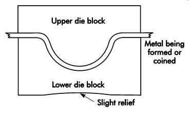
FIG. 27. A set of forming blocks used without a die set.
Coining dies are useful for achieving precise forms by coining-a process for bringing the entire thickness of the metal up to the yield strength of the material. Applications for coining may include sizing bearing shell halves, but any curved stamping requiring accurate form dimensions is a candidate for coining.
Flat coining often is done to produce parts with high flatness requirements. Another application for flat coining blocks is the production of medal lions of materials varying from stainless steels to sterling silver and gold alloys. Surprisingly high forces are required to bring up all of the detail in some medallion work. Forces of 325 ksi (2,240 MPa) or higher are achieved.
Forming die design
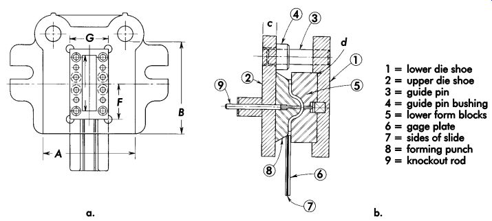
FIG. 28. Pressure-pad-type form dies.
FIG. 28 is an example of a two-piece forming die mounted in a die set and equipped with a positive knockout. A close-fitting cutout is machined into the lower die shoe to limit shifting of the lower form detail. The form blocks are made wider than the workpiece and their height by an approximate ratio of 1:1.5. The radius being formed should be at least twice the metal thickness to avoid excessive stress concentration. A good polish on the form blocks will ensure against marring the stamping.
The punch is made of a good grade of tool steel, which is heat-treated for toughness. Grade S5 or S7 are good choices for severe work.
Consideration is given to stripping the formed part from the punch. This is accomplished by means of a knockout rod application, stripper hooks, or stripper-pin (spring) construction. It is important to consider and plan for removing the formed part. FIG. 28b shows these details and illustrates the gages necessary for locating the stamping.
The shoe is thick enough to withstand the pressure required for the forming operation. In selecting its thickness, the size, shape of the bolster, and plate of the press are considered. The A and B dimensions of the shoe, when placed over the hole of the bolster plate, should be long and wide enough to allow ample space for clamping it to the bolster plate. A die shoe made of steel will give good service and costs only a little more than cast iron. Select the diameter of the guide pins according to the working area of the shoe, or by consulting a die set manufacturer's catalog. The length of the pins should be at least .25 in. (6.4 mm) shorter than the shut height of the die, as listed on the drawing. The guide bushings may be of the shoulder type. Ball-bearing pins and bushings can be used if better accuracy and longer life than plain bushings are desired.
The upper die shoe is made to the same outer dimensions as the lower shoe. If a shank is to be used, Occupational Safety and Health Administration (OSHA) rules require toe clamps or some other means other than the shank alone to retain the die in the press.
Locate the screw and dowel holes so they will not mar the stamping. Dowel pins should be large enough in diameter to ensure correct alignment of the sections. The screws should be large enough to clamp the die-steel details to the shoes by friction. The screw- and dowel-hole locations also should locate the gage plate. Designing the gage-plate shape when designing the die blocks and then placing the screw and dowel holes accordingly accomplishes a dual purpose. It helps eliminate some of the holes required in the die blocks, as well as the work of drilling and tapping the holes and the cost of the extra screws. The blank should be fed the long way to ensure easy loading and accurate location. When blanks are fed the short way, they have a chance to twist, and the operator loses control over them. This causes a loss of time in locating the blank in the die, and can cause mis-location of the blank.
Make the gage plate so the blank will slide into the proper location for forming. When the blanks are wide and flat, provide ribs or wires to help slide the blank into the die and reduce some of the friction caused by the oil on the blank's surfaces. Design the slide long enough to prevent the operator from placing his or her fingers under the punch.
Pressure Pads
When the forming of stampings requires accuracy, dies employing pressure pads often are designed. A pressure pad helps hold the stock securely during forming and eliminates shifting of the blank. The pressure can be applied to the pad by springs or the use of an air cushion or nitrogen springs. When springs are used, they can be located directly under the pad and confined in the die shoe. They also may be located in or under the bolster plate of the press. By the use of pressure pins, which are located under the pad, and through the die shoe, pressure is applied to the pressure plate.
Pressure pins also are used with an air cushion. The construction of the pressure plate and pressure pins would be the same, except that an air cushion is substituted for the springs. When an air cushion is used, the proper amount of pressure on the pressure pad is ensured as long as the air supply is set properly. It is important that the die-setter use the correct pressure in the die setup procedure, as well as proper pin placement. A consistent pressure ensures repeatable stamping quality.
When springs are used to apply pressure to a pressure pad, spring pressure increases with the pad travel. Each fraction of an inch or millimeter of travel increases the pressure on the pad. This may cause some trouble when stamping light gage material because too much pressure may cause the metal to stretch. Care must be used to not over-compress the springs used, which can lead to loss of pressure and spring break age. Increasingly, nitrogen manifold systems or self-contained nitrogen cylinders are used as pad pressure sources.
The pressure pad is controlled in its travel be tween die blocks by retaining ledges or shoulder screws. When using the retaining ledge construction, a recess is machined into the form blocks and a corresponding shoulder is machined on the pad. The ledge shoulder should always be made strong enough to withstand the pressure applied by either springs or an air cushion. The size of the shoulder to be used varies according to the size and metal thickness of the stamping.
A good rule is to have the height of the ledge 1.5 times the width, as shown in FIG. 29. Always design pad ledges with a radius in the corner.
When using shoulder screws to control the travel of the pad, the die shoe must be thick enough to permit sufficient travel.
The pressure pad should always travel so that it extends slightly above the die blocks.
This will ensure uniform parts because pres sure locks the part between the punch and pad faces before the actual forming takes place.
The amount of travel in the pad depends on the height of the form die. It is not always necessary to travel the full height; in many cases, half of the die's form height is sufficient. For accurate work, allow the punch to give the part a definite set at the bottom of the stroke. When a stamping must have sides square with the bottom after forming, the corner radius should be set.
This is done by designing the die blocks with the correct radius, A, shown in FIG. 30. The pres sure pad is made to match the height of the die block's radius edge. The punch radius, C, is made slightly smaller, approximately 10% less than the die-block radius.
It may be necessary to machine a slight relief angle on the side of the punch to allow slight over bending of the side being formed. This ensures that the sides of the formed part will be square with the base after forming.
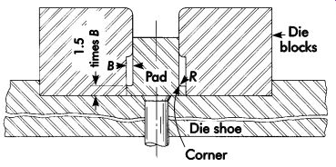
FIG. 29. Pressure-pad design.
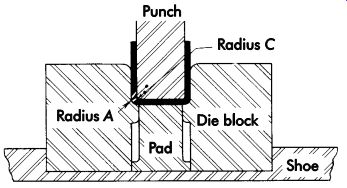
FIG. 30. Radii considerations for forming die design.
Rubber and Polyurethane
Often, a rubber or polyurethane forming die is used in press-brake operations, as illustrated in FIG. 31. This reduces tooling costs, as only the male forming punch has to be made.
This method is well adapted to forming angles channels, and radii. Another advantage is that the rubber die leaves no visible marks on the part, which is especially important when bending prefinished material.

FIG. 31. Rubber or polyurethane forming die and punches.
Embossing
In an embossing operation, a shallow surface detail is formed by displacing metal between two opposing mated tool surfaces. One surface has the depression, the other the projection. The metal is stretched slightly, rather than being compressed.
Embossing is used for various purposes, the most common being the stiffening of the bottom of a pan or container. The embossing is designed to follow the outside profile of the part. A round canister may have an embossed circle or raised grooves of various widths or panels. When a can or box is square or rectangular, embossments follow the contours. Embossments often are ribs or crosses stamped in the metal to help make a section of a blank stronger by stiffening. An embossing die can be a male and female set of lettering dies or a profile of one of various shapes.
The construction of die blocks for an embossing operation depends on the size and shape of the form, and the accuracy and flatness required. When embossing simple shapes, such as stiffening ribs, it is not necessary to strike the bottom of the relief.
The metal stretches over the punch and across the two radius edges of the die's clearance.
The female die opening has the same width of the rib or embossing punch, and a slight radius is added to the edges of the opening to allow metal to flow freely. The punch is made slightly smaller than the required metal thickness per side so that it does not strike along this area. By avoiding coining or hard marks, the pressure required to stamp the embossing is reduced and die wear is much less.
A small embossment often is used as a spot weld projection nib. Spot-welding is a process where metal is electrically welded together under controlled pressure and current. These nibs are helpful to ensure highly uniform current flow and sound spot-welds.
Beading and Curling
In beading and curling operations, the edges of the metal are formed into a roll or curl. This is done to strengthen the part or to produce a better looking product with a protective edge. Curls are used in the manufacturing of hinges, pots, pans, and other items. The size of the curl should be governed by the thickness of the metal; it should have a radius of at least twice the metal's thickness. To make good curls and beads, the material must be ductile; otherwise, it will not roll and will cause flaws in the metal. If the metal is too hard, the curls will become flat instead of round. If possible, the burr edge of the blank should be the inside edge of the curl. This location facilitates metal flow and helps keep the die radius from wearing or galling. In making curls and beads, a starting radius is always helpful. A starting radius is shown in FIG. 32.
The curling radius of the die always must be smoothly polished and free of tool marks. Any groove or roughness will tend to back up the metal while it is rolling and cause defective curls.
The inside surface of the blank must be held positively in line with the inside curling radius of the punch (FIG. 33).
When curling or beading pots, pans, cans, or pails, wires may be rolled inside the curls. This will make them stronger. The wire is made to the contour of the pan and placed on a spring pad.
When the curling die closes, the edge of the pan is forced to curl around the wire, as shown in FIG. 34. If the wire is omitted, the tooling is much the same, except the curled edge is termed a false wire curl.
Twisters and Benders
The successful manufacturing of fans requires uniform blades formed alike and of equal weight.
A hub spider must provide a precise location for the blade attachment holes in relationship to the hub shaft insert. Steel sheeting, by the very nature of the rolling process, cannot be made with out slight variations in the way it bends with and across the rolling direction or grain of the sheet.
Since the spider has a critical role in the balance and overall performance of the assembled fan, it must be made with precise bend angles in spite of the variation across the steel sheet and even larger differences from coil to coil. An example of a hub spider press is shown in FIG. 35.
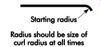
FIG. 32. Starting curl radius.
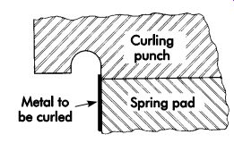
FIG. 33. Curling punch design.
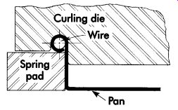
FIG. 34. Curling die design.
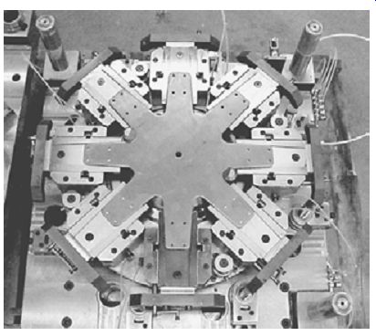
FIG. 35. Plan view of lower die with fan hub to be formed in place. Note
the two locating pins that hold the part on location. Each of the spider
legs rest on one-half of a cam-actuated bending device.
Rotary Bender operation
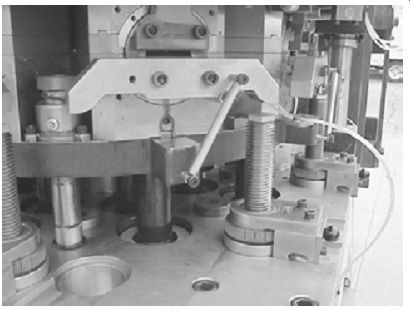
FIG. 36. A view of an individual spider bending station. The die is on the
bench and held partly open by eight self-contained nitrogen cylinders. (Modern
Die Systems, Inc.)
When the die closes with the flat spider in place (FIG. 36), the rotary motion of the lower and upper die begins forming. All eight of the forming stations ride on a circular plate supported by eight nitrogen cylinders and guided by four guide pins and bushings. FIG. 36 is a view of an individual spider bending station. As the die closes, the cam lever arm contacts the fine adjustment screw resulting in the rotary motion of the lower and upper die halves.
The die is operated in a hydraulic press, ensuring smooth, controlled closing. As the die closes, the plate, floating on nitrogen cylinders, descends until the lever arms meet the round contact pads on each adjustment screw. Thus, the adjustment of each screw controls the angle to which each corresponding spider leg is bent. The amount of adjustment needed for variations in material is determined by a gaging station, which feeds the output of precision dial indicators to a computer.
The computer provides a statistical process control (SPC) record and tells the operator how much adjustment is required to stay in the middle of the upper and lower statistical process control (SPC) limits.
Once a computer interface has been attached, it can be used to measure parts and adjust the tool during production using servomotors to ad just the screws. One such computerized gage with .00005-in. (1.3-um) resolution digital indicators can measure the angles of each spider leg to five decimal places faster than the operator can load and cycle the next part. This makes 100% inspection possible. The computer interface for the gage and die displays X-bar charts of the angle data for true "real-time" quality control. Thus quality discrepancies can be dealt with quickly.
Hole flanging or extruding
Hole flanging or extruding is the forming or stretching of a flange around a hole in sheet metal. The shape of the flange can vary according to part requirements. Flanges are made as countersunk, burred, or dimpled holes.
When countersunk, shaped, extruded holes are made in steel, it is necessary to coin the metal around the upper face and beveled sides to set the material. The holes also are made about .005 in. (0.13 mm) deeper than the required height of the rivet or screw head to allow for metal compression, which occurs when squeezing the rivet in place. A section of a die for this purpose is shown in FIG. 37. The hole can be pierced before it is placed in the countersinking die, or it can be formed and pierced in a single operation, depending on the required size.
As shown in FIG. 37, the sheet is placed over the pilot diameter, A, which locates it centrally in the die. The die body, 1, descends and forces the metal down around the flange surface of the punch. Spring pressure strips the part from the punch and releases the formed part from the die.
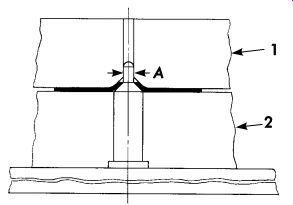
FIG. 37. A forming die used to produce countersunk holes.
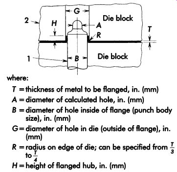
FIG. 38. A die for punching and countersinking a hole.
FIG. 38 shows a two-step punch. A hole, 1, is punched in the part and metal is forced around to the countersunk shape of the die block, 2. A hole punched by this method is always somewhat smaller than the size of the hole in the finished part. Spring pressure is used to strip the finished part from the punch. A shedder pin should be provided in the piercing point of the punch to remove the slug.
Although FIGs. 37 and 8-38 show counter sunk holes formed from the bottom up, the holes can be just as easily formed from the top down, depending on the part's design requirements.
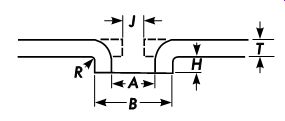
FIG. 39. Hole flange design.
90° hole flanging
The size of the pierced hole for a 90° hole flange can be calculated, but should never be used until it has been proven correct by using the same tools that will be employed in the die. To calculate the hole size, the same principles are employed as when finding a 90° bend.
When flanges are stretched more than 2-1/2 times the metal thickness in height, the wall can split. This can be prevented to some extent by burring the edge around the hole before the extruding operation. In this situation, the side of the hole with the burr is important. Coining the hole's edge is a good way to strengthen it for flanging. This is an especially attractive option in progressive die operations.
Forming a flange around a previously pierced hole at a bend angle of 90° (the most common operation) is nothing more than the formation of a stretch flange at that angle.
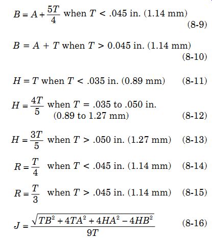
One manufacturer offers standardized flange widths (FIG. 39, dimension H) and starting hole diameters (FIG. 39, dimension J) for holes that are to be threaded. Using taps that form the metal by displacement rather than cutting the threads will result in a much stronger female thread. Following are the equations for low-carbon steel stamping stock:
when T < .045 in. (1.14 mm)
where:
B = diameter of hole inside of flange (punch body size), in. (mm)
A = diameter of calculated hole, in. (mm)
T = thickness of metal to be flanged, in. (mm)
H = height of flanged hub, in. (mm)
R = radius on edge of die, which can be specified,
J = starting hole diameter, in. (mm)
The radius, P, on the nose of the punch should be blended into the body diameter, eliminating any sharpness that could cause the metal to score as it passes over it. The radius on the body, B, or hole-sizing portion of the punch, must be as large as possible and smooth. The portion between the A and B diameters of the punch should have a radius, C, as large as possible (FIG. 40a). When using the single-station method (FIG. 40b), controlling the length of the flange is more difficult (FIG. 39, H).
Compound dies
A compound die usually refers to a one-station die designed around a common vertical centerline where two or more operations are completed during a single press stroke. Usually, only cutting operations are done, such as combined blanking and piercing.
A common characteristic of compound die design is inverted construction, with the blanking die on the upper die shoe and the blanking punch on the lower die shoe. The pierced slugs fall out through the lower die shoe. The part or finished blank is retained in the female die, which is mounted on the upper shoe.
Compound Blank and Piercing Dies
Compound dies are widely used to produce pierced blanks to close dimensional and flatness tolerances. Generally, the sheet material is lifted off the blanking punch by a spring-actuated strip per, which may be provided with guides to feed the material. If hand-fed, a stop is provided to position the strip for the next stroke.
The blank normally remains in the upper die, and is usually removed by a positive knockout at the top of the press stroke. Ejection of the blank from the die by spring-loaded or positive knock out occurs at the top of the stroke. Because of this feature, the die does not require angular die clearance. Not providing angular die clearance simplifies die construction and ensures constant blank size throughout the life of the die.
A compound die for making a washer is shown in FIG. 41. The center hole is cut and outer diameter trimmed in a single die station in one press stroke. The material is .015-in. (0.38-mm) cold-rolled steel strip. A piercing punch is attached to an upper die shoe. The blanking punch is attached to a lower die shoe. In this design, the piercing punch contacts the material slightly ahead of the blanking die. The part is stripped from both the blanking die and piercing punch by a positive knockout. The blanked strip is lifted off the blanking punch by a spring-loaded pressure pad.
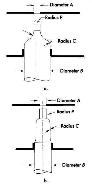
FIG. 40. (a) Two-station and (b) single-station flanging punch design.
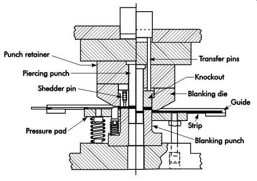
FIG. 41. A compound blanking and piercing die used to produce a washer.
Dies of this type are widely used to produce accurate flat blanks.
Part removal
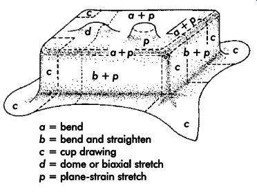
FIG. 42. A complex stamping is produced by a variety of forming operations,
each of which may be analyzed separately.
A potential disadvantage of compound dies is that the part must be removed from the upper die at the top of each stroke. The part usually is knocked out at the top of the stroke by means of a press-actuated knockout bar.
In the case of small parts, once knocked out of the upper die, they may be ejected by a timed blast of air. Larger parts can be removed by means of a shuttle unloader that enters the die opening as the ram ascends. The press ram normally drives the unloader; although air, hydraulic, or servomotor-driven units may be used.
Accomplishing part removal during each press stroke may limit the speed of the operation. For low-volume production jobs, manual removal with appropriate safeguarding precautions may suffice.
Stamping Analysis
Forming flat sheet metal into complex, radically deformed stampings may appear to involve skills and processes that are more art than science.
Modern stamping design and development techniques permit the product designer to work with manufacturing and tooling engineers to design parts that can be manufactured with certainty. A complex stamping is shown in FIG. 42.
Stamping designs should be based on the data of successful prior designs and analytical form ability methods. Uncertainty concerning the manufacturability of complex stampings often results in added expense and delays, such as:
• trial production on temporary tooling to prove process feasibility;
• delays in marketing the product while the process or product design is changed;
• specifying more operations than needed as a safety factor; and
• choosing alternative processes and materials such as molded plastics.
Computerized techniques
Simple computer software programs are avail able to ensure that proposed stamping designs can be manufactured with certainty. Using these programs avoids costly trial-and-error guess work. Software is available to analyze the amount and type of deformation in a stamping design.
Computer-aided analysis ties in nicely with computer-aided design (CAD) design of stampings. The analysis should be applied early in the product design process. The CAD math data, which describes the part, is used for computerized formability analysis. Computerized analysis falls into several categories, such as:
• simple sectional analysis programs;
• general analysis programs that fully model the part, which are typically based on finite element analysis; and
• programs that analyze the stamping based on the type of deformation occurring in an individual area.
Sectional Analysis Programs
Sectional analysis is good for identifying and troubleshooting a number of simple forming conditions. Computer programs are useful for determining the amount of strain present in a specific area of a stamping so that anticipated design problems can be checked easily.
A moderately priced personal computer has sufficient computational capacity to run sectional analysis programs to determine strain conditions.
Estimating the effect of surface friction on metal movement is a useful feature of nearly all computerized formability analysis programs.
General Analysis Programs
General analysis programs are required to completely model a part using the finite-element or finite-difference methods. Stamping the whole part is simulated in three dimensions with a single computer program. Many complex inter actions occur during the stamping simulation.
General analysis programs require the calculation and interaction of many complex variables occurring throughout the forming process.
Simplifying Analysis
A simplified approach breaks down complete stampings into local regions for individual analysis. Following this approach, a stamping is analyzed as individual zones that interact in a predictable manner as they are formed. Some good programs include an expert systems approach based on a library of successful designs.
Circle Grid Analysis
Circle grid analysis (CGA) is a powerful process control tool. Data on essential areas of the stamping near the forming limit should be checked periodically to determine the effect of die wear on formability. Should a production stamping process start to experience problems, a blank of the material can be quickly gridded and analyzed. The CGA results can be compared with historical data for the part and steel formability specifications.
Measuring Deformation
The CGA technique permits measurement of the deformation that occurs when forming stampings. First, a grid is stenciled on the surface of the blank by dye transfer or electrochemical etching.
This grid deforms with the blank and allows ac curate calculations of the strain or deformation that occurred during the stamping operation.
Press Shop Applications
If a part always runs well within the safety zone, often a less costly steel or lubricant can be used. If only a few areas on the stamping are close to failure, a blank-holder improvement or minor product change often will ensure manufacturability of the product.
The CGA system is excellent for training apprentices. By making tooling, lubricant, and material changes, and then observing the metal deformation changes, cause-and-effect patterns can be readily discerned.
FIG. 43 illustrates a bumper jack hook. The grid of circles placed on the blank shows different types of deformation on the stamping. Note that most of the circles are deformed very little, while a few circles, especially one near the lip, show pronounced elliptical patterns. A stamping of this type will often fracture at the location where the edge is most severely stretched.
Measuring Forming Severity
The distribution of stretch is useful information by itself. Knowing the location of high stretch concentrations and direction of the maximum stretch often is sufficient to suggest solutions to forming problems. However, CGA uses a numerical rating system for the deformation of the circles.
The system of rating forming severity is based on measuring the deformation of the circles and plotting the measurements on a graph. Grid measurements are easily made with transparent Mylar tape imprinted with a calibrated scale (FIG. 44). The tape is flexible and can be laid around a radius or tucked into a tight corner.
The calibration of the tape eliminates any need to calculate stretch. The tape is used to measure the major (length) axis of the ellipse first, then rotated to measure the minor (width) axis.
Many combinations of major and minor circle deformations can be found on different stampings. FIG. 45 illustrates five different types of deformation. FIGs. 45a and 45b detail large major elongation, while the minor stretch is negative. These types of circle deformations are observed in the sidewalls of drawn cups and the corner sidewalls of rectangular drawn shells. This combined compression and elongation indicates that the metal has been subjected to circumferential compression and tensile stretching as it is pulled toward and over the draw radius.
FIG. 45c is special. Here the minor stretch component is zero. This is called plane strain.
This stretch condition is found over edge radii or across character lines. Another special case is shown in FIG. 45e, where both the major and minor axes of the ellipse are equal-the circle becomes a larger circle. This is called balanced biaxial stretch.
Plotting the Measurements
Due to the variety of combinations, a method for plotting them on a single graph is necessary.
The plotting technique used in FIG. 46 allows both the major and minor stretch for each circle to be plotted as a single point. The major stretch is plotted on the vertical axis, while the minor stretch is plotted on the horizontal axis.
Circles that plot on the left side of the diagram have negative minor stretch, while circles that plot on the right side of the diagram have positive minor stretch.
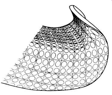
FIG. 43. A bumper jack hook formed from a circle gridded blank.
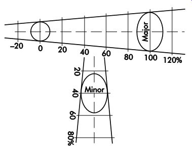
FIG. 44. Circle deformation is measured with a Mylar tape overlay.
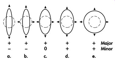
FIG. 45. Examples of deformed circles.
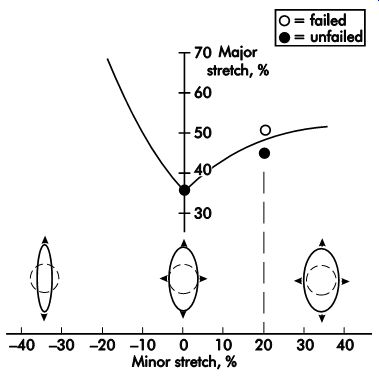
FIG. 46. Measurements are plotted on the forming limit diagram (FLD).
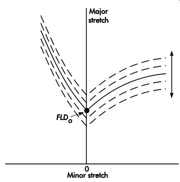
FIG. 47. Different steels move the FLDo point.
Three of the ellipses from FIG. 45 are plotted in FIG. 46. Note that the case of plane stretch (FIG. 45c) is plotted on the vertical axis.
FIG. 47 illustrates an asymmetrical V shaped curve, which is the forming limit. Circles plotted below this curve show no evidence of necking or fracture, while those above it fail. A graph developed in this way is called a forming limit diagram (FLD). The point where the FLD intersects the major stretch axis is called FLDo. Here, only plane strain deformation is occurring.
To initially develop this diagram, many samples of failed versus not failed circles from the same material must be plotted.
The shape of the FLD (FIG. 47) is constant for most low-alloy sheet steel used in automotive, appliance, agricultural, container, and similar industries. It illustrates how the FLD curve can raise or lower for different steel sheets. The level of the FLD-as specified by FLDo-is a characteristic of the sheet steel. For example, a thinner sheet of steel would have a lower FLD than a thicker sheet of steel. In addition, higher-strength steel would have a lower FLD than lower-strength steel. Thus, the location of the curve can be described by specifying the intersection of the curve's FLDo with the minor stretch axis.
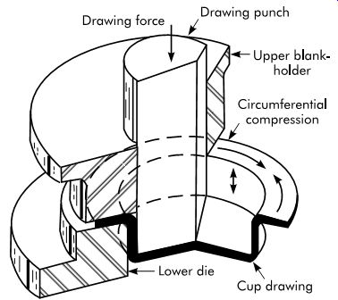
FIG. 48. A simple drawing die.
Deep drawing of cups
FIG. 48 illustrates the forces involved in deep drawing a metal cup. It is important to note that all of the force required for drawing is trans mitted by the draw punch to the bottom of the cup. Very little deformation occurs over the bottom of the punch. Nearly all deformation occurs in the metal restrained by the blank-holder.
The cup-drawing process starts with a flat round blank. The blank is subjected to radial tension and circumferential compression. The metal thickens as it flows toward the draw radius. Deep drawing is unique because of the deformation state of the metal restrained by the blank-holder.
Metal flow
In general, metal flow in deep-cup drawing may be summarized as:
• little or no metal deformation takes place in the blank area that forms the bottom of the cup;
• the metal flow occurring during the forming of the cup wall uniformly increases with cup depth; and
• the metal flow at the periphery of the blank involves an increase in metal thickness caused by circumferential compression.
Success factors The success of a drawing operation depends on several factors, including:
• the formability of the material being drawn;
• limiting the drawing punch force to a lower value than that which will fracture the shell wall; and
• adjustment of the blank-holder force to pre vent wrinkles without excessively retarding metal flow.
Causes of Failure
The maximum force requirement for the drawing process is limited by the tensile failure of the material in the sidewall. As this limit is approached, the metal will neck or thin excessively in a localized area near the punch radius.
Many complex interactions occur during the cup-drawing process. The actual force required depends on the cross-sectional area of the cup wall and the yield strength of the material as it is worked. Should the process fail, some or all of the following factors may be the root causes:
• the ductility or drawability of the stock may be too low;
• the blank-holder force may be too high;
• scoring or galling may be present on the die surfaces;
• the blank-holder geometry and draw radius may not provide for metal thickening and smooth flow into the die cavity;
• there may be an incorrect or insufficient amount of drawing lubricant;
• the depth of draw or percentage of blank reduction may be too great; and/or
• one or more redrawing operations may be necessary to obtain the desired depth of draw.
Annealing may be required between redrawing operations, especially when using materials that work-harden rapidly.
Draw Radius
The blank-holder draw radius should be approximately four to six times the metal thickness for most applications. It has a large effect on the punch force required to pull the metal into the draw cavity. As the metal passes over the radius, it is bent and then straightened to form the sidewall of the drawn cup. If the radius is too small, this can lead to fracture because more force is required to pull the metal over a small radius than a larger one. Also, it will more severely strain the metal, increasing work hardening. This, in turn, requires more force to draw the part.
There is little reduction of drawing force achieved by making the draw radius larger than six times the metal thickness. Approaching a draw radius of 10 times the metal thickness may result in puckering deformation of the metal as it flows over the draw radius. Severe deformation can result in folded metal, which can lock up metal movement and result in fractures.
In cases where all of the metal on the blank holder is to be drawn into the cavity to form a straight-walled shell without a flange, a large radius may result in folded metal as blank-holder control ceases.
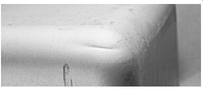
FIG. 49. Localized thinning (necking) at the punch radius indicates a failure
of the drawing process.
Measuring Thickness
Necking failures, such as those shown in FIG. 49, are preceded by localized thinning, which may not be visible in the part. However, the onset of a necking failure can be detected by measuring the metal thickness with an ultrasonic thickness-measuring device.
Application of an ultrasonic thickness gage. The ultrasonic thickness gage is a stamping analysis tool that is useful for online process tracking, troubleshooting, and control. It features a portable control box, which provides thickness readout, and a probe with an ultrasonic transducer.
The principle of operation is much like that of a sonic or sonar depth finder used as a navigational aid by boaters. In its simplest form, a sonic depth finder measures the time between a sonic pulse sent out by a transducer attached to the boat's hull and the arrival of the return echo. The speed of sound in water is a known constant. The delay time between sending the sonic pulse and return echo can be easily converted and displayed in units of depth such as feet, meters, or fathoms. Ultrasonic metal thickness gages work in much the same way.
An ultrasonic pulse is sent out by a handheld transducer, which attaches to the control unit.
The return echo time is short, since the speed of sound in steel is in excess of 16,000 ft/sec (4,877 m/sec). For stamping thickness measurements, the operating frequency is approximately 15 MHz.
A plastic delay line is used between the transducer and the point of contact, with the workpiece being measured so a faint return echo can be detected.
Manufacturer-supplied compliant media is placed between the transducer and plastic delay line.
This media requires periodic renewal to ensure accuracy.
A .125-in. (3.18-mm) diameter transducer is considered better than larger sizes (for example, .250 in. [6.35 mm]), especially for use on curved surfaces. A compliant media is needed between the transducer face and metal workpiece. The best readily available material meeting this requirement is common surgical jelly-a product made to strict quality requirements for uniformity and purity. Be sure to wipe this substance off the part after measurement because it can cause rust.
Tracking thinning. Stampings that are severely drawn or formed usually have one or more areas where thinning is apt to occur. These areas are spots that should undergo regular thickness checks. The areas where a necking failure or fracture is apt to occur on a stamping can be predicted with CGA during the development and die tryout period for new stampings. The failure locations on an existing stamping become well known to pressroom personnel.
Regular checks should be made with an ultra sonic thickness gage. It is helpful to chart the thinning trends in each area. This permits corrective action to be taken before a necking failure becomes visible. Causal factors for a pronounced increase in thinning include:
• excessive blank-holder force;
• material problems such as a lack of ductility or drawability;
• material too thin; and
• scored die surfaces.
Single-action draw dies
The simplest type of draw die is one with a punch and die. Each component may be designed in one piece without a shoe by incorporating features for attaching them to the ram and bolster plate of the press. FIG. 50a shows a simple type of draw die in which the precut blank is placed in the recess on top of the die, and the punch descends, pushing the cup through the die. As the punch ascends, the cup is stripped from the punch by the counterbore in the bottom of the die. The top edge of the shell expands slightly to make this possible. The punch has an air vent to eliminate suction that would hold the cup on the punch and damage it when stripped from the punch.
The method by which the blank is held in position is important, because successful drawing is somewhat dependent on proper control of blank-holder pressure. A simple form of drawing die with a rigid, flat blank-holder for use with .0897 in. (2.278 mm) and heavier stock is shown in FIG. 50b. When the punch comes into contact with the stock, it will be drawn into the die without allowing wrinkles to form.
Another type of drawing die for use in a single action press is shown in FIG. 51. This die is a plain, single-action type where the punch pushes the metal blank into the die using a spring-loaded pressure pad to control the metal flow. The cup either drops through the die or is stripped off the punch by a pressure pad. The figure shows that the pressure pad extends over the nest, which acts as a spacer and is ground to such a thickness that an even and proper pressure is exerted on the blank at all times. If the spring pressure pad is used without the spacer, the more the springs are depressed, and the greater the pressure exerted on the blank; this limits the depth of draw.
Because of the limited pressures obtainable, this type of die should be used with light-gage stock and shallow depths.
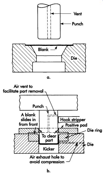
FIG. 50. Draw dies: (a) simple type; (b) simple draw die for heavy stock.
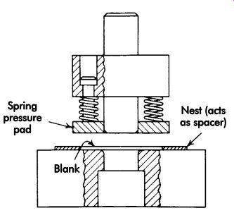
FIG. 51. Draw die with spring pressure pad.
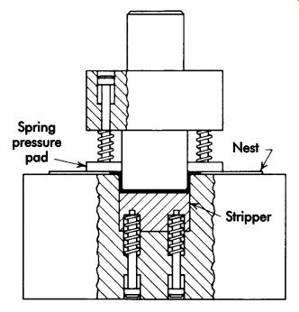
FIG. 52. A draw die with spring pressure pad and stripper.
A single-action die for drawing flanged parts, possessing a spring-loaded pressure pad and strip per, is shown in FIG. 52. The stripper also may be used to form slight indentations or re-entrant curves in the bottom of a cup, with or without a flange. Draw tools in which the pressure pad is attached to the punch are suitable only for shallow draws. The pressure cannot be easily adjusted, and the short springs tend to build up pressure too quickly for deep draws. This type of die is often constructed in an inverted position with the punch fastened to the lower portion of the die.
Deep draws may be made on single-action dies where the pressure on the blank-holder is more evenly controlled by a die cushion or pad attached to the bed of the press. The typical construction of such a die is shown in FIG. 53. This is an inverted die with the punch on the die's lower portion.
Double-action draw dies
In dies designed for use in a double-action press, the blank-holder is fastened to the outer ram, which descends first and grips the blank.
Then the punch, which is fastened to the inner ram, descends, forming the part. These dies may be a push-through type, or the parts may be ejected from the die via a knockout attached to the die cushion or by means of a delayed action kicker. FIG. 54 shows a cross-section of a typical double-action draw die.
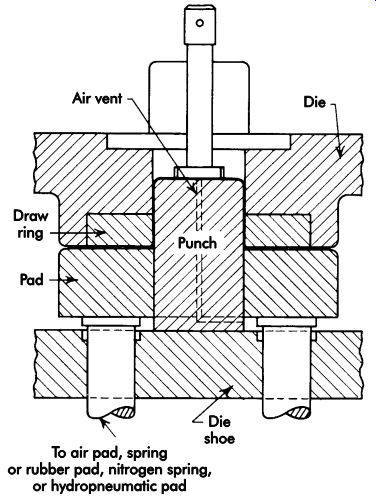
FIG. 53. Cross-section of an inverted draw die for a single-action press;
die is attached to the ram; punch and pressure pad are on the lower shoe.
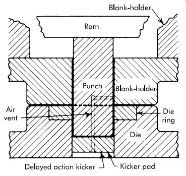
FIG. 54. A typical double-action, cylindrical draw die.
Development of Blanks
First, development of the approximate blank size is done to determine the blank size needed to produce the shell to the specified depth. Secondly, it resolves how many draws will be necessary to produce the shell. Blank development is configured by the ratio of the blank size to the shell size. Various methods have been developed to determine the size of blanks for drawn shells.
These methods may be based on mathematics alone, the use of graphic layouts, or a combination of both. Most of these methods are for use on symmetrical shells.
It is rarely possible to compute blank size to close accuracy or maintain the perfectly uniform height of shells in production because the thickening and thinning of the wall varies with the completeness of annealing. The height of ironed shells varies with commercial variations in sheet thickness, and the top edge varies from square to irregular, usually with four pronounced high spots resulting from the effect of the direction of the metal's crystalline structure. Thorough annealing should largely remove the directional effect. For all of these reasons, it is ordinarily necessary to figure the blank sufficiently large to permit a sizing and trimming operation.
The drawing tools should be made first; then, the blank size should be determined by trial be fore the blanking die is made. There are times, however, when the metal to produce the product is not immediately available from stock. This situation makes it necessary to estimate the blank size as closely as possible by formula or graphically to know what sizes to order.
Blank diameters The following equations may be used to calculate the blank size for cylindrical shells of relatively thin metal. The ratio of the shell diameter to the corner radius (d/r) can affect the blank diameter and should be taken into consideration.
When d/r is 20 or more:
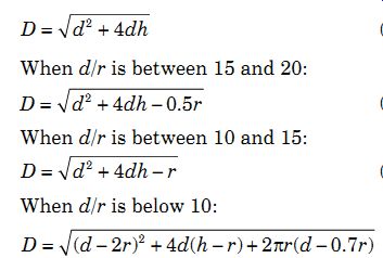
where:
D = blank diameter, in. (mm)
d = shell diameter, in. (mm)
h = shell height, in. (mm)
r = corner radius, in. (mm)
The previous equations are based on the assumption that the surface area of the blank is equal to the surface area of the finished shell.
In cases where the shell wall is to be ironed thinner than the shell bottom, the volume of metal in the blank must equal the volume of metal in the finished shell. Where reduction of wall thickness is considerable, as in brass shell cases, the final blank size is developed by trial. A tentative blank size for an ironed shell can be obtained from:
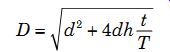
where:
t = wall thickness, in. (mm)
T = bottom thickness, in. (mm) reduction factors
After the approximate blank size has been determined, the next step is to estimate the number of draws to produce the shell and the best reduction rate per draw. For diameter reduction, the area of metal held between the blank-holding faces must be reasonably proportional to the area on which the punch is pressing, since there is a limit to the amount of metal that can be made to flow in one operation. The greater the difference between blank and shell diameters, the greater the area that must be made to flow and, therefore, the higher the stress required to make it flow. General practice has established that, for the first draw, the area of the blank should not be more than 3.5-4 times the cross-sectional area of the punch.
One important factor in the success or failure of a drawing operation is the thickness ratio, or the relation of metal thickness to the blank or previous shell diameter. This ratio is expressed as t/D. As this ratio decreases, the tendency of wrinkling increases, requiring more blank-holding pressure to control the flow properly and prevent wrinkles from starting. The top limit of about 48% seems to be substantiated by practice for single-action first draws. The 30% limit for double-action redraws is dictated by practice and is modified by corner radii, friction, and the angle of blank-holding faces with respect to the shell wall. Because of strain hardening stresses set up in the metal, third and subsequent draws should not exceed 20% reduction without an annealing operation.
Force
Drawing Force
The force applied to a punch necessary to draw a shell is equal to the product of the cross sectional area and yield strength of the metal, as shown in the following:
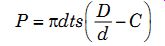
where:
P = force, lbf (kN)
d = shell diameter, in. (mm)
t = wall thickness, in. (mm)
s = yield strength, psi (kPa)
D = blank diameter, in. (mm)
C = constant of 0.6 and 0.7 to cover friction and bending
Blank-holder Force
The amount of blank-holder force required to prevent wrinkles and puckers is largely determined
by trial and error. The force required to hold a blank flat for a cylindrical draw varies from very little to a maximum of about one-third or more of the drawing force. During cylindrical draws, the force is uniform and balanced at all points around the periphery because the amount of flow at all points is the same. On rectangular and irregularly shaped shells, the amount of flow around the periphery is not uniform; therefore, the force required also varies.
Draw Die Design
The first step in planning a die for a part is not the development of the die itself, but the blank for the drawn shell or cup. FIG. 55 shows an example shell, and FIG. 56 shows the die that will make the shell.
Since the ratio d/r is more than 20, the diameter of the blank D is, according to Equation 17:
The area of this blank is slightly less than four times the cross-sectional area of the punch (approximately 4.90 in. ^ 2 [3,162 mm^2 ]). The blank can be drawn into a shell of the dimensions specified in one draw because the ratio of its area to that of the punch nose is approximately 4:1.
The length of the draw radius (radius of the toroidal zone at the entrance to the die) must be determined before any other die design details are considered. The radius of the draw die should be kept as large as possible to aid in the flow; but if it is too large, the metal will be released by the blank-holder before the draw is completed and wrinkle. When the radius is too small, the material will rupture as it goes over the radius or against the face of the punch. TBL. 2 gives the practical drawing radii for certain stock thicknesses. The values in this table are based on a radius of approximately four times the stock thickness. In some cases, the radius may vary from four to six times the stock thickness. The length of the draw radius from TBL. 2 is 9/16 in. (14.3 mm).
The required drawing force is determined with Equation 22:
P = 20 tons (178 kN)
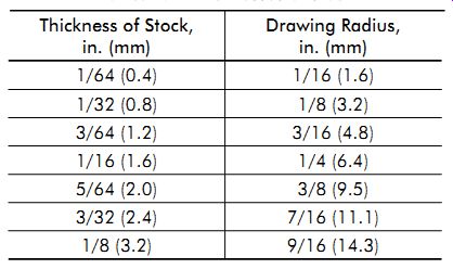
TBL. 2. Practical drawing radii for certain thicknesses of stock
Blank-holder force is largely determined by trial and error. An allowable range is from a few pounds up to one-third of the drawing force; approximately 6 tons (53 kN) is more than adequate. An ordinary 30-ton (267-kN), open backed inclinable press has enough capacity for the total possible maximum force of 26 tons (231 kN) required for the operation.
The blank is nested in a semicircular plate.
Optimum blank-holder pressure is held on the blank during drawing of the shell to thickness specifications. Unit pressure on the blank becomes greater as it is pushed into the die.
Shimming the nest plate will vary the pressure on both the nest and blank, which results in a critical pressure on the latter without producing defective shells.
The blank-holder is a .625-in. (15.88-mm) thick circular plate suspended from the punch-holder by six stripper bolts equally spaced around its circumference. Die springs fit around the bolts and are retained by pockets counter-bored in the punch-holder and blank-holder. In addition to holding the blank, the blank-holder strips the shell from the punch.
The draw clearance (space between the punch and die) from TBL. 3 should be from .138-.140 in. (3.50-3.56 mm). The inside diameter (ID) of the die is 1.638 in. (41.61 mm) for tryout. If there is too much ironing of the shell, this ID can be increased up to approximately 1.640 in. (41.66 mm). The outside diameter (OD) of the draw punch is the same as the ID of the drawn shell.
The methods of determining die dimensions and hold-down size apply to the same elements in a drawing die, but generally may be increased in approximate proportion to the press forces applied and stresses in the die blocks and blank-holders.
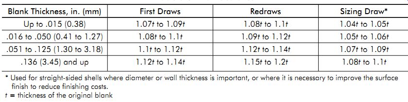
TBL. 3. Draw clearance
Draw Rings
The draw ring of many draw dies is the die itself, made of tool steel with the cavity edge forming a spherical zone over which the metal is drawn. In many large drawing dies, the die is not made in one piece but has an inserted draw ring of tool steel that is replaceable.
Materials
The selection of material for a draw punch and a draw die is determined in the same manner as for any other tool-based upon the number of parts to be drawn and their ultimate unit cost.
For low production, material cost is a major factor. If fewer than 100 parts are to be drawn, a plastic or zinc-alloy material is satisfactory.
For production of a few hundred parts, a plain cast-iron draw ring may be suitable. Cast alloyed irons that are flame hardenable provide excellent wear resistance. Cast-iron punches and dies can be hard-chrome plated or ion nitrided for long production runs. Tool steels should be used for long runs of parts in small dies. The choice of tool steel is based on its wear, strength, hardness, and other characteristics. Carbide punches and dies or carbide inserts may prove to be the most economical for extremely large runs when drawing abrasive materials. Material selection for blank-holders, knockouts, and other parts of a draw die is based on these same factors.
Lubricants
The functional requirements of lubricants for drawing operations are much more demanding than for shafts and bearings. Possible corrosion of compounds on metals and the ease of its removal from drawn metal parts must be considered.
Handbooks and manufacturers of various metals should be consulted for the recommended lubricant for shallow- and deep-drawing operations.
The following lubrication data for drawing mild steel are included as a guide.
For mild operations:
• mineral oil of medium-heavy to heavy viscosity;
• soap solutions (0.03-2%, high-titer soap); and/or
• fat, fatty oil, or fatty and mineral-oil emulsions in soap-base emulsions.
In medium operations:
• fat or oil in soap-base emulsions containing finely divided fillers, such as whiting or lithopone;
• fat or oil in soap-base emulsions containing sulfurized oils;
• fat or oil in soap-base emulsions with fillers and sulfurized oils;
• dissimilar metals deposited on steel plus emulsion lubricant or scrap solution;
• rust or phosphate deposits plus emulsion lubricants or soap solution; and/or
• dried soap film.
For severe operations:
• dried soap or wax film, with light rust, phosphate, or dissimilar metal coatings;
• sulfide or phosphate coatings plus emulsions with finely divided fillers and sometimes sulfurized oils;
• emulsions or lubricants containing sulfur as combination filler and sulfide former; and/or
• oil-base sulfurized blends containing finely divided fillers.
Progressive dies
A progressive die performs a series of fundamental sheet-metal operations at two or more stations during each press stroke to develop a workpiece as strip stock moves through a die.
Each working station performs one or more distinct die operations, but the strip must move from the first through each succeeding station to pro duce a complete part. One or more idle stations may be incorporated in the die, not to perform work on the metal but to locate the strip, facilitate interstation strip travel, provide maximum size die sections, or simplify construction.
The linear travel of the strip stock at each press stroke is called the progression, advance, or pitch, and is equal to the interstation distance. The unwanted parts of the strip are cut out as it advances through the die, and one or more ribbons or tabs are left connected to each partially completed part to carry it through the stations of the die.
The types of operations performed in a progressive die could be done in individual dies as separate operations. However, this would require hand feeding, positioning, and often unloading.
In a progressive die, the part remains connected to the stock strip, which is fed through the die with automatic feeds and positioned by pilots with speed and accuracy.
Selection
The selection of any multi-operation tool, such as a progressive die, is justified by the principle that the number of operations achieved with one handling of the stock is more economical than production by a series of single-operation dies that require discrete handling. Where total production requirements are high, particularly if production rates are large, total handling costs (man-hours) saved by progressive fabrication compared with a series of single operations are frequently greater than the cost of the progressive die. The fabrication of parts with a progressive die is further indicated when:
• stock material is not so thin that it cannot be piloted or so thick that there are stock straightening problems;
• overall size of the die (functions of part size and strip length) is not too large for available presses, and
• total press capacity required is available.
Strip development
Individual operations performed in a progressive die often are relatively simple. However, when combined into several stations, the most practical and economical strip design for optimum operation of the die often becomes difficult to devise. The sequence of operations on a strip and details of each operation must be carefully developed to produce good parts. As the final sequence of operations is developed, the following items should be considered.
• Include pierce piloting holes and piloting notches in the first station. Other holes may be pierced that will not be affected by subsequent non-cutting operations.
• Develop a blank for drawing or forming operations for free movement of metal.
• Distribute pierced areas over several stations if they are close together or close to the edge of the die opening.
• Analyze the shape of blanked areas in the strip for division into simple shapes so punches of simple contours may partially cut an area at one station and cut out remaining areas in later stations. This may suggest the use of commercially available punch shapes.
• Use idle stations to strengthen die blocks, stripper plates, and punch retainers, and to facilitate strip movement.
• Determine whether the direction of the strip grain will hinder or facilitate an operation.
• Plan the forming or drawing operations in an either upward or downward direction, whichever will ensure the best die design and strip movement.
• The shape of the finished part may dictate that the cutoff operation should precede the last non-cutting operation.
• Design adequate carrier strips or tabs.
• Check the strip layout for minimum scrap; use a multiple layout if feasible.
• Locate the cutting and forming areas to provide uniform loading of the press slide.
• Design the strip so that the scrap and part can be ejected without interference.
FIG. 57 shows the use of one die station instead of two to maintain a close-toleranced dimension. If two stations were used, the variation in the location of the stock guides and cutting punches could make it difficult to hold the ±.001 in. (±0.03 mm) tolerance.
The strip development for shallow and deep drawing in progressive dies must allow movement of metal without affecting the positioning of the part in each successive station. FIG. 58 shows various types of cutouts and typical distortions to the carrier strips as the cup-shaped parts are formed and then blanked out of the strip. Piercing and lancing of the strip around the periphery of the part, as shown in a, leaves one or two tabs connected to the carrier strip, which is common.
The semicircular lancing, as shown in b, is used for shallow draws. When this type of relief is used for deeper draws, an extra strain is placed on the metal in the tab, causing it to tear.
The carrier strip is distorted to provide stock for the draw.
A popular cutout for deep draws is shown in c.
The double-lanced relief suspends the blank on narrow ribbons, and no distortion takes place in the carrier strips. Two sets of single, rounded lanced reliefs of slightly different diameters are placed diametrically opposite each other to pro duce the ribbon suspension.
The hourglass cutout in d is an economical method of making the blank for shallow draws.
The connection to the carrier strips is wide, and a deep draw would cause considerable distortion.
An hourglass cutout for deep draws is shown in e, which provides a narrow tab connecting the carrier strip to the blank. The cupping operations narrow the width of the strip as the metal is drawn into the cup shape.
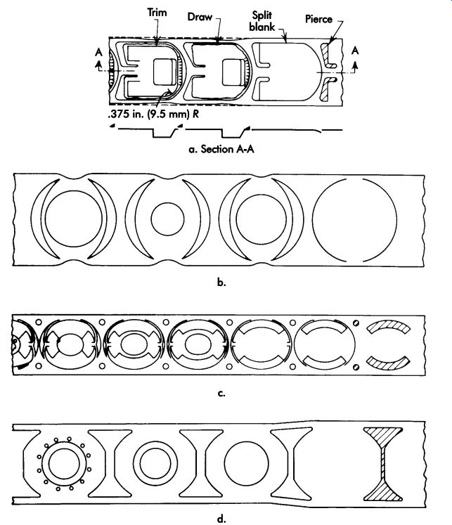
FIG. 58. Cutout reliefs for progressive draws: (a) lanced outline; (b) circular
lance; (c) double-lance suspension; (d) hourglass cutout.
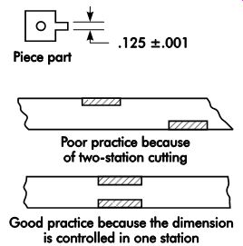
FIG. 57. Use of one station versus two to hold a close tolerance.
FIG. 58. (continued) (e) cutout providing expansion-type carrier ribbon
for circular draws; (f and g) cutout providing expansion-type carrier ribbon
for rectangular draws; (h) I-shaped relief for rectangular draws.
The hourglass cutout may be made in two stations by piercing two separated triangular cutouts in one station, and lancing or notching the material between them in a second station. The cutouts shown in FIGs. 58f and g provide an expansion-type carrier ribbon that tends to straighten out when the draw is performed. These cutouts are made in two stations to allow for stronger die construction.
Satisfactory multiple layouts may be designed with most of the reliefs by using a longitudinal lance or slitting station to divide the wide strip into narrower strips as the stock advances. The I-shaped relief cutout in h is a modified hourglass cutout used for relatively wide strips from which rectangular or oblong shapes are produced.
Straight slots or lances crosswise of the stock are sometimes used on very shallow draws or where the forming is in the central portion of the blank. On deeper draws, this type of relief tends to tear out the carrier strips or cause excessive distortion in the blank and is not satisfactory.
The design of carrier strips for cup drawing in progressive dies tends to be a trial-and-error pro cess. Software programs can give a good approximation of the carrier strip. Another successful method is to use beeswax of the same thickness as the metal to be formed. This material can be forced over wooden forms by hand to simulate the flow of steel in a die. However, the final tool operation and part shape can only be proven in a full size section mock up of the tool, or in the actual finished tool. Often, station-to-station distances must be adjusted to accommodate slight pitch changes that occur as the metal is formed.
Stock positioning
Of prime importance in strip development is the accurate positioning of stock in each station so that the specified operation can be performed in the proper location. A commonly used method of stock positioning is to incorporate pilots in the die.
There are two methods of piloting in dies: direct and indirect. Direct piloting consists of piloting in holes punched in the part at a previous station. Indirect piloting consists of piercing holes in the scrap strip and locating these holes with pilots at later operations. Direct piloting is the ideal method for locating the part in subsequent die operations. Unfortunately, ideal conditions may not exist and, in such cases, indirect piloting must be used to achieve the desired results of part accuracy and high production speeds.
There are two advantages of locating pilots in the scrap material area-they are not readily affected by workpiece change, and size and location are not as limited. Disadvantages of locating pilots in the scrap section are that the material width and lead may increase, and scrap-strip carriers distort on certain types of operations and make subsequent station use impossible.
How to pilot is an arbitrary decision that the tool designer must make. It is impossible to give definite rules and formulas because the material and hardness of the stock influence the decision.
However, in the indirect piloting method, it is possible to use pilots of greater diameter than if holes in the part are used for piloting, such as in FIG. 59a. The greater the diameter of the pi lot, the less chance there is of distortion of either the strip or the pilot. In addition, small-diameter pilots introduce the possibility of broken pilots.
When holes in the part are held to close tolerances (FIG. 59b), it is possible for the pilots to affect the hole size in their effort to move the strip to the proper location. When holes in the part are too close to the edges (FIG. 59c), the weak outer portions of the part are likely to distort on contact with the pilots instead of the strip moving to the correct location. Care should be taken when planning a progressive die to avoid expensive die alterations and the possibility of scrap parts.
Just what constitutes a condition where the edge of the hole is too close to the edge of the part is, like many aspects of design, a matter of personal judgment. Many designers prefer at least twice the stock thickness, although with good stock control one stock thickness or less has been successfully achieved. A similar problem exists when part holes are located in a weak portion of the inside area of the part (FIG. 59d). Here, there is a possibility of the part's buckling before the pilots can position the stock strip. In this case, it is advisable to pilot in the scrap strip.
To achieve accurate part location, the pilots must be placed as far apart as possible. When the holes in the workpiece are close together, as in FIG. 59e, holes in the scrap strip should be used for piloting. A second method is to place a pilot in one hole in one station, then in the same hole in a succeeding station. The feasibility of the second method depends on the availability of an additional die station.
When slots are punched in the blank parallel to the stock movement (FIG. 59e), the slots are not suitable piloting holes. Therefore, indirect pilots must be used.
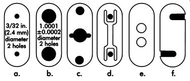
FIG. 59. Part conditions that require indirect pilots: (a) small holes;
(b) close-tolerance holes; (c) holes too near edge; (d) holes in fragile
areas of the part; (e) holes too close together; (f) slots in parts.
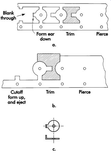
FIG. 60. Alternate strip developments for a workpiece.
Disposition of Scrap Strip
A strip development is illustrated in FIG. 60a using pierce, trim, form, and blank through operations and carriers on both sides of the strip. The workpiece is dropped through the die, while the carrier bars continue to the scrap cutters to be cut into short lengths. Drop ping the workpiece through the die is the most desirable method of part ejection, but this cannot always be accommodated. Cutting the scrap into small sections simplifies material handling and produces a greater dollar return when it is sold as scrap metal. FIG. 60b shows an alternate strip development with one side carrier. The workpiece is pierced, trimmed, cut off, and formed on a pad with air or gravity ejection, and the carrier bar is cut into short pieces by the scrap cutter. Re member that if a part is to be ejected, as this one is, the double-carrier bar design in FIG. 60a should be avoided because the part may become trapped in these bars and cause die damage.
The design of the part in FIG. 60c requires that the carrier be outside the part configuration.
This necessitates the use of stock wider than the part width plus the normal trimming allowance.
The part shown in FIG. 61a can be made of stock the same width as the part.
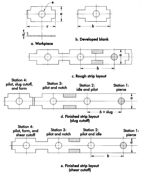
FIG. 61. Scrapless strip development.
FIG. 61d illustrates how the strip is pierced, trimmed, and the part cut off and formed.
A slug-type cutoff punch is used and the flange is formed downward. The part then is ejected by an air jet or by gravity. This arrangement often is referred to as scrapless development since no carrier strips remain after the part is cut from the strip.
FIG. 61e shows strip development for the same part using a shear-type cutoff. The flange is formed upward as the combination cutoff and form punch descends. A spring-loaded pad sup ports the workpiece during forming and assists in ejecting the part from the die. The progression of this type of development is shortened by the width of the cutoff slug.
FIG. 62 shows another development in which the stock is the same as the developed width of the workpiece. The strip is pierced in station 1; piloted and notched in station 2; and piloted, pierced, and formed in station 3.
Die design
The die elements used in progressive dies, such as punches, stops, pilots, strippers, die buttons, punch guide bushings, die sets, guideposts, and guidepost bushings, are of similar design to those used in other types of dies.
A progressive die should be heavily constructed to withstand the repeated shock and continuous runs to which it is subjected. Precision or anti friction guideposts and bushings should be used to maintain accuracy. When also serving as guides for punches, the stripper plates (if spring-loaded and movable) should engage the guide pins before contacting the strip stock. Lifters should be provided in die cavities to lift up or eject the formed parts, and carrier rails or pins should be provided to sup port and guide the strip when it is being moved to the next station. A positive ejection method should be provided at the last station. Where practical, punches should contain shedder or oil-seal-breaker pins to aid in the disposal of the slug. Adequate piloting should be provided to ensure proper location of the strip as it advances through the die.
FIG. 61a shows a workpiece to be blanked and formed at high volumes in a progressive die.
The first step in die design is the development of the blank (FIG. 61b). The grain of the coiled metal is normally parallel to the length of the strip. Where possible, forming operations are performed perpendicular to the grain to forestall any tendency to fracture. Therefore, the workpiece is sketched with the bend line perpendicular to the strip.
The a dimension appears to coincide with stock width. A comparison is made between the exact dimension with tolerance and available purchased coil stock. If the a dimension is not within the slitting tolerance of the purchased stock, the part must be blanked from a wider strip and perhaps shaved to the finished dimension. In this case, the a dimension is within the slitting tolerance; the slit edge will be satisfactory; and no additional work is needed to obtain the dimension.
The b dimension is developed by adding the c dimension, d dimension, and a bend allowance.
Tolerances must be carefully considered in developing the b dimension, which will determine whether it can be achieved with a single shear or whether shaving will be required. In this case, the b dimension is not critical and is, for the moment, accepted as the station-to-station distance.
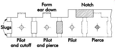
FIG. 62. Four-station strip development.
With the a and b dimensions established, a centerline is drawn and the template of the blank traced along the centerline (FIG. 61c). The areas from which stock must be removed are clearly indicated. The straight edges of the stock appear acceptable for guidance. The absence of scrap stock on either side of the workpiece determines that the strip must be piloted by registering workpiece features. Hole e appears most suitable for piloting. The dimensions of the hole are examined to determine whether it can be pierced convention ally (hole diameter is not less than 1-1/2 times stock thickness) or if a secondary operation may be needed. Hole dimensions in this case are not critical, so the hole can be pierced in the first station and used as a pilot in subsequent stations. The first station now can be drawn, which will include a stock guidance method that establishes the height of the punch and the die. The punch location can be transposed to the other stations where it will indicate the presence of a bullet-nosed pilot.
As the strip enters the second die station, it will register on the pilot. The next operation required on the workpiece is notching of the edges. The workpiece dimensions are such that the notching should be performed by one stroke in one station. A preliminary layout discloses, however, that a notching operation in the second die station would be close to the piercing operation of the first station. Thus, the second station is tentatively designated as an idle station.
Idle stations are of great value. They enable the designer to distribute the workload uniformly throughout the length of the die. Individual die details consequently can be less complex and easier to build and maintain. Idle stations also permit later changes in workpiece design by providing space for added operations.
The third die station can now be drawn to include a pilot and the notching punches.
The stock strip will enter the fourth die station and register on the pilot. Two operations are required to finish the workpiece: the leading edge must be formed 90°, and the workpiece must be separated from the strip. Once the workpiece has been separated, no further operations are normally possible, but the workpiece must be separated for forming. The two operations can, however, be performed simultaneously in one station, just as the two sides were notched in one station. Two methods may be considered. If the stock is to be separated by removing a slug, the width of the slug must be added to the b dimension, and the station to-station distance of the entire layout must be correspondingly amended. This method, however, would permit a second punch to simply wipe down (form) and thereby complete the part without changing the elevation of the stock. If the separation is to be performed by direct shear without a slug, the workpiece must change elevation. The die station would be spring loaded to permit the shear action, and the forming action would take place at the depressed level.
FIG. 63 shows the proposed die, including stock elevation, stripper pads, and the ejection method. Section A-A shows the die construction for a shear-type cutoff.
Force Determination
The force required for each piercing station is computed. Bending forces are covered by the methods discussed earlier in this section. The total workload will be the sum of the force of each piercing station and bending through their points of application. In addition, the spring, die cushion, or nitrogen forces are determined. The sum of all of the forces required for each operation, together with these forces, is the theoretical maximum force required. Note that since the operations typically do not occur at the same time as the die closes, the total force figure may be conservative.
If the workload has been properly distributed throughout the length of the die, no rocking action should occur. If the required force is concentrated in any one station or area of the die, the planned operations should be shifted to achieve balance. When reasonable balance is ensured, the forces may be added to determine the required press capacity.
An error often made when balancing forces, even with the aid of a correctly installed tonnage monitor, is the sequence of operations that occur as the die closes. If there is a high cutting load on one end of the die and an embossing or coining load on the other, the ram will be deflected even though the loads are equal because they do not occur simultaneously.
Press Selection
The press selected must be of adequate capacity for the planned operation and must be able to withstand the overloads that may be accidentally encountered. It must be equipped with a precise stock-feeding mechanism. The bolster plate must not deflect excessively under the planned load, even after it has been weakened by milling an opening for slug disposal. The die sets are commercially available in a wide variety of sizes. Some shops prefer to make their own die sets. The quality of the die set chosen is influenced by the speed of the operation, accuracy required, and anticipated production during the life of the die.
Examples
The part to be made is a small clip, FIG. 64, made of .008-in. (0.20-mm) thick phosphor bronze, eight numbers hard. Because of the delivery date for the parts and anticipated total production, it was decided to pierce and blank the part in a progressive die, then form it in a separate die.
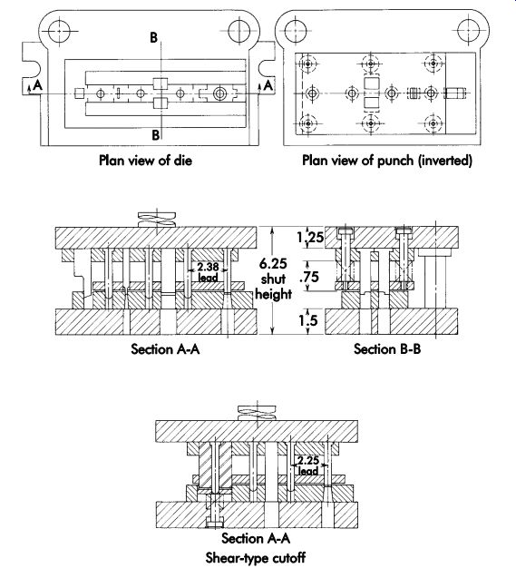
FIG. 63. Die for part in FIG. 61.
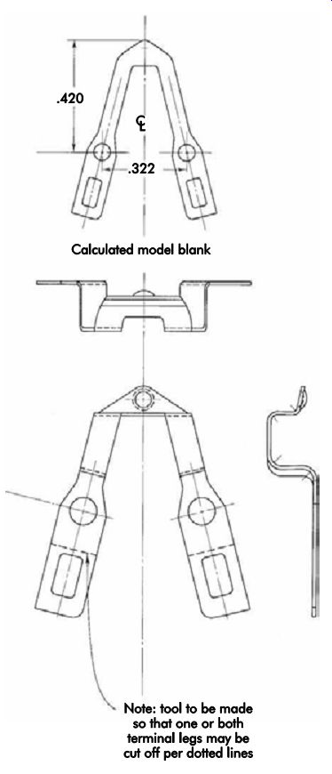
FIG. 64. Phosphor bronze clip blanked in a progressive die.
The product designer indicated that the grain direction for optimum part performance is to be perpendicular to the bends, which will decrease the tendency of cracking at the bend lines.
The pilots were located in the scrap area of the strip to:
• allow for any future design changes;
• avoid thin walls on the blanking punch if pilots were inserted in the holes of the part, and
• take the opportunity to use larger-diameter pilots, since the part holes are only .0655 in. ±.0015 in. (1.664 mm ±0.038 mm) in diameter.
The perimeter of the blank and holes to be pierced is about 2.54 in. (64.5 mm). Multiplying the length of cut by the stock thickness of .008 in. (0.20 mm) and a shear stress of 80,000 psi (552 MPa) gives a shear load of approximately 1,600 lb (726 kg). Therefore, the size of press will be more dependent on the die area than the capacity.
FIG. 65 shows strip development for the part. In the first station, the two .067/.064-in. (1.70/1.63-mm) diameter holes are pierced, the tip of the blank dimpled, and a .094-in. (2.39-mm) diameter pilot hole is pierced. When the full length legs are required, station 2 is a piloting station only. When one or both of the legs are to be cut off, punches are inserted in this station.
In station 3, the strip is piloted and two rectangular holes are pierced. In station 4, the strip is piloted while the part is blanked through the die.
There are clearance spots on the die blocks for the dimple, thus permitting the strip to be flat on the die blocks. The die blocks are made in three sections for ease of machining, as shown in Figure 66. A channel-type stripper, 1, was selected for this die because of its more reasonable cost, and less design and build time. The forming die in the second operation would remove some of the curvature caused by the blanking operation.
Hardened guide bushings, 2, were used for the pilot-hole piercing punch, 3, and the punches, 4, for the .067/.064 in. (1.70/1.63-mm) diameter holes. Guide bushings were used with these punches since they were small in diameter and for the most important holes in the part.
The punches, 5, for cutting off the legs were backed up with a socket setscrew, 6. When the punches are not to be used, screws are backed off a few turns and the tight fit between the punch and punch-holder holds them away from the stock.
This process is called "gagging" the punch.
A 5.00 × 5.00-in. (127 × 127-mm), two-post precision die set was selected for the die. The lower shoe was 1.50 in. (38.1 mm) thick and the upper shoe was 1.25 in. (31.8 mm) thick with a 1.5625-in. (39.688-mm) diameter by 2.125-in. (53.98-mm) long shank.
The stripper was extended beyond the die set close to the push-type roll feed. This was to sup port the stock and avoid buckling and subsequent damage to the die.
FIG. 67 illustrates the die layout for a small, irregularly shaped stamping with eight small holes and one large hole. For accurate positioning of the strip, pilots are provided in each station. There are six stations in the die with progression of 1.718 in. (43.64 mm) between stations.
In station 1, the eight holes, the .1875-in. (4.763-mm) diameter pilot hole, and a .302 × .259 in. (7.67 × 6.58 mm) hole are pierced. In station 2, a .50-in. (12.7-mm) diameter hole, two .062 × .068 in. (1.57 × 1.73 mm) holes, and a .095 × .379 in. (2.41 × 9.63 mm) slot are pierced. In station 3, a slot is pierced symmetrically about the centerline. The strip is notched and slotted in the next station. Station 5 is an idle station because of the length of the notching punch in the previous station. The last station, 6, incorporates a slug-type cutoff punch. This punch trims the left-hand side of the blank piloted in station 5 and the right-hand side of the blank in station 6.
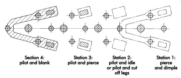
FIG. 65. Strip development for part in FIG. 64.
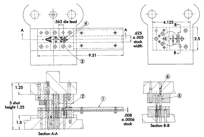
FIG. 66. Progressive die for part in FIG. 64.
For ease of grinding, a die was made in five segments as shown in FIG. 68. The special die set was made with diagonally placed guideposts. One post is 1.50 in. (38.1 mm) in diameter, while the other is 1.25 in. (31.8 mm) in diameter. Guideposts of two different diameters were used to prevent placing the upper shoe on the lower shoe incorrectly and damaging the punches.
Die buttons in the lower die steels were used for each of the piercing punches. This feature allows changing high-wear items without the need to fabricate a completely new lower die section.
The die also incorporated guide bushings in the channel stripper. This is because the piercing punches have a relatively small diameter and can deflect, causing imprecise location.
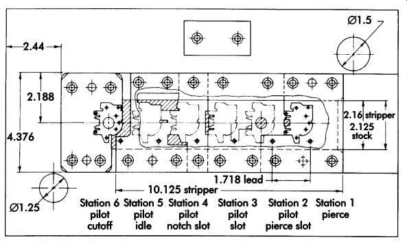
FIG. 67. Die layout for a small, irregularly shaped stamping.
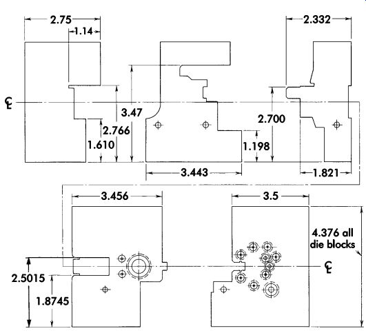
FIG. 68. Details of die blocks for die in FIG. 67.
Extrusion
Impact extrusion, also known as cold extrusion or cold forging, is closely allied to coining, sizing, and forging operations. The operations generally are performed in hydraulic or mechanical presses. The press applies sufficient pressure to cause plastic flow of the workpiece material (metal) and form the metal to a desired shape.
A metal slug is placed in a stationary die cavity into which a punch is driven by the press action.
The metal is extruded upward around the punch, downward through an orifice, or in any direction to fill the cavity between the punch and die. The finished part's shape is determined by the shape of the punch and die.
Impact extrusion dies are classified as open or closed. In open dies, the metal does not completely fill the die cavity. In closed dies, the material fills out the details of the die. To compensate for variations in slug volume, it is desirable to relieve closed dies and thus minimize excessive pressures.
Product design is influenced by methods of manufacturing, such as machining from the solid, drawing, spinning, stamping, or casting. Impact extrusion may combine more manufacturing processes into a single operation than any other metalworking method. Cold extrusion can result in excellent surface finish and accurate size, and can improve the mechanical and physical properties of the workpiece material. Cold-extruded parts may have smooth surfaces ranging between 30-100 ?in. (0.8-2.5 ?m). Close tolerances can be achieved by cold extrusion. Severe cold working of the metal develops a fine, dense grain structure parallel to the direction of metal flow.
These continuous flow lines increase the fatigue resistance of the material.
Pressure
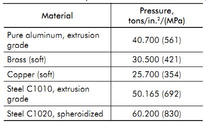
TBL. 4. Extrusion pressures for common metals
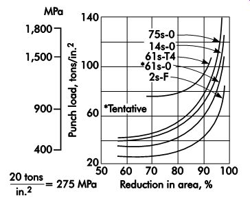
FIG. 69. The effect of reduction in area on the punch load in extruding.
TBL. 4 lists the pressures required to extrude common metals. The pressures required depend on the alloy and its microstructure, restriction to flow, severity of work hardening, and lubricant used. With high speed and restricted flow, the press load may suddenly increase to three times the anticipated tonnage requirement.
Pressures have been recorded up to 165 tons/in.^2 (2,275 MPa). Because of the high pressures required, presses must be carefully selected and dies properly sized to resist extreme loads.
The pressures required for extrusion also depend on the percentage of reduction in area.
When the percentage of reduction of area for parts made of various aluminum alloys is known, the required pressure may be taken from FIG. 69. Although the alloys mentioned usually are extruded at room temperature, a reduction in press pressure can be achieved by extruding at elevated temperatures. Wall thickness of the part is a close relation and a factor in establishing reduction of area. The increasing affect on punch pressure as the wall becomes thinner is illustrated in FIG. 70.
The relationship between reduction of area and extrusion pressures for a series of plain carbon steels is shown in FIG. 71. The steels referred to in the different curves have a carbon content in the range of 0.05-0.50%, and less than 0.03% each of sulfur and phosphorus.
Steel 11 contains 0.58% chromium, 0.11% carbon, and 0.36% manganese, and 0.03% each sulfur and phosphorus.
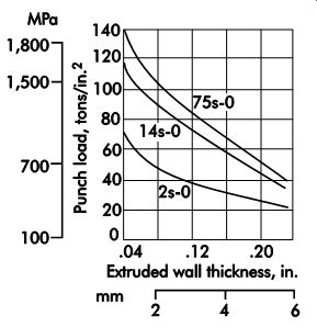
FIG. 70. The effect of extruded wall thickness on the punch load.
Lubrication
Correct lubrication reduces the pressures required and makes possible the cold extrusion of steel. Ordinary die lubricants break down because of the high pressures and the excessive surface heat generated by the plastic flow of material.
A bonded steel-to-phosphate layer and bonded phosphate-to-lubricant layer are satisfactory to prevent metal-to-metal welding or pickup. The workpiece usually is phosphatized before extrusion. If the workpiece is subjected to several ex trusion operations, it usually must be annealed and phosphatized between operations.
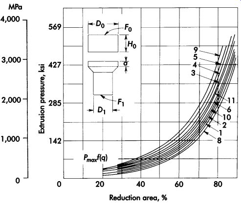
FIG. 71. Extrusion pressures: reduction relationship for the forward extrusion
of a series of steels with carbon contents in the range of 0.005-0.50%.
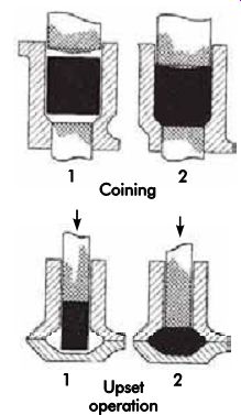
FIG. 72. Slug coining and upsetting.
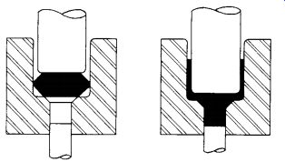
FIG. 73. Profiled slugs.
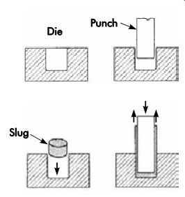
FIG. 74. Backward extrusion.
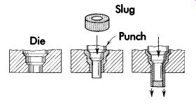
FIG. 75. Forward extrusion.
Slugs
Because the slugs used for impact extrusion are cut from commercial rod or bar, it is desirable to coin them to a desired size and shape for better die-fitting characteristics before extrusion.
Using coiled wire stock, headers can be used to cut and coin or upset as a continuous high speed operation. FIG. 72 illustrates slug coining and upsetting. FIG. 73 illustrates how a profiled slug fits the die cavity and how the material flows when pressure is applied to cause plastic flow. Voids in the die cavity are filled as the slug collapses under initial pressure. Pro filed slugs thus cushion the impact of the punch and allow higher ram velocity. Plastic flow then continues through small orifices between the die pot and the punch.
Methods
Basic methods of impact extrusion are back ward, forward, and combination methods. In backward extrusion (FIG. 74), metal flows in a direction opposite to the direction of punch movement. The punch speed can be from 7-14 in./sec (178-356 mm/sec). As the punch strikes the slug, the heavy pressure causes the metal to flow through the orifice created by the punch and die, and forms the sidewall of the part by extrusion. In forward extrusion (FIG. 75), plastic flow of metal takes place in the same direction as punch travel. The orifice in this case is formed between the extension on the punch and the opening through the die. To prevent reverse metal flow, the body of the punch seals off the top of the die. The finished part is ejected backward after the punch is withdrawn from the part.
The design of a punch and die with double orifices to permit the plastic flow of metal in for ward and reverse extrusion simultaneously will produce parts by combination impact extrusion.
FIG. 76 illustrates examples of combination extrusion.
die design Coining Dies
In backward extruding dies, the punch is always smaller in diameter than the die cavity.
This gives a clearance between punch and die equaling the desired wall thickness of the part
to be produced. The punch is loaded as a column.
To minimize punch failure, it is desirable to coin the slugs to a close fit in diameter to ensure con centricity. FIG. 77 illustrates a coining die to prepare a slug for backward extrusion. Coining the slug to fit the die pot and coining the upper end to fit and guide the free end of the punch will minimize punch breakage of the extruding die.
Backward Extrusion Dies
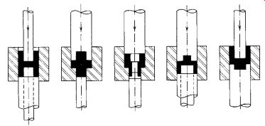
FIG. 76. Combination extrusion. (American Machinist)
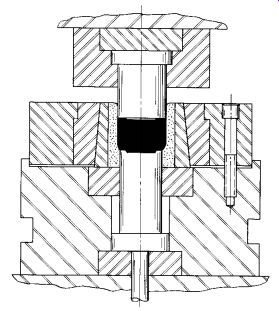
FIG. 77. Coining die for slug preparation.
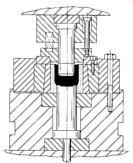
FIG. 78. Backward extrusion die. Note that the centering ring for the punch
and the carbide die cavity are preloaded in shrink rings and supported on
toughened, load-distributing steels.
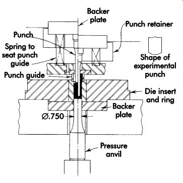
FIG. 79. Backward extrusion die.
FIG. 78 shows a typical backward extrusion die. The use of a carbide die cavity will minimize wear due to excessive pressures. The carbide insert is shrunk into a tapered holder. The holder has a 1° side taper that pre-stresses the carbide insert to minimize expansion and fatigue failure. The inserts are well supported on hardened blocks.
The extruding punch is guided by a spring-loaded guide plate, which in turn is positioned by a tapered piloting ring on the lower die. Ejection of the finished part from the die is by cushion or pressure cylinder. FIG. 79 illustrates a backward extrusion die with an unusual punch penetration ratio of 5:1 made possible with a modified flat-end punch profile.
Forward Extrusion Dies
FIG. 80 is an example of a typical forward extrusion die in which the metal flows in the same direction as the punch, but at a greater rate due to change in the cross-sectional area.
A lower carbide guide ring is added to maintain straightness. The nest above the upper carbide guide ring serves as a guide for the punch during the operation.
Combination extrusion
FIG. 81 illustrates another forward extrusion die in which the punch creates an orifice through which the metal flows. The extruding pressure is applied through the punch guide sleeve.
A typical combination forward and backward extrusion die is shown in FIG. 82. In this die, the two-piece pressure anvil acts as a bottom extruding punch and shedder. The upper extruding punch is guided by a spring-loaded guide plate, into which the guide sleeve is mounted.
To maintain concentricity between the punch and die, the punch guide sleeve is centered into the die insert.
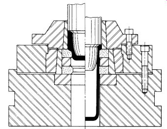
FIG. 80. Forward extrusion die.
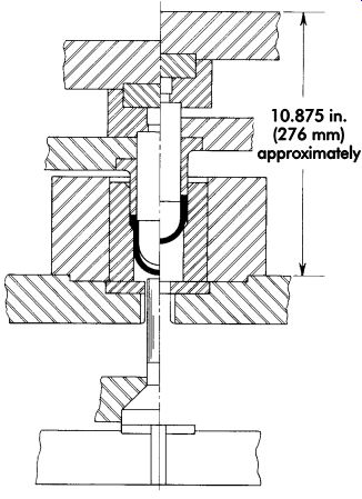
FIG. 81. Combination extrusion die.
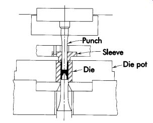
FIG. 82. Combination extrusion die with two-piece pressure anvil.
Punch Design
The most important feature of the punch's design is the end profile. A punch with a flat end face and corner radius not over .020 in. (0.51 mm) can penetrate three times its diameter in steel, four to six times its diameter in aluminum. A punch with a bullet-shaped nose or a steep angle will cut through the phosphate-coat lubricant quicker than a flat-end punch. When the lubricant is displaced in extrusion, severe galling and wear of the punch will take place. The punch must be free of grinding marks and requires a 4 ?in. (0.10 ?m) finish, lapped in the direction of metal flow.
The punch should be made of hardened tool steel or carbide. In some backward extrusion dies, a shoulder is provided on the punch to square up the metal as it meets the shoulder.
Pressure Anvil Design
The function of the pressure anvil is to form the base of the die pot, act as a bottom extruding punch, and as a shedder unit to eject the finished part. Heat treatment and surface finish requirements are the same for pressure anvils as they are for punches.
Die pot design
To resist die pot bursting pressure, the tool steel or carbide die ring is shrunk into the shrink ring or die shoe. The die shoe normally is in compression. A shrink fit of .0040 in./in. (0.004 mm/mm) of the diameter of the insert is desirable. Material, heat treatment, and finish requirements of the die pot are the same as for the punch. The recommended material for shrink rings is hot-worked alloy tool steel hardened to Rockwell C 50-52. A two-piece die pot insert is sometimes used for complex work piece shapes.
Punch Guide Design
The guide ring minimizes the column loading on the punch by guiding it above the die pot. The spring-loaded guide sleeve pilots the punch into the die pot and maintains concentricity between them. The guide ring can also act as a stripper. The proper use of guide sleeves permits higher penetration ratios.
References
Committee of Sheet Steel Producers. 1984. Sheet Steel Formability, August 1. Washington, DC: American Iron and Steel Institute.
Keeler, S. 1986. Circle Grid Analysis (CGA). Livonia, MI: National Steel Corporation Product Application Center.
--. 1969. From Stretch to Draw. Technical Paper MF69-513. Dearborn, MI: Society of Manufacturing Engineers.
Paquin, J. R. 1962. Die Design Fundamentals. New York: Industrial Press.
Smith, D. 2004. Quick Die Change, Second Edition. Dearborn, MI: Society of Manufacturing Engineers.
--. 2001. Die Maintenance Handbook. Dearborn, MI: Society of Manufacturing Engineers.
--. 1994. Fundamentals of Pressworking. Dearborn, MI: Society of Manufacturing Engineers.
--. 1990. Die Design Handbook. Section 3, "Die Engineering-Planning and Design." Section 6, "Shear Action in Metal Cutting." Dearborn, MI: Society of Manufacturing Engineers.
Tharrett, M. 1987. Computer-aided Formability Analysis. Die and Pressworking Tooling Clinic, August 25-27. Dearborn, MI: Society of Manufacturing Engineers.
Wick, C., et al., eds. 1984. Tool and Manufacturing Engineers Handbook, Fourth Edition. Volume 2, Forming. Dearborn, MI: Society of Manufacturing Engineers.
Other Refs.
The Society of Manufacturing Engineers (SME) has developed the Fundamentals of Tool Design video series, which comprises nine DVDs, of which two relate directly to this section's content: Progressive Die Design (18 minutes), and Troubleshooting Tool and Die Making (20 minutes).
Progressive dies perform fundamental cutting and forming operations simultaneously at various stations within a die during each press stroke.
The Progressive Die Design program explores the design variables used in part/strip development that contribute to part quality, progressive die tool maintenance, tool life, and tool cost, including part orientation, part transport, stock positioning, and the number of progressions. Also examined is the effective use of lubricants in progressive dies to control friction, extend tool life, and improve surface quality of parts.
The Troubleshooting Tool and Die Making program examines the many issues that may arise in the tool and die making process, explaining possible causes and providing suggestions to troubleshoot problems. Some of the industries and processes explored include stamping, forging, extrusion, powder metallurgy, and injection molding.
QUIZ
1. What is the most common pressworking operation?
2. How is clearance typically determined between the punch and die for die-cutting operations?
3. What is meant by "center of pressure?"
4. How is the theoretical peak cutting force determined?
5. How are cutting forces reduced during press operations?
6. What must occur to form a bend in a finished part?
7. How is the size of a curl governed? What are the limits of a curl?
8. What method of forming is used to produce medallions?
9. What are the advantages of using a rubber or polyurethane forming die?
10. What usually defines a compound die?
11. What is the function of an ultrasonic thickness gage?
12. What considerations need to be given in selecting lubricants for drawing operations?
13. What defines a progressive die operation?
14. Name the basic methods of impact extrusion.