A power press is a machine that supplies force to a die used to blank, form, or shape metal or nonmetallic material. Thus, a power press is a component of a manufacturing system that combines the press, die, material, and feeding method to produce a part. A press is composed of a frame, bed, or bolster plate, and a reciprocating member called a ram or slide, which exerts force upon work material through special tools mounted on the ram and bed. Energy stored in the rotating flywheel of a mechanical press (or supplied by a hydraulic system in a hydraulic press) is transferred to the ram to provide linear movement. The system designer specifies the proper point-of-operation guards to safeguard pressroom personnel.
Gap-Frame Presses
Gap-frame or C-frame presses derive their name from their C-shaped throat opening. These presses have many useful features, including excellent accessibility from the front and sides for die setting and operation. The open back is available for feeding stock and ejection of parts and scrap.
Another advantage of a gap-frame press is that it is easier to set up than a straight-side press. The die setter has much greater access to locate and bolt the die in place. Gap-frame presses generally have less height than a straight-side press of comparable tonnage. This is a valuable consideration when overhead clearance is limited.
Gap-frame presses with force capacities up to 250 tons (2,224 kN) and larger are less costly than straight-side presses having the same force capacity. In the 35-60-ton (311-534-kN) range, a gap-frame press costs approximately half that of a straight-side press.
For a given load, a gap-frame press has more deflection than a straight-side press. The deflection has both a vertical and an angular component. The angular deflection or misalignment that occurs is due to the spreading of the throat opening as tonnage is developed. In many applications, this angular misalignment under load may not be objectionable.
Popular for short-run work, gap frame presses are specified where high accuracy of die alignment and close part tolerances are not necessarily controlling factors. For low-tonnage, high-speed work, precision gap presses are widely used.
Here, the work is done before the bottom of the stroke. Light loading helps avoid angular deflection problems. However, straight-side presses are generally recommended for any application in which angular machine deflection would cause unacceptable part quality and accelerated die wear. The lower cost of gap-frame construction machines may be poor economy if accelerated tooling wear and quality problems result.
Open-back Inclinable
Type FIG. 1 illustrates three types of gap-frame presses. Two of these (a and b) are a style of ma chine known as the open-back inclinable (OBI) press. The press frame is secured in a cradle, which permits the machine to be inclined backward. This is done to facilitate gravity loading, as well as part and scrap discharge out of the open back of the press.
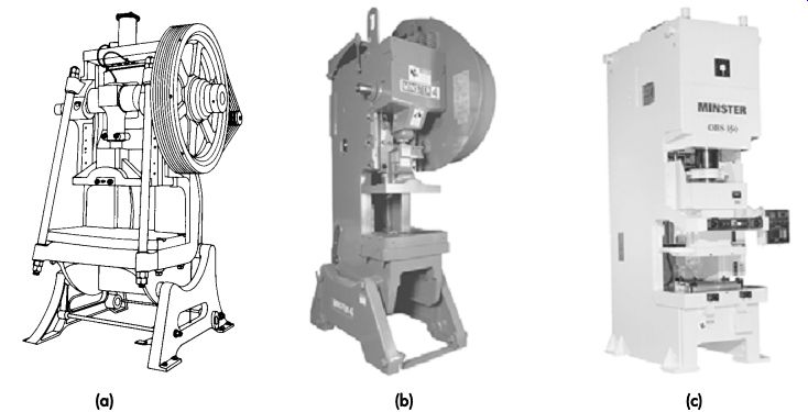
FIG. 1. (a) Shown are an older style, unguarded open-back inclinable (OBI)
gap-frame press with tie-rods added to reduce angular deflection; (b) a modern
gap-frame, OBI single-pitman mechanical press; (c) a modern open back stationary
(OBS) press featuring eccentric drive and a guided plunger connection.
The frames of most older OBI presses are made of cast construction. The most commonly used materials are gray cast iron or steel. FIG. 1a illustrates two pre-tensioned tie-rods across the open front of the machine. Lugs are cast into the frame of the machine to accept the tie-rods, which are installed as an option to reduce angular deflection.
The development of timed air blow-off devices and a variety of small conveyors have lessened the demand for the OBI-style press. Today, many OBI presses are operated in the vertical position. While the OBI style is not obsolete, many press builders supply this type only on special order.
Open-back stationary
Type The open-back stationary (OBS) gap-frame press shown in FIG. 1c is more compact and often a more robust machine than the older OBI style that it has largely replaced. The OBS press has a heavy, box-like structure. The one in FIG. 1c features a guided plunger connection and eccentric drive.
Straight side presses
Straight-side presses derive their name from the vertical columns or uprights on either side of the machine. The columns together with the bed and crown form a strong housing for the crank shaft, slide, and other mechanical components.
The housing or frame of most straight-side presses is held together in compression by pre stressed tie rods. Some straight-side presses have solid frames. Generally, a solid-frame straight side press is less expensive than one with tie rods. However, tie-rod presses are easier to ship disassembled and can better withstand overloads.
A major advantage of the straight-side press compared to the gap-frame machine is freedom from angular misalignment under load. Maintaining true vertical motion throughout the press stroke minimizes tool wear and achieves accurate part tolerances.
Components
FIG. 2 illustrates some of the principle mechanical components of a straight-side press with double-end drive gears and two connections. The bed is the base of the machine. The columns support the crown. It also has gibs or gibbing attached to guide the slide. The crank shaft end bearings may be contained in the columns or crown.
The crown serves many functions, depending upon the machine's design. Typically, the clutch, brake, motor, and flywheel mount on the crown of the press. The gears shown in FIG. 2 may be open, having only a safety guard designed to contain the gear in case it should fall off due to a failure, such as a broken crankshaft. In modern designs, the gears are fully enclosed and run in a bath of lubricant. Housing them in separate enclosures permits the use of a heavier viscosity lubricant than that used for other machine parts, such as the bearings. The latter are often sup plied from a recirculating lubricant system. The separate gear housing and lubricant bath system serves to lessen noise and ensure long gear life.
FIG. 3 illustrates the placement of pneumatic piping tanks and controls for a typical straight-side press. The system is typical of a good pneumatic arrangement for a press equipped with an air-actuated friction clutch and die cushions.
Production of precision stampings
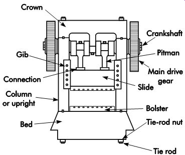
FIG. 2. A straight-side mechanical press with double-end drive gears and
two connections (Smith 2001).
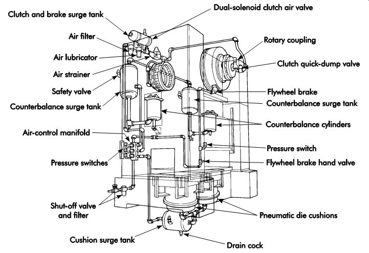
FIG. 3. Pneumatic piping, tanks, and controls installed on a straight-side
press.
Many high-volume, close-tolerance stampings are made in straight-side presses. These include electrical connectors, snap-top beverage cans, spin-on oil filter cartridge bases, and refrigeration compressor housings. Tiny computer connectors are stamped at press speeds of 1,800 strokes per minute (SPM) or more. Often, two to eight or more parts are completed per hit. Precision stampings also are produced at low speeds. For example, large refrigeration compressor housings may be stamped at press speeds of approximately 12 SPM. The housing consists of two mating halves, which must fit together precisely to properly align the internal parts.
Mechanical versus hydraulic presses
Mechanical presses are built with force capacities to 6,000 tons (53.4 MN) or more. On hydraulic presses, force capacities of 50,000 tons (445 MN) or more are available. Large hydraulic machines are used in hot- and cold-forging applications, as well as various rubber-pad and fluid-cell-forming processes. Both single- and double-action hydraulic presses are used for forming large parts for the automotive and appliance industries.
Features
Deep drawing and forming applications often require large forces high in the press stroke, all the way to the bottom of the stroke. Some mechanical presses do not develop enough force high enough in the downward stroke to permit severe drawing and forming applications.
In most hydraulic presses, full force is available throughout the stroke-an important characteristic. FIG. 4 illustrates why the rated force capacity of a mechanical press is available only near the bottom of the stroke. Another advantage is that the stroke may be adjusted to match the job requirements. Only enough stroke length to provide part clearance is required. Limiting the actual stroke will permit faster cycling rates and reduce energy consumption. Ram speed also can be adjusted to a rate that is best for the material's requirements.
Overload protection
The force that a hydraulic press can exert is limited to the pressure applied to the total piston area. The applied pressure is limited by one or more relief valves. A mechanical press usually can exert several times the rated maximum force in case of an accidental overload. This extreme overload often results in severe press and die damage. Mechanical presses can become stuck on bottom due to large overloads caused by part ejection failures or die-setting errors.
Hydraulic presses may incorporate tooling safety features. The full force can be set to occur only at die closure. Should a foreign object be encountered high in the stroke, the ram can be programmed to retract quickly to avoid tooling damage.
Force
When choosing between a mechanical and hydraulic press for an application, a number of items should be considered. The force required to do the same job is equal for each type of press. The same engineering formulas are used.
There is always a possibility that an existing job operated in a mechanical press requires 20-30% more force than the rated machine capacity. The overloading problem may go unnoticed, although excessive machine wear and possible damage may result. If the job is placed in a hydraulic press of the same rated capacity, there will not be enough force to do the job. Always make an accurate determination of true operating forces to avoid this problem.
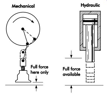
FIG. 4. The rated capacity of a mechanical press is available only at the
bottom of the stroke. The full force of a simple hydraulic press can be delivered
at any point in the stroke (Smith 1994).
Mechanical presses have the full rated force available only near the bottom of the stroke. The distance from the bottom of the stroke versus available force is determined by a force or tonnage curve. The force curves for six different mechanical presses are shown in FIG. 5.
In some cases, a sharper coined impression may be obtained at a rapid forming rate. Jewelry and medallion work makes use of both high-force hydraulic presses and drop hammers. Each pro cess has its own advantages. Often, die pressures in excess of 250,000 psi (1,724 MPa) occur in medallion work done on a hydraulic press.
A mechanical press with high force capacity often is larger than a hydraulic press of similar force capacity. Few mechanical presses have been built with force capacities of 6,000 tons (53.4 MN) or more. Higher tonnage and/or compact construction are practical in hydraulic presses.
Hydraulic presses for cold forging are built with up to 50,000 tons (445 MN) or greater force capacity. Some hydraulic fluid cell presses have force capacities over 150,000 tons (1,335 MN).
The pressure at which the press delivers full tonnage is important. The most common range is from 1,000-3,000 psi (6,894-20,684 kPa). Some machines operate at substantially higher pressures. There is no set rule on the best peak operating pressure for a press design. Obviously, higher pressures permit the use of more compact cylinders and smaller volumes of fluid. However, the pump, valves, seals, and piping are more costly because they must be designed to operate at higher pressure.
The force of a hydraulic press can be programmed in the same way that the movements of the press are preset. In simple presses, the relief valve system that provides overload protection may also serve to set the pressure adjustment.
This allows the press to be set to exert a maximum force that is less than the capacity of the press.
Usually, there is a practical lower limit, typically about 20% of press capacity. At extremely low percentages of force capacity, a stick-slip phenomenon known as stiction in the cylinder rod and piston packing can cause jerky, erratic action.
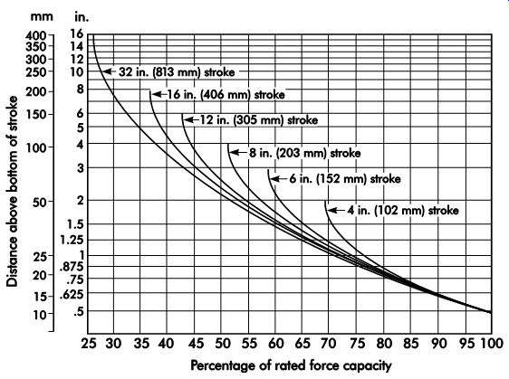
FIG. 5. Force curves for six different mechanical presses.
Press speeds
Most press users are accustomed to describing press speeds in terms of strokes per minute.
Speed is easily determined with a mechanical press. It is part of the machine specifications or can be measured with a stopwatch.
The number of strokes per minute made by a hydraulic press is determined by calculating a separate time for each phase of the ram stroke.
First, the rapid advance time is calculated. Next, the pressing time or work stroke is determined. If a dwell is used, that time is added. The return stroke time is added. Finally, the hydraulic-valve reaction-delay time is added to determine the total cycle time. These factors are calculated to determine theoretical production rates when evaluating a new process. In the case of jobs already in operation, measuring the cycle rate with a stopwatch is sufficient.
The forming speed and impact at the bottom of the stroke may produce different results in mechanical presses versus their hydraulic counterparts. Each material and operation to form it has an optimal forming rate. For example, drop hammers and some mechanical presses seem to do a better job on soft jewelry pieces and some jobs where coining is required.
In deep drawing, controllable hydraulic press velocity and full force throughout the stroke may produce better results. This is necessary to prevent shearing and tearing during the drawing process. Often, parts that cannot be formed on a mechanical press with existing tooling can be formed in a hydraulic press. Hydraulic presses can be provided with controllable force through out the press stroke and variable blank-holder pressure distribution.
Straight-side presses, such as the one illustrated in FIG. 6a, are much better able to withstand off-center loading and snap-through energy release than the type shown in FIG. 6b. Quality features in a press designed for severe work when ram tipping is to be minimized are a single-piston design together with a large ram or slide with long guiding and eight-point gibbing. However, loading should be carefully balanced and cutting dies timed to minimize snap-through shock to the best extent possible in any press-working operation.
Upgrading existing presses
Older presses are candidates to be upgraded for smoother, more reliable operation and reduced tooling wear. In some cases, rebuilding a damaged press can pay rapid dividends in reduced tooling repair costs and better part quality.
Electrical controls, which may no longer meet safety requirements, can be replaced. Usually, the most satisfactory way to retrofit a press is to install a new control package specially designed for the application. Such systems are available from several suppliers.
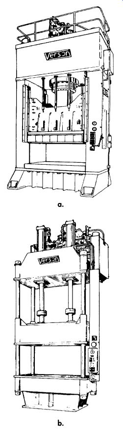
FIG. 6. (a) A straight-side hydraulic press is de signed for applications
requiring close alignment and high forces. This design will withstand moderate
lateral loads with little side deflection. (b) A two-cylinder, four post
hydraulic press is suited for light- to medium-duty work that does not involve
lateral (side) loads.
Die Cushions
When a single-action press is used for drawing operations, the manner in which the blank holder pressure is applied to control the flow of the metal blank is important. The application of pressure to a blank-holder is one of the features of a double-action press. Single-action presses lack this feature and, therefore, require supplementary blank-holding equipment.
Dies are sometimes built with a blank-holder using compression springs, air cylinders, or high-pressure nitrogen cylinders to supply the holding pressure. This greatly increases die cost. A press cushion can fulfill this requirement, lowering the cost of tooling.
Pneumatic Die Cushions
A pneumatic die cushion is supplied with shop air pressure. Normally, the design uses either one or two pistons and cylinders. The recommended capacity of a die cushion is about 15-20% of the rated press tonnage. The size of the press-bed opening limits the size, type, and capacity of the cushion.
FIG. 7 illustrates a pneumatic die cushion.
In this inverted type, the downward movement of the blank-holder, through pressure pins, forces the cylinder against a cushion of air inside the cylinder, and moves the air back into the surge tank (not shown). The external components, such as the surge tank, regulator, and pressure gage, are essentially identical in function to a press counterbalance system. On the upstroke, the air in the surge tank returns to the cylinder. Other designs function without surge tanks.
It is important to load the cushion evenly to avoid premature wear and cushion failure. The die designer should incorporate equalizing pins in the lower shoe if required to accomplish loading equalization. Often, these can be actuated by the upper heel blocks. In some cases, special pin drivers made of structural tubing may be attached to the slide to actuate equalizing pins.
Operator safety must be considered when per forming this operation because additional pinch points are created.
To avoid press and die problems, it is of extreme importance that the correct length of pins be used. In drawing and other critical operations, a pin that is just .060 in. (1.52 mm) longer than the others can easily cause a wrinkled or fractured part. When problems are encountered, and the pressure setting is found correct, the pins should be carefully measured with a micrometer or vernier caliper to determine if they are the same length. Further, the contact plate on the cushion and surfaces contacted by the tip ends of the pins in the die should be examined for wear.
Hydraulic Die Cushions
Hydraulic die cushions have the advantage of taking up less space than air cushions. Also, they can be equipped with fixed or servo-actuated relief valves. Programmable controllers and servo valves are used to control resistance throughout their travel. Hydraulic die cushions can be retrofitted to existing presses.
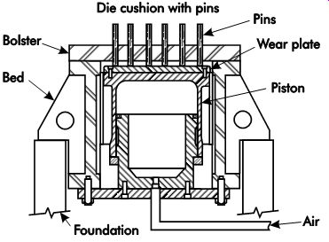
FIG. 7. Sectional view through a press bed and bolster illustrates a pneumatic
die cushion.
Hydraulic Forming Machines and Dies
One advantage of forming processes in which hydraulic pressure acts on one side of the work piece is that only one-half the die is needed. Simple dies may use rubber pads or cast shapes alone as a forming medium to transmit pressure.
The Guerin process uses a thick rubber pad contained within the ram of the press. The die is placed on the lower press platen or bed. This pro cess has long been used to form short runs of parts from thin, soft materials, such as aluminum.
Several processes apply hydraulic pressure to the workpiece through a flexible rubber bladder or membrane. These systems combine many of the advantages of direct fluid application with out the mess. The Wheelon forming process uses a method of applying direct hydraulic pressure to the rubber forming pad. The blanks are placed over simple male dies, similar to those used in the Guerin process. FIG. 8 illustrates a Wheelon hydraulic forming machine. The banks and dies are moved into the press frame on a carrier. Forming pressure is applied by hydraulically inflating a rubber bladder mounted in the immobile roof of the press. FIG. 9 shows a cross-section of the press frame with a die and blank in place. The rubber bladder is shown in the released (a) and forming (b) positions. This method is limited in depths of draw to about the same as the Guerin process. With pressures of 6,000-10,000 psi (41.4-68.9 MPa) available, practically all wrinkling is eliminated.
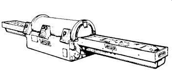
FIG. 8. The Verson Wheelon hydraulic forming machine.
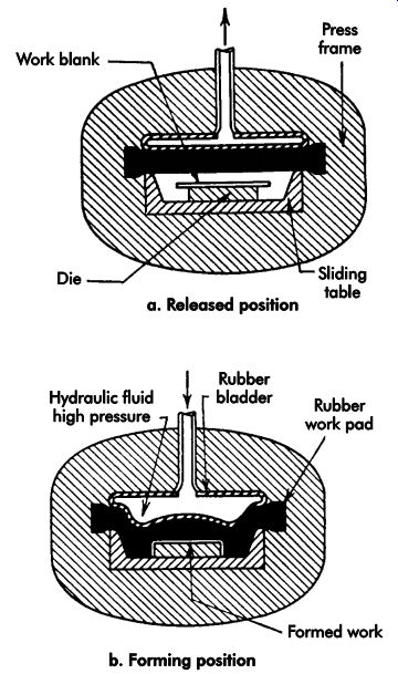
FIG. 9. The Wheelon forming sequence of operations.
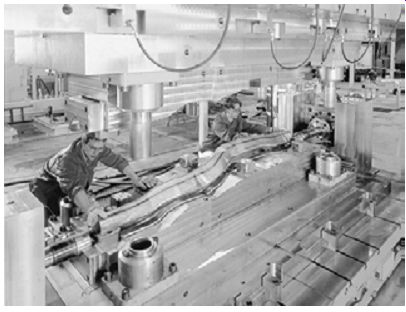
FIG. 10. Operators removing a formed frame member from a hydroforming die.
The axial plungers on either end of the die move into the tube upon die closure
and form a watertight seal.
Tubular Hydroforming
In the tubular hydroforming process, specialized press dies use oil or water under pressure to act directly on tubular workpieces. It is an old process that has found new uses, especially for automotive and truck-frame production. The tooling costs are low considering that complicated shapes can be produced in one or just a few steps.
To avoid housekeeping problems, water with a rust inhibitor is used instead of oil. FIG. 10 illustrates operators removing a formed frame member from a hydroforming die.
Hydroforming press design
Hydroforming presses nearly always use hydraulically actuated clamping. Typical clamping forces are from 700-5,000 tons (6,228-44,482 kN). Some presses employ a latching mechanism to hold the press in the closed position while forming pressure is applied to the inside of the tubes. Pressure applied inside the tubes to form them to the inside of die cavities is typically in the range of 5,000-45,000 psi (34.5-310.2 MPa). When the part is filled with fluid, a pressure intensifier may be used to economically achieve the high forming pressures required.
Multiple-stage hydroforming
FIG. 11 illustrates a multiple-stage hydro forming operation. By adding cams and other means of actuating forming and punching details, it is feasible to form complicated parts, including piercing holes. There is little fluid spillage, due to entering the punches while the part is pressurized and relieving the pressure before the punches are withdrawn.
Multiple-Slide Forming Machines
Slide forming machines originally were built to produce wireforms. Wire was fed into the ma chine, severed to length, and formed into the de sired configuration. From the initial dedicated machines evolved universal machines capable of producing a variety of wireforms simply by changing tooling.
Strip or ribbon stock is fed into the slide forming machine and processed the same as wire. To feed, cut off, and form, a conventional press is added to the machine as an integral member, and ribbon material can then be formed in a progressive die before the cut-off and forming sequence of the slide machine.
The four-slide machine, as it is commonly known, (more correctly called a multi-slide ma chine), was introduced to the metal stamping industry for processing parts that required more than could be achieved from conventional power presses and the progressive dies that complemented them.
If the cut-off slide, stripper slide, feed slide, and press slide are counted, the four-slide machine actually has more than four sliding members. It has four main driving shafts arranged in a rectangle where synchronous power is transmitted from one to the next by bevel gears at the corners.
The shafts carry cams of various configurations for various functions including four prominent cams, one on each shaft for forming; hence, the machine is labeled a "four slide." Later machine versions have included a provision for a sliding king post or mandrel and a twin front slide primarily utilizing one slide for blank-holding and the other for forming.
A bracket known as the king post-holder is fastened to the top platen of the machine and houses the king post plus the stripper shaft. The king post or forming mandrel, suspended from the king post-holder is the center of all forming activity. Single or multiple stages of forming are feasible with the stripper slide being used for transferring the blank from one stage to the next or ejecting the finished part through a large hole in the machine platen located directly under the king post. FIG. 12 is a plan view of a typical four-slide machine.
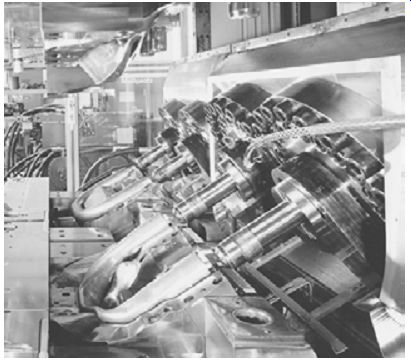
FIG. 11. A multiple-stage hydroforming operation used to make a "U"-shaped
tubular automotive suspension part.
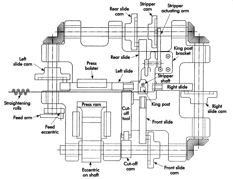
FIG. 12. Plan view of a typical four-slide machine looking down.
Further enhancements to four-slide machine versatility included multiple press attachments and the availability to reverse individual presses 180° to accommodate burr-side requirements or for forming or extruding in the press section toward the desired direction. Mechanical blank-holders also are a standard feature to facilitate tooling.
A vertical four-slide machine is essentially a horizontal four-slide machine tilted on edge. The press sections can no longer be reversed, but all slugs from gutting and piercing have gravity to assist their ejection. The king post or forming mandrel is relocated to the rear of the machine along with the stripper slide. The formed parts are now transferred and ejected forward toward the front of the machine rather than through the base platen. The major advantage of the vertical four-slide machine is convenience of tool setup as well as service and maintenance of the tooling in the machine. The need to bend over a machine to service tooling is eliminated and visibility improved due to vertical proximity and the relocation of the king post-holder to the face or rear of the platen.
The vertical, shaft-driven slide machine enables the addition of auxiliary slides for angular orientation toward the forming center of the machine.
The press section is located farther to the outside to permit added positioning and flexibility for the forming slides. The king post becomes the center mandrel and the number of motions available for transfer or ejection from the rear of the machine into the working area is increased.
The high-speed straight side press
FIG. 13 illustrates many key features of a modern high-speed straight-side press. The massive one-piece frame (1) is of cast-iron alloy construction. The mass and damping capacity of the frame is important to reduce the overall vibration level of the press.
A combination hydraulic clutch and spring-applied brake (2) provides rapid engagement and stopping. Achieving a reduced stopping angle at high speeds is a necessity if electronic tooling protection is to be effective. An automatic flywheel brake speeds up power lockout to permit rapid access for work in the die area.
Hydraulic preload applied to the slide adjusting screws removes all clearance (3). This feature eliminates thread play and wears during operation. A hydraulic cylinder at each connection sup plies pressure for hydraulic slide lockup.
The hydraulic system (4) lifts the slide to a fixed open position to provide access to the die for inspection, troubleshooting, and threading of stock.
The system returns the slide to the original shut height position against fixed mechanical stops.
Two large-diameter, hydrostatically guided pistons (5) provide slide alignment. Pressurized oil is supplied to these bearings as well as the large wrist-pin bearings. In addition, four hydro dynamic guideposts (6) are provided between the bed and slide at the material pass line level.
Motorized shut-height adjustment (7) is a standard feature. A mechanically driven shut-height indicator is provided to assist in making accurate shut-height settings.
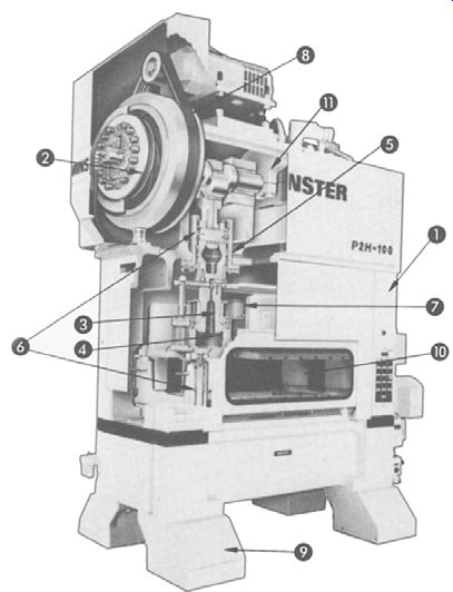
FIG. 13. Cut-away view showing the key features of a modern high-speed press.
The press drive motor (8) is equipped with an eddy current, variable speed drive. The motor is totally enclosed and fan cooled.
Press feet (9) can be factory equipped with integral press-shock mounts.
The press is designed to accept an integral lift-type sound enclosure (10) that is both mechanically and electrically interlocked. A counterweight (11) on the eccentric shaft provides dynamic balance.
The combination of an inherently vibration damping, one-piece frame, shock mounts, and acoustical enclosure on the press greatly reduce sound and vibration levels in the area. Other equipment may include quick die change bolster rollers and die clamps.
Transfer press and die Operations
Transfer presses have several distinguishing features that suit them for many types of medium- to high-volume work. Most operations use precut blanks, although there are combined operations. For example, the first station may be a coil-fed-blanking die.
Many different sizes of transfer presses are used.
The first type of transfer press, the eyelet machine, originally was designed to make small metal eye lets for shoes. Today, some small transfer presses are still called eyeleting machines, although great varieties of parts are produced on them.
Large transfer presses have force capacities of 3,500 tons (35 MN) or more. Transfer press operations have several common factors. These include:
• individual dies are used for each operation;
• reciprocating transfer-feed bars on each side of the press are fitted with fingers that move the parts between the dies, and
• feed bars are synchronized with the press ram's motion.
FIG. 14 illustrates a large specialized transfer press. The automotive and appliance industries are the principal users of this type of machine. All stamping operations required to complete large parts, such as automotive hoods and roof panels, are done in such presses. Flat blanks are destacked and automatically fed into the right end of the press. The transfer-feed-bar fingers move the parts from die to die. Completed stampings emerge from the left end, where they are placed in storage racks or conveyed to the assembly operation.
multiple-slide straight-side presses The straight-side press shown in FIG. 14 is an example of a highly specialized custom-built machine. The three slides and four columns are customized for the type of work to be performed.
Large, multiple-slide presses have a number of advantages, including:
• each slide can be designed to provide the required force, and
• by using multiple slides, ram tipping can be minimized.
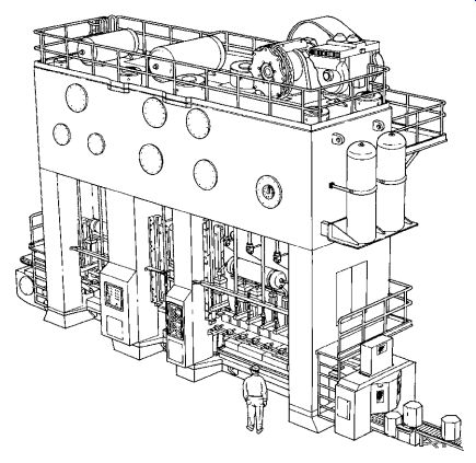
FIG. 14. A four-column, three-slide transfer press with a force capacity
of 46,000 tons (409 MN).
The center slide in FIG. 14 is designed for a heavy, single-station forming operation.
Placing a die having a high-force requirement, such as a stretch form or reforming operation, on one end of a long press slide can result in severe ram tipping, die damage, accelerated wear, and quality problems. This is often an unexpected problem in applications where large single- and double-slide transfer presses are specified.
The load on the slide should be balanced throughout the press stroke. This is an important consideration in the design shown in FIG. 14. Thus, when troubleshooting transfer-press problems, ram tipping sometimes is found to be the cause of poor quality work and excessive press and die wear. A solution may be to add a compensating load on the lightly loaded end of the slide.
Nitrogen cylinders with a force capacity and stroke equal to the draw-ring load on the opposite end of the slide springs may be required to provide the counterforce needed to balance the load.
Transfer Feed motion
Two types of transfer motion are used in transfer press operations. The simplest system uses dual-axis motion. Only in-and-out motion is used to grasp the part. The second axis of motion transfers the part from die to die.
FIG. 15 illustrates the motion of tri-axis transfer feeder bars for indexing parts between dies in a transfer press. In older designs, the transfer feeder bars are mechanically driven synchronously with the slide motion. The fingers, which are inserted into the transfer feeder bars, hold the parts during indexing. In some cases, the fingers use pneumatic jaw clamps to grasp the parts. Wherever possible, simple scoops that rely upon gravity are used.
The application of dual-axis transfer-feeder bar motion is limited to relatively flat parts with only shallow formed features. The lack of up-and-down motion results in the parts being dragged across the top of the lower die surfaces when transferred. The system works well within these limitations. The advantages, compared to a tri-axis system, are lower initial cost, less maintenance expense, and faster cycle times.
Tri-axis transfer is needed for parts having deeply formed features. Here, the part must be lifted out of the die cavity before being transferred to the next die.
Transfer Drive Methods
There are several basic systems for actuating transfer-feed motion. The original method, which is still in use, is to drive the transfer directly from the press crankshaft. Gears and cams transform rotary motion to the reciprocating action needed for part transfer.
Another mechanical drive system used for some new systems and retrofit applications uses plate cams attached to the press ram. The mechanism is driven by cam follower rollers.
Both pneumatic and hydraulic cylinder-driven systems are built into multistation dies. Many clever designs have been fabricated in press shops. Hydraulic systems are more costly but provide better control. The motions of pneumatic systems tend to require frequent adjustment because they are not as stable.
Most new transfer designs are powered by electrical servomotors-the best technology for most new designs. The technology includes a combination of a high-power servomotor, micro processor-based electronic control and solid-state power supplies. These are all mature technologies in widespread use in other industrial equipment, such as machine tools and robotics.
Equipment for De-coiling and Straightening Stock
Press auxiliary equipment includes stock de-coilers, straighteners, feeders, part handling and scrap removal devices, as well as robots and dedicated die change carts. Like any press-working equipment subject to movement, appropriate safeguarding measures are required to prevent injury to personnel.
A variety of commercially available coil handling, de-coiling, straightening, and feeding equipment is used in coil-fed die operations.
The equipment, available from many manufacturers, can be used interchangeably in a variety of configurations.
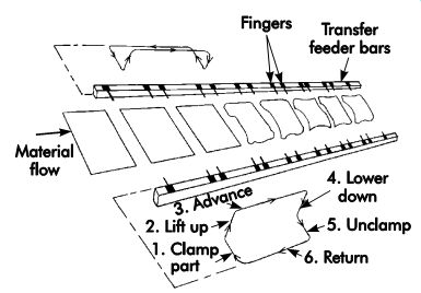
FIG. 15. Transfer feeder bars and fingers showing the motion sequence.
In some cases, the entire system is delivered as a turnkey package by the press builder or equipment supplier. However, it is common to find a mixture of used equipment working as an integrated system. Cost-conscious stampers often retrofit older equipment with modern drive systems and controls at a fraction of the cost of new machinery.
Quick Coil Change
A rapid means to band and remove a partial coil of stock left over from the job being removed is an important feature. Time is saved if the new coil is pre-staged at the de-coiler, as shown in FIG. 16. It is important to have the next coil ready.
During many production runs, quick coil change saves more time than quick die change.
Cradle-type de-coilers may be mounted on a movable track to center different widths of stock on the press centerline. In this case, markings of the correct settings should be provided to avoid trial-and-error adjustment.
Stock Feeders
There are many types and styles of stock feeders. Choosing between them is often dictated by affordability and what is already available in the press shop. The modern feeder of choice usually is the servomotor-driven roll feeder, although a crankshaft-driven roll feeder provides good service if correctly adjusted and maintained.
Air-driven hitch feeders are popular based on cost and ease of use.
An old but useful design for small work is the die- or press-mounted hitch or grip feed actuated by either the press ram or upper die shoe. This design is illustrated in FIG. 17. The operating cam fastens to the upper shoe. The remainder of the device attaches to the lower die shoe.
Provided the shut height of the die is set exactly the same each time, the feed pitch will always be correct. On the upstroke, the rollers at the left grip and move the stock a feed length determined by the adjustment nuts. Movement of the rollers, carried on a slide, is controlled by the spring. On the downstroke, stationary rollers at the right prevent backward movement of the stock. Both sets of rollers have one-way clutches so they can only turn in one direction.
CNC laser and turret punching machines
The need for building low-cost, short-run dies has been greatly lessened by the advent of the modern CNC punching and laser-cutting work cells. When these machines are used with nesting software, it is possible to produce several different parts from the same blank sheet of metal. Often, all of the stamping needed to make a product can be made quickly this way, greatly reducing inventory costs. A view of a combination laser and punching machine is illustrated in FIG. 18.
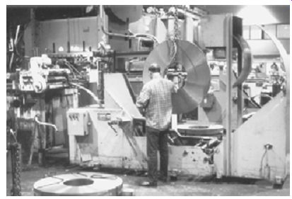
FIG. 16. An operator loads a coil into a powered de-coiling cradle. An overhead
crane is used to handle the coil safely. Note that a spare coil is ready
at the decoiler.
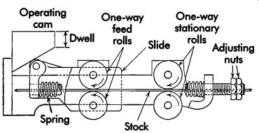
FIG. 17. A die- or press-mounted roller-type grip feeder.
Turret punching machines started to appear in sheet-metal shops doing aircraft work decades ago. These machines were simple, hand-actuated punches with the upper and lower turrets rotated in alignment by a simple gear or roller chain and backshaft arrangement. These evolved to power-actuated machines capable of both cutting standard holes and nibbling out special shapes.
Some of the turret punch-holders bend and form features such as louvers and bent tabs. FIG. 19 illustrates a machine with that capability.
FIG. 20 shows a part being discharged from a machine by a tilting worktable. For cutting steel, oxygen is the usual assist gas. Stainless steels also can be cut. Here, argon and/or nitrogen are used to obtain the smoothest cut edges.
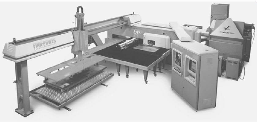
FIG. 18. A machine with both punching and laser-cutting capability, which
is useful for fast production of small lots of parts.
FIG. 19. An example of a combined CNC laser and turret punching machine
equipped for forming louvers and other features.
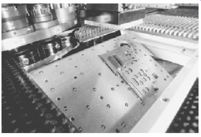
FIG. 20. A finished part is being discharged. A wide variety of different
parts can be made from a single sheet of metal using the combined cutting
capability of a CNC laser and turret punching.
A Punch-setting Breakthrough
At one time, low-cost dies used punches set in low-melting-temperature alloys. Today, it is common to set punches that run with zero clearance.
They are used for cutting materials, such as rubber and mica in filled epoxy cement, and aided by a retaining screw. This simple construction method can provide dies of high precision at a much lower cost since a precision jig, ground punch-holder is not required. Ways of reducing tooling costs are limited only by human imagination.
Economic payback
Laser CNC cutting and punching represents a large capital investment for many shops. Calculating a reasonable payback period is important.
Such a machine can eliminate many short-run dies and several presses, freeing up valuable floor space. If the cost of ownership and rate of machine utilization represents a good return on investment with machine time to spare, this time can be marketed to take on new product lines or produce short-run parts for other clients.
Forging
While forging may seem like an obsolete pro cess to the public not involved in an industrial manufacturing base, it remains the best way to produce a strong part that can sustain the high stresses of many critical applications. Forging is used to produce aircraft engines, power turbines for electrical power generation, high-quality engine crankshafts, and connecting rods and axle shafts, which are upset on one end to produce a hub to which the driving wheels are fastened. The first net-shape methods of manufacturing metal parts were achieved by forging, and it remains the most common method without wasted material.
Powdered metal Compaction
Many parts are made by compacting powdered metal into a near-net-shape form with slight porosity. To achieve a stronger part, that metal compaction can be heated to a welding temperature in an oven with a carefully controlled atmosphere to permit the fusion of metal particles in a process called sintering. Next, the hot powdered metal compactions are struck in a forging die to close all voids. This method is popular for producing extremely strong connecting rods and automotive engine uniformity.
Nonferrous Forgings
The largest nonferrous forgings made in great quantities are aluminum semi-truck and tractor wheels. These wheels are cold forged using a 50,000-ton (445-MN) hydraulic press. Although the wheels are costly to make, the weight savings compared with steel wheels pays back the cost difference in additional payload capacity.
Solid brass ornamental hardware often is forged to produce a net-shape or near-net-shape part. Such forgings are economical to make and yield better parts than casting. Reject rates are low and the polishing process is simplified.
The aerospace industry has many essential applications for aluminum and titanium alloy forgings, such as landing gear and many other critical structural applications.
Forging Hammers
The earliest forgings were the work of a black smith's hammer. This was mechanized several centuries ago as the gravity drop hammer was invented. The drop hammer blow is controllable by the height to which the hammer is lifted. A well-equipped, gravity drop-hammer shop has hammers ranging from 1,000-5,000 lb (454-2,268 kg). One advantage of drop-hammer presses is that excellent repeatability is achieved by the height to which the hammer is lifted and number of blows delivered. For critical applications, the operator's skill is augmented by equipping the drop hammer with CNC controls to ensure repeatability from part to part.
Screw-type Forging presses
FIG. 21 illustrates a 900-ton (8-MN) screw-type forging press. These presses evolved from the manual screw presses that are still found in tool rooms for testing dies and light pressing applications. The screw is actuated by a flywheel that is brought up to operating speed by a motor. When the flywheel engages the screw, all of the kinetic energy of the flywheel is delivered to the workpiece. Thus, a limited amount of energy is available to do the work without repeating the cycle. One disadvantage to a screw press in hot forging work is that a finite amount of time is required to reverse the flywheel. This delay enables the heat in the work to transfer to the die, which not only cools the work but also may overheat the die in repetitive work.
Crankshaft
Forging presses Forging presses operated with crankshafts, clutches, flywheels, and brakes differ little, if any, from conventional mechanical stamping presses. Typically, they are more compact and robust than their conventional metal-stamping counterparts.
One danger to be aware of is that, unlike drop hammers and screw presses, which have a finite fixed amount of kinetic energy to deliver to the workpiece in the die, a crankshaft press can de liver many times more energy if overloaded by a double hit or misalignment accident. Such an accident can fracture the die, sending shrapnel at high velocity into the pressroom. The machine may require heavy bulletproof plastic or metal guarding to address this hazard.
Hydraulic Forging Presses
Hydraulic presses are used for open-die and closed-die forging, such as the example mentioned previously of the 50,000-ton (445 MN) hydraulic press used to force an aluminum blank into a die to produce semi-truck wheels. While few hydraulic forging presses are built over the 50,000-ton (445-MN) capacity, they are used al most universally in force capacities of 2,000 tons (18 MN) and higher.
Forging dies
Forging dies are made of especially tough grades of hot-work tool steel machined in the hardened state. Because of the high forces involved, computer-aided design (CAD) programs that calculate and illustrate stress distribution under forging conditions are especially useful for designing robust dies without making them larger than necessary.
Dies subjected to extremely high forces are often reinforced with one or more shrink rings that form an interference fit around the die. These are shrunk into place by heating, hence the term "shrink ring." High forces are achieved in forging jewelry items with high detail, as well as the back extrusion of steel artillery ammunition casings.
The subject of forging die design is a fascinating area of work but beyond the scope of this guide.
References
Smith, D. 2001. Die Maintenance Handbook. Dear born, MI: Society of Manufacturing Engineers.
--. 1994. Fundamentals of Pressworking. Dearborn, MI: Society of Manufacturing Engineers.
Smith, D., ed.1990. Die Design Handbook, Third Edition. Dearborn, MI: Society of Manufacturing
Other Refs.
The Society of Manufacturing Engineers (SME) has developed the Fundamentals of Tool Design video series, which comprises nine DVDs, of which two relate directly to this section's content: Progressive Die Design (18 minutes), and Troubleshooting Tool and Die Making (20 minutes).
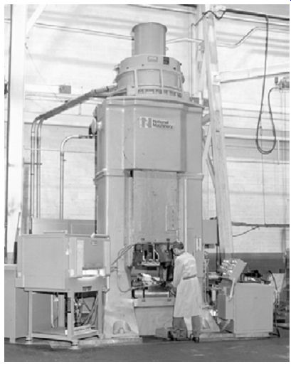
FIG. 21. A 900-ton (8-MN) screw press.
Progressive dies perform fundamental cutting and forming operations simultaneously at various stations within a die during each press stroke.
The Progressive Die Design program explores the design variables used in part/strip development that contribute to part quality, progressive die tool maintenance, tool life, and tool cost, including part orientation, part transport, stock positioning, and the number of progressions.
Also examined is the effective use of lubricants in progressive dies to control friction, extend tool life, and improve part surface quality.
The Troubleshooting Tool and Die Making program examines the many issues that may arise in the tool and die making process, explaining possible causes and providing suggestions to troubleshoot problems. Some of the industries and processes explored include stamping, forging, extrusion, powder metallurgy, and injection molding.
Engineers.
QUIZ
1. What force systems are used in power presses?
2. What are the types of gap-frame presses?
3. What are the advantages and disadvantages of a gap-frame press as compared to a straight-side press?
4. What are the principal contrasts between mechanical versus hydraulic presses?
5. What are three major considerations made during power press selection?
6. What is the most satisfactory way to upgrade (retrofit) an older press?
7. What are the most useful types of die cushions?
8. Which forming process is especially suit able for short runs of parts from thin, soft materials such as aluminum?
9. What are the two principal advantages of the hydroforming process?
10. What are the distinguishing features of transfer press/die operations?
11. What technological advancement has reduced the need for building low-cost, short run dies?
12. What process remains the best way to pro duce a strong part that can sustain the high stresses required of aircraft engines, engine crankshafts, etc.?