Fixtures are workholders designed to hold, locate, and support a workpiece during the machining cycle. Unlike jigs, fixtures do not guide the cutting tool, but they provide a means to Reference and align the cutting tool to the workpiece. Fixtures normally are classified by the machine with which they are designed to be used. Sometimes a sub-classification is added to further specify the fixture classification. This sub-classification identifies the specific type of machining operation the fixture is intended to perform. For example, a fixture used with a milling machine is called a milling fixture; however, if the operation it is to perform is gang milling, it also may be called a gang-milling fixture. Likewise, a band-sawing fixture designed for slotting operations may be referred to as a bandsaw-slotting fixture.
The similarity between jigs and fixtures normally ends with the design of the tool body. For the most part, fixtures are designed to withstand much greater stresses and tool forces than jigs, and should always be securely clamped to the machine. For these reasons, the designer must be aware of proper locating, supporting, and clamping methods when fixturing any part.
General Considerations
Cost, production capabilities, production process, part, and tool longevity are some of the general considerations that must share attention with the workpiece when a fixture is designed.
This section provides an explanation of these elements, which must be addressed and modified for the particular workpiece or production situation to ensure a successful fixture design.
While each design consideration is treated separately in practice, all are usually considered simultaneously in fixture design. So, the designer must determine the effects a design decision may have on the complete, overall function and operation of the tool. Changes to a fixture design are much easier and less expensive to make while the tool is still on paper. They are very expensive when they must be made during production or after the tool is built.
Fixture Cost
As with all tooling, the first consideration in fix ture design is the cost versus the benefit. The production quantity, rate, or accuracy must warrant the added expense of special tooling. In addition, a fixture must pay for itself with savings derived from its use in as short a time as possible.
Once the decision is made that a fixture is required, the part print, process specifications, and other production documents are studied to determine the best and least expensive type of tool. Details such as locating and supporting the part, clamping, and tool referencing must all be considered in the initial design.
The tool designer should know enough of economics to determine the relative cost/benefit relationship of any tool design. Whether temporary or permanent tooling should be used and just how much money should be requested for a workholder are decisions the designer weighs to get a realistic picture of production costs.
Not only is a tool designer expected to prepare accurate cost estimates, but these estimates and the decisions behind them also must be completely defensible to management.
Production Capabilities
The machine tool specified for a machining operation should be examined. Every detail that might affect the mounting and operation of the fixture must be addressed. Table sizes, table travel on all axes, spindle size and movement, spindle swing, distance between centers, and workholder mounting methods are typical examples of points the designer must consider before beginning a fixture design.
A major consideration is the condition of the workpiece to be held by the proposed work holder for the next operation to be performed.
This includes the physical characteristics of the workpiece (that is, whether it is round, irregular, large, heavy, of weak or strong sections, etc.). The operation to be performed and the physical characteristics will dictate whether the workpiece must remain stationary or move along a definite path relative to the cutting tool. Machine tools produce the needed motions for the workpiece and the cutting tools. Most of these motions are straight-line or rotary, or combinations of both.
Some operations appear to produce an irregular path for the cutting tool on the workpiece. This seemingly irregular path is often the result of the combination of several straight-line and rotary motions. Except for speed consideration and the degree of obtainable simplicity, only the relative motion of the cutting tool to the workpiece is of importance. For instance, the turning of flanges on a valve body or a flanged-T-pipe fitting could be performed with either the workpiece or the tool revolving (see FIG. 1).
Whether the workpiece or cutting tool moves in a straight line, revolves, or moves in some combination of both, the design requires careful coordination of the workholder to the workpiece and the workholder to the machine tool. Operations in which the workpiece revolves require great care in the attachment of the work holder to the machine tool and the means of actuation of the workholder. Unbalanced masses in the workholder and the workpiece must be minimized by proper balancing. This is particularly true in high-speed applications, such as turning with tungsten carbide, cermet, ceramic, cubic-boron nitride (CBN), and diamond cutting tools.
The weight and size of a workpiece influence the type and size of machine tool used for a particular operation. The combined weight of the workholder and part must be carefully matched to the capacity of the ways, bed, table, and spindles of the machine tools. Excessive weight may cause distortion in the machine tool, safety concerns, and inaccurate work.
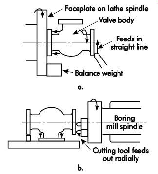
FIG. 1. Machining a valve body by either (a) work piece rotation or (b)
tool rotation.
In cases where the specified machine is not the best choice, or where the machine cannot perform the required operation, the designer should consult the process engineer to determine if another machine tool can be used. While it is good practice to fully utilize a machine's capabilities, overloading a small machine tool is not efficient. Often, money can be saved by using a larger machine tool. Running a small machine to its maximum limits or capabilities over a long production run will not only shorten the life expectancy of the machine tool, but it also may not produce the degree of precision required in the part. If there is any question as to the estimated power required for a job and the available power in the machine tool, the designer or process engineer should select the machine with more power available than that required for the operation. Before any fixture design is finalized, the designer must make sure the machine tool will accommodate the fixture in every respect.
When designing a fixture, the cutting tool is another factor that must be carefully evaluated.
As with jigs, cutters specified for fixtures should, whenever possible, be of standard, off-the-shelf sizes. Designing a special cutter when a standard cutter would work is very costly. Even if the standard cutter requires a slight modification of the fixture, the benefits and savings derived over the life of the fixture would more than pay for the additional design time.
Production Process
The tool designer and process engineer should work together to determine the best method to produce the part. The optimum situation in fixturing is where the part can be clamped one time and not removed from the fixture until it is completely machined. This reduces costly part handling and minimizes the chance of errors when switching the part from one fixture to another. In cases where the part must be removed from the fixture, the tool designer and process engineer should find methods to process the part that require the least number of fixture changes. When more than one machine is required, consider moving the fixture and part from machine to machine.
To achieve the lowest cost per part in production, the fixture must be fast operating, easy to load and unload, and have a positive, foolproof method of locating the part. In addition, when the volume of production permits more money to be spent, semi-automatic or automatic tooling should be considered. As the volume of production increases, the opportunity to save more per part increases dramatically. Multi-part machining and power clamping are other areas that could be explored to reduce the cost per part in production.
On all operations, the magnitude and direction of the forces produced by the material-removing operation determine the necessary holding forces. Cutting forces must be held within limits so the part cannot be distorted to an amount that would affect the required accuracy. Rigidity and strength of the workpiece limit the applicable holding forces and the speed and amount of metal removal per unit of time. A thin-walled part may not be able to sustain heavy cutting and holding forces without distortion or damage.
The mounting or attachment of the workholder or the workpiece to the machine tool should be arranged so the forces produced in the material removing operation are absorbed by the strongest and most rigid parts of the machine tool. Cut ting forces should tend to hold the workholder against the bed of the machine rather than lift it away. Projection should be minimized between the point at which the cutting force is applied and the nearest support. Cutting forces that act parallel to the bed, table, and faceplate should be applied as close to the bed as possible. Further, cutting forces should never be permitted the ad vantage of a large lever arm that could increase the tendency to loosen or pry away the workpiece and the workholder from their attachments. This is in contrast to holding forces, where the effect of a large lever arm or mechanical advantage is always desirable.
FIG. 2 illustrates a lathe chuck and a short workpiece to be turned. The cut is relatively close to the supporting spindle bearing and no difficulty is expected. Increasing the workpiece length, however, will give the cutting tool greater leverage; higher side thrust will be produced, which may cause difficulties in the spindle bearing. The workpiece will deflect much more if the same size chip is removed as on the short piece.
The results may be inefficient material removal, tool chatter, low accuracy, and poor tool life.
Part
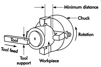
FIG. 2. Minimizing cutting force by applying holding force as near as possible
to the point of tool application.
In conjunction with general, machine, and pro cess considerations, the part also must be a major factor in the design of a fixture. All relevant details, such as location and clamping surfaces, clamping methods, areas requiring machining,
the amount of machining required, and the degree of surface finish desired all must be considered in the initial phase of fixture design.
Types of Fixtures
Fixtures are classified either by the machine they are used on, or by the process they perform on a particular machine tool. However, fixtures also may be identified by their basic construction features. For example, a lathe fixture made to turn radii is classified as a lathe-radius turning fixture.
But if this same fixture had a simple plate with a variety of locators and clamps mounted on a face plate, it also could be considered a plate fixture. Like jigs, fixtures are made in a variety of forms.
While many fixtures use a combination of different features, almost all can be divided into five distinct groups. These include plate fixtures, angle-plate fixtures, vise-jaw fixtures, indexing fixtures, and multi-part or multi-station fixtures.
Plate Fixtures
Plate fixtures, as their name implies, are constructed from a plate with a variety of locators, supports, and clamps (FIG. 3). They are the most common type. Their versatility makes them adaptable for a wide range of different machine tools.
Plate fixtures may be made from any number of different materials, depending on the application of the fixture. For example, if a large fixture is needed, and it is only required to make a few parts, aluminum or magnesium plate may be selected to keep the weight of the fixture to a minimum. If, however, weight is not a factor and a large number of parts must be made, another material such as tool steel may be selected.
Likewise, if the part or process requires a material resistant to corrosion, a nickel-based alloy might be selected. But, as is usually the case, a combination of different materials may be used to construct the plate fixture. The part being machined and the process being performed are the only guides the tool designer has when selecting material.
Angle-plate Fixtures
The angle-plate fixture in FIG. 4 is a modified form of plate fixture. Here, rather than having a Reference surface parallel to the mounting surface, the angle-plate fixture has a Reference surface perpendicular to its mounting surface. This construction is useful for machining operations performed perpendicular to the primary Reference surface of the fixture.
Another variation of the basic angle-plate fix ture is the modified angle-plate fixture (FIG. 5). This design differs from the basic angle plate in that where the angle plate fixture is designed to be at a 90° angle to its mounting surface, the modified angle plate is made to accommodate angles other than 90°.
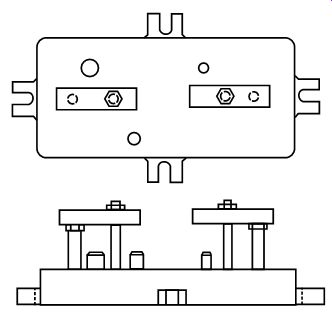
FIG. 3. Plate fixtures.
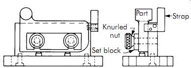
FIG. 4. Angle-plate fixture.
Vise-jaw Fixtures
Vise-jaw fixtures are basically modified vise jaw inserts machined to suit a particular work piece. In use, modified vise jaws are installed in place of the standard, hardened jaws normally furnished with milling-machine vises. Vise-jaw fixtures are the least expensive type of fixture to produce, and since there are so few parts involved, they are also the simplest to modify.
FIG. 6 shows several examples of parts easily fixtured with this type of workholder.
The principal advantage of using a vise-jaw fix ture is that only the locating elements need to be constructed to suit each part. The milling-machine vise contains the clamping elements and the means to attach the fixture to the machine table. If simple or compound angles need to be machined, a vise with these capabilities may be used. The only limitations to using this type of fixture are the size of the part and the capacities of the available vises.
Indexing Fixtures
Indexing fixtures (FIG. 7), like indexing jigs, are used to Reference workpieces that must have machine details located at prescribed spacings. The typical indexing fixture will normally divide a part into any number of equal spacings, such as those used for geometric shapes or gears.
Some may be used to locate and Reference a workpiece for unequal spacings. Regardless of the configuration of the workpiece, indexing fixtures must have a positive means to accurately locate and maintain the indexed position. The most common device used for location and indexing is a simple indexing pin, as shown in FIG. 7.
Multipart Fixtures
Multipart or multistation fixtures (FIG. 8) are normally used for one of two purposes: to machine multiple parts in a single setting or machine individual parts in sequence, performing different operations at each station.
Fixture Classifications
As previously mentioned, fixtures are normally classified by the machine tool with which they are designed to be used. The following sections provide a brief description of each of the major fixture classifications and their basic design characteristics.
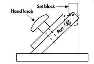
FIG. 5. Modified angle-plate fixture.
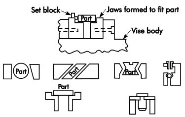
FIG. 6. Vise-jaw fixture.
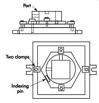
FIG. 7. Indexing fixtures.
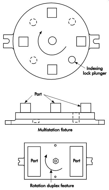
FIG. 8. Multipart or multistation fixture.
Milling Fixtures
Milling fixtures are the most common type of fixture in use. The simplest type of milling fixture is a milling vise mounted on the machine table.
However, as the workpiece size, shape, or complexity becomes more sophisticated, so does the fixture. Following are a few points to be considered when designing fixtures for milling operations.
• The design should permit as many surfaces of the part to be machined as possible, with out removing the part.
• Whenever possible, the tool should be changed to suit the part. Moving the part to accommodate one cutter for several operations is not as accurate or efficient as changing cutters.
• Locators must be designed to resist all tool forces and thrusts. Clamps should not be used to resist tool forces.
• Clearance space or sufficient room must be allotted to provide adequate space to change cutters or load and unload the part.
• Milling fixtures should be designed and built with a low profile to prevent unnecessary twisting or springing while in operation.
• The entire workpiece must be located within the fixture's area. In cases where it is either impossible or impractical, additional sup ports or jacks must be provided.
• Chip removal and coolant drainage must be considered when designing the fixture.
Sufficient space should be allotted to easily remove chips with a brush.
• Set blocks or cutter-setting gages must be provided in the fixture design to aid the operator in properly setting up the tool in production.
Lathe Fixtures
The same basic principles that apply to the design of milling fixtures also apply when de signing lathe (turning) fixtures. The only major difference between the two is the relationship between the workpiece and the cutting tool. In milling, the workpiece is stationary and the cutting tool revolves. However, with turning operations, the workpiece revolves and the cutting tool is stationary. This situation creates another condition the tool designer must deal with-centrifugal force. The complete fixture must be designed and constructed to resist the effects of the rotational, or centrifugal, forces present in turning.
Lathe fixtures are typically fastened to the faceplate via machine screws and T-bolts. Initial location is established by using a counterbore in the lathe faceplate, which receives a fixture back-plug. The relationship is used to maintain the lathe-spindle centerline.
The least expensive type of lathe fixture is the standard lathe chuck (three or four jaws) with special jaws or inserts machined to fit the part.
Three-jaw chucks are normally used for holding round or hexagonal stock. The jaws can be either internal or external and move simultaneously.
Four-jaw chucks can have either internal or external jaws that move independently. Odd-shaped workpieces are best located and held in a four-jaw independent chuck.
Following are a few basic design characteristics that apply to lathe fixtures.
• Because they are designed to rotate, lathe chucks should be as lightweight as possible.
• While perfect balance is not normally required for slow-speed turning operations, high rotational speeds require the lathe fixture to be well balanced. There must be dynamic balance about the rotational center line as vibrations cause tolerance variation.
In most fixtures, balance is achieved by using counterweights positioned opposite the heaviest part (or area) of the workpiece.
• Projections and sharp corners should be avoided, since these areas will become al most invisible as the tool rotates, thus they could cause serious injury.
• Whenever possible, parts to be fixtured should be gripped by their largest diameter or cross-section to overcome rotating torsional forces.
• The part should be positioned in the fixture so that most of the machining operation can be performed in the first fixturing. It should be located from small critical surfaces, which need to be kept clean.
• Clamps should be positioned on rigid surfaces or areas before and after machining.
Clamping over an area to be bored to a thin wall thickness could cause the part to warp or deform, thus causing the hole to be bored incorrectly.
• Clamps must not come loose from centrifugal force produced during the machining operation.
• As with other fixtures, some means of cutter setting should be incorporated into the design. However, since the workholder will be rotating, this setting device should be removed prior to machining.
• Whenever possible, standard lathe accessories should be adapted to the design of turning fixtures. For example, lathe faceplates are an ideal method to mount large fixtures.
Similarly, standard lathe chucks or collets can be modified for application in many fixturing applications. The loading and unloading time can be facilitated by ejectors.
Grinding Fixtures
Grinding fixtures are a family of fixtures rather than a single classification. The major types are surface grinding fixtures and cylindrical grinding fixtures.
Surface grinding fixtures have the following design characteristics.
• Although similar in design to milling fixtures, surface grinding fixtures are made to much closer tolerances.
• Whenever practical, magnetic chucks are used to hold the workpiece. In these cases, the fixture is simply a device to contain the workpiece and prevent its lateral or trans verse movement.
• Adequate room or slots are specified to permit the escape of coolant and easy removal of built-up grinding sludge.
• Coolant containment devices or splash guards are provided to keep the fixture from spilling coolant on the floor around the machine.
• Fixture elements in contact with the magnetic chuck should be made from ferrous materials if they are to be held on the chuck.
If they are not to be held to the chuck, then a nonferrous metal should be specified.
• If not built into the machine, provisions are included for rapid wheel dressing and truing in the design of the fixture.
• All locators are accurately and positively positioned.
Cylindrical grinding fixtures have the following design characteristics.
• Cylindrical grinding fixtures often are similar to lathe fixtures.
• Since cylindrical grinding is normally a secondary operation, performed after turning, it is often desirable to use the same center holes for grinding as for turning the part.
• Coolant buildup is seldom a problem with cylindrical grinding; however, sludge removal must be addressed.
• The fixtures should always be perfectly balanced to achieve the desired results.
• When possible, standard accessories and attachments are used. These include grinding collets, chucks, and drive plates with special right-angled holders called "dogs."
• Provisions for wheel dressing and truing are incorporated into the fixture design.
Boring Fixtures
Boring fixtures are designed to hold the work piece while the part is bored. These fixtures differ from boring jigs in that they do not have any provision for guiding or supporting the boring bar. Boring fixtures are normally used for large parts with large holes where the boring bar is rigid enough to provide additional support. A pilot bushing is not needed.
Boring fixtures, like milling fixtures, should have some provision for setting the position of the cutting tool relative to the part. In cases where a boring fixture is to be used on a large machine, such as a boring mill or vertical turret lathe, it is also good practice to include alignment areas on the fixture to ensure proper alignment with the machine.
Broaching Fixtures
Broaching fixtures are designed to simply hold and locate a part relative to either an internal or external broach. Since there is a great deal of cut ting force exerted during broaching, the complete fixture must be built more substantially than those for other processes.
Internal broaching fixtures need only locate and hold the part in proper position relative to the hole in the broaching machine. Most broaching is of the pull type and tends to keep the part firmly seated on the fixture. However, clamping devices are necessary to establish the proper relationship and maintain the position of the part until the broaching pressure pulls the part against the table.
External, or surface broaching, requires a different approach to fixturing. Since this type of broaching is performed on the outside of a part, the fixture must be designed to resist both pulling and perpendicular thrust that tends to try to push the part away from the broach. In either case, the principal purpose for a broaching fixture is to maintain the proper relationship between the part and the cutting tool, and to prevent the part from moving.
Sawing Fixtures
Two primary machines commonly used for sawing operations are the vertical bandsaw and the horizontal bandsaw. With both types of machines, the main intent is to accurately position and hold the workpiece so it can be either sawed into pieces or slotted with the saw blade. The following are a few design characteristics peculiar to these sawing fixtures and the sawing process in general.
• When possible, standard saw accessories and attachments should be used in conjunction with fixturing elements.
• Clamps, locators, supports, or similar fixture details must be kept clear of the blade path.
Since the area occupied by the saw blade on both types of bandsaws extends above and below the actual working area, any over hanging fixture elements could interfere with normal operation of the saw.
• Provisions for coolant drainage and chip disposal must be planned into the fixture design. While most bandsaws have an internal chip disposal system, a significant amount of chips also will collect in the fix ture unless some means for their elimination is planned.
• When practical, table slots should be used to Reference the fixture to the saw blade.
• Use power feed whenever possible. This may require designing a means to secure the power-feed chain to the fixture.
Standard Fixture Mounting
Quite often, only standard accessories such as clamps, straps, T-slot bolts, T-slot nuts, and jacks are needed to hold a workpiece. This is especially true where only a few pieces have to be produced and economic considerations do not justify more elaborate workholders. Most machine tools can accommodate such equipment. The beds and tables of machine tools, such as drill presses, boring mills, and jig bores, have T-slots milled into their worktables. Various types of workholders, chucks, arbors, and collets may be attached to the spindles of machine tools, such as lathes and grinders, either directly or with adapters. There are standards for the sizes and spacing of T-slots on tables, beds, and other equipment to which workholders are to be attached. Standards for spindles are established as well. Adherence to standards can result in economic interchangeability and multiple sources of tooling. Tool costs will be lower because the supplier can more economically produce standard components in larger quantities.
Always be sure the fixture can be solidly located on the machine. A fixture that rocks or that cannot be kept from twisting under cutting forces will not provide acceptable accuracy.
Relationship Between Fixture and Cutting tool
The direction and magnitude of forces created at the cutting tool-workpiece interface must be known. Use this knowledge to minimize the size of force moments (force × distance of force application) by reducing the moment arm. Avoid excessive projection, and provide additional sup ports where needed.
The relative motions between the workpiece and the cutting tool may change the tool geometry during the cutting cycle. Rake and clearance angles may change from a selected optimum condition to a bad condition.
The final objective of every material-removing operation is the removal of a certain amount of material per unit of time, to a certain depth, thickness, diameter, contour, and other related specifications. These quantities can be obtained by controlling machine motions with stops, gages, or computer controls. Workholders may be equipped with stop surfaces such as the top of a drill bushing against which a drill stop abuts. Gages may be placed between a milling cutter and a Reference plane setup block on a workholder to obtain the right thickness of a workpiece after milling (FIG. 9). Swing stops on lathe fixtures and arbors may be used to locate workpieces for removing stock evenly from both sides (FIG. 10).
It is necessary to check for and control the interference between any cutting edge of the cut ting tool and any part of the workholder during possible contact of workholder and cutting tool.
Thus it is advisable to simultaneously check for, minimize, and control excessive nonproductive approaches of cutting tools to the workpiece.
Planning should be done to avoid "cutting air." Space must be provided to remove and load workpieces easily, without danger to the operator or damage to the workpiece and equipment. In addition, space is required to insert and remove cutting tools, especially with automatic tool changers. This includes space for the application of any wrenches, keys, or other tools used to change cutting tools. Such change should be possible without removing the workpiece.
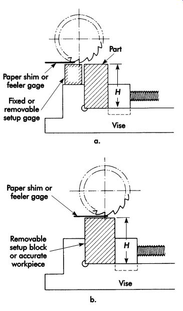
FIG. 9. Use of a gage block in setting up a milling operation.
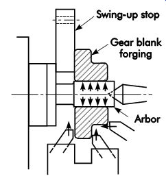
FIG. 10. Lathe fixture with swing stop.
Tool Positioning
Tool positioning refers specifically to locating the tool with respect to the work, or vice versa.
Prior to setting up a workpiece, the blueprint and workpiece are studied to determine primary and secondary locating points or surfaces.
Once these are determined, it is then necessary to visualize how these points or surfaces may be accurately located in relation to the locating means.
Relationship to Locators
Locators comprise the alignment or gaging surfaces of any angle, plate, bar, V-block, vise, or the like, which are secured to or part of the worktable or fixture. A T-slot may be considered a locating means, but generally such slots are only accurate enough for rough machining. Locators are used to properly position the work relative to the tool (see FIG. 11).
Keys are used under the base of an angle plate, vise, or workholding fixture. They provide an easy and accurate method of aligning a work holding fixture to a T-slot with the same degree of accuracy as the T-slot itself. Before using the T-slots as a basic locating Reference, their ac curacy should be established in relation to the movement of the table or cutter. For lengthwise or crosswise mounting, removable keys are used extensively, especially in vises with slots at right angles to each other. Both the key and the T-slots should be periodically inspected for wear to en sure proper dimensions and accuracy between the key and locating means.
The most practical procedure for establishing the relationship of the tool to the work will be governed by the type and size of the machine, type and size of work, production rate, and specified dimensions and tolerances of the cut.
Correct tool-positioning results in proper depth and location of the finished cut. Regardless of the type of machine involved, there are several different techniques for locating the work in relation to the tool. The exact technique is determined by the specific job requirement. Mass production may dictate a great expenditure of money to minimize the time required for locating parts, compared with less expenditure and more time for locating a single part.
Cutter-setting devices
Gage or setup blocks are a common means of Reference for cutter setting (FIG. 12). In many cases, the Reference may be a designated surface on a locator (locating means). In its correct position, the cutter should clear the setting surface by at least .03 in. (0.8 mm). Usual shop practice employs only one feeler thickness to avoid use of the wrong size on any particular operation. The thickness of the feeler should be stamped on the fixture base near the setup block.
Optimal methods are used extensively for gaging the accuracy of tool position in relation to the work and locating means. The many optical tooling equipment designs make broad applications in tool-to-work locations possible. One typical application is the establishment of an exact drill-center location. An optical instrument is inserted in the chuck. Through high magnification, the eyepiece and cross-hairs are used to determine the exact center. The work is clamped securely to the locating means and rechecked for proper tool-center alignment. The optical instrument is then removed from the chuck and replaced with the drill. The same principle may be applied for gaging the indexing accuracy of a rotary fixture or index plate onto which work is positioned for machining.
Design Fundamentals
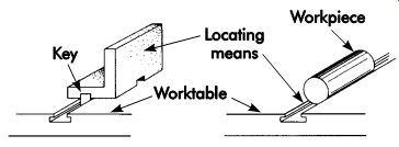
FIG. 11. Positioning a workpiece relative to locating means.
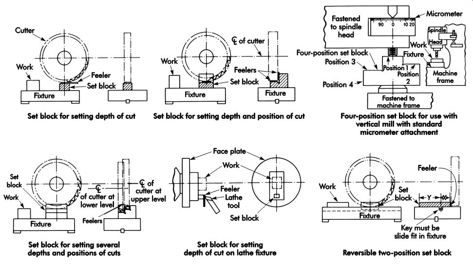
FIG. 12. Cutter settings with setup blocks and feeler setup gages.
The following step-by-step approach will prove valuable for the design of all fixtures.
1. View the workpiece as a whole. A study of the complete workpiece, including its intended function, will disclose the relationship be tween the various workpiece features. With this insight, the fixture designer can either establish or better understand a proposed sequence of operations. Such knowledge may enable the designer to combine operations and minimize fixturing.
2. Gather all necessary data. All information that may affect jig and fixture design should be readily available. The designer must know the physical characteristics of the workpiece, such as composition of the material, condition (hardness), and rough and finished weight. For example, if a workpiece is to be made directly from raw material (mill extrusions or sheet stock), the designer must know the shape, size, and tolerances of the mill stock. All production data, including total pieces, rate of production, tooling budget, and proposed production sequence must be available.
3. Consider standard workholders. Many operations can be performed by using available commercial workholders, such as machine vises, T-slots and bolts, jacks, and clamps.
The design of a special workholding jig or fixture must be economically justifiable.
If the planned operations are similar to present operations, the rework of present fixtures may be considered.
4. Determine the special workholders that will be required. Every proposed operation should be carefully examined to see whether it can be performed economically with commercial workholders (machine vises, etc.), or whether available fixtures can be used. The designer should also consider whether available fixtures with minor alterations can be used. After assigning as many operations as possible to commercial or available workholders, a small number of operations will remain, for which special workholders must be provided. The number of special workholders may be further reduced by combining operations within a single fixture.
5. Study fixtures for similar operations. Every operation for which a special workholder is required should be considered individually.
The designer should seek out-within his or her own plant, in other plants, in technical journals, etc.-similar operations for which fixtures are provided. By examining a number of existing fixtures, the designer can combine the best features of each.
6. Review the fixturing plan. The designer should consider, in turn, every operation of the production sequence and review fixturing decisions. There should be confirmation at every step that the proposed workholder will be structurally adequate to withstand cutting forces and deliver the precision required (location aspects). The preliminary design of the required special workholders should be completed.
7. Execute the fixturing plan. The designer should remain available during the execution of the fixturing plan. No plan can be regarded as final because of possible changes in work piece dimensions and the typical cut-and-try aspects of fixture planning. After the line has been used for production, further process improvement may suggest fixturing changes.
A well-designed fixture may be used on several different machines. FIG. 13 shows a work piece and its fixture as it might be processed in several different ways. The workpiece is a magnesium casting; the base and primary reference plane are established at the first milling operation. For the second milling operation, the workpiece is clamped to the fixture and repeatedly indexed to present four surfaces to the milling cutters. The rotating plate of the fixture has hardened bushings at 90° intervals, into which an index-pin plunger can nest.
Fixture design example
Fixtures, like jigs, should be designed using a systematic approach. Using a similar sketching technique as outlined in Section 5 (Jig Design), the following method may be used to design a simple plate fixture.
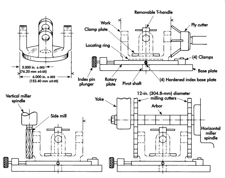
FIG. 13. Fixtured workpiece processed by several different methods.
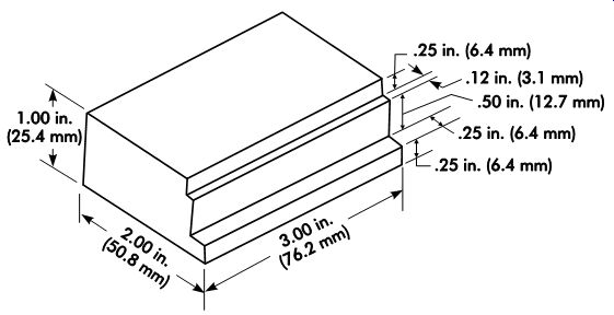
FIG. 14. Rough sketch of a stop block.
The part to be machined is the stop block in FIG. 14. The first step is to study the part and determine the basic requirements and relevant information about the part. In this case, the requirement is for a simple fixture to hold the part for gang milling a stepped shoulder. The part is 3 × 2 × 1 in. (76.2 × 50.8 × 25.4 mm) 6061-T6 aluminum barstock. The production plan calls for the part to be cut from 1 × 2 in. (25.4 × 50.8 mm) bar to a tolerance of 3 in. ±.005 in. (76.2 ±0.13 mm). The production run is specified as 750 parts per month. The fixture should be designed as a permanent tool, yet the cost must be kept to a minimum. Since gang milling is specified, a horizontal milling machine will be used to machine the parts.
Next, the part is sketched in three views (Figure 6-15). If possible, the part should be sketched full size. However, half or quarter scale can be used if the part is too large. Make the sketch as accurate and true to scale as possible. Sketching the part in a different color will help reduce confusion as the design develops and more lines are added to the initial design sketch.
Once the part is sketched, the base plate and part locators should be added to the sketch. As shown in FIG. 16, a simple six-point locating method is used since the part presents no special locational problems. In FIG. 16, the base plate acts as the primary Reference surface.
Since the primary Reference surface on the part is flat, no special locators, other than the base plate itself, are installed. The secondary Reference surface is located with two dowel pins positioned toward the rear of the plate. The final locator is positioned on the short side of the part, toward the end where the tool thrust will be directed.
This locational method will be sufficient to accurately locate the part and resist the cutting forces that can be expected. If, however, a different material, such as steel, were to be machined, a more substantial locator might be better suited.
In such a case, a block, screwed and doweled to the base plate, might be installed to resist the additional tool thrust.
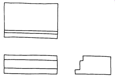
FIG. 15. The part is sketched in three views.
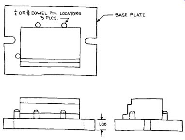
FIG. 16. A six-point locating method is used.
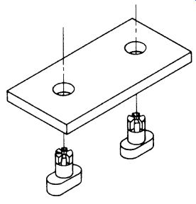
FIG. 17. Drill and ream fixture keys.
The base plate of 1-in. (25.4-mm) steel plate is selected for this fixture due to its low cost and durability. The top and bottom surfaces should be machined to provide accurate and parallel locating surfaces for both the part and the fix ture. The slots in either end provide a means to secure the fixture to the machine table. Drill and ream fixture keys are used to maintain the proper position of the fixture in the table's T-slot (FIG. 17). These were selected because of the relatively short time required for installation. Other standard fixture keys could be used (FIG. 18).
The set block is now sketched into the de sign. The block selected is made .0625 in. (1.588 mm) smaller than the actual part on both the referencing surfaces to accommodate the feeler gage. A feeler gage made from .0625 in. (1.588 mm) stock will be used to position the cutters in the initial setup of the fixture. The location of the set block is determined by the dimensions on the part print. As shown, the first step is dimensioned as 1.625 in. (41.28 mm) from the secondary Reference surface and .75 in. (19.1 mm) from the primary Reference surface. The set block then is positioned to suit these dimensions (FIG. 19).
The clamping device selected for this fixture is a toggle-action clamp. While any of several different clamps could be used, a toggle-action clamp offers the advantages of being fast-acting, capable of being moved completely clear of the part, and easily modified to suit the part's shape.
The cost of this clamp is also a consideration.
Since this is a commercial component, the cost is much less than making a similar clamp in house. The end of the toggle clamp is modified to suit the length of the part. This will spread the clamping force over a greater area and ensure that the part is properly held against the base plate (FIG. 20).
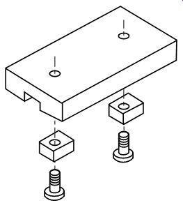
FIG. 18. Standard fixture keys.
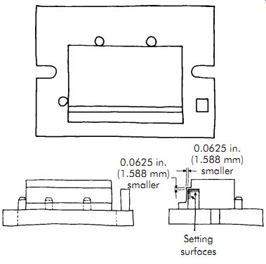
FIG. 19. Standard fixture key location.
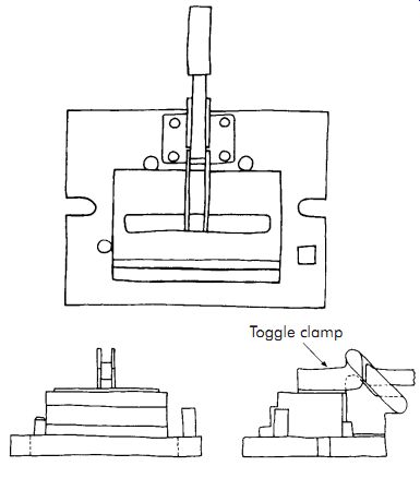
FIG. 20. A clamp is added to hold the part against the base plate.
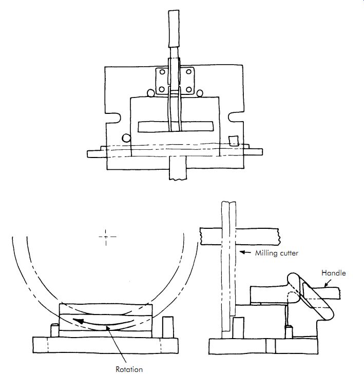
FIG. 21. Cutters sketched into the initial design.
The next step is selecting the cutters to per form the gang milling. The logical choice for this operation is interlocking, staggered-tooth, side milling cutters. The diameters of the cutters are normally determined by the size of the milling machine specified for the machining. However, for this example, the cutters specified have diameters of 5.00-6.00 in. (127.0-152.4 mm). Both cutter widths are .25 in. (6.4 mm). The cutters are now put into the initial design sketch (FIG. 21). The entire design now must be checked to make sure there is no interference between members or between the fixture and machine tool. Once this inspection is complete, the final tool drawings are prepared.
Other Refs.
The Society of Manufacturing Engineers (SME) has developed the Fundamentals of Tool Design video series, which comprises nine DVDs, of which one relates directly to this section's content: Fixture Design (20 minutes, order code: DV07PUB3 www.sme.org).
To correctly machine a part, it must be held in a fixturing setup that guarantees a definite location, or position, with respect to a part's datum points or surfaces. This must be repeatable, part after part.
Fixture Design explores the various issues influencing the development of fixtures, as well as the basic fixture types and classifications, including milling fixtures, lathe fixtures, grinding fixtures, and broaching fixtures. The use of component kits to quickly construct modular fixturing systems is also examined.
QUIZ
1. What are fixture keys? What purpose do they serve?
2. How are fixtures classified?
3. When designing a lathe fixture, what must be done to equalize unbalanced masses in the workpiece or fixture?
4. What type of fixture is the most economical for small parts?
5. What type of fixture could be used to ma chine a hexagonal shape on a shaft?
6. Why should fixtures have a low profile?
7. Why should standard components and cutters be used wherever possible?
8. Based on its construction, what type of fix ture is the most common?
9. Design a milling fixture for the part shown in Figure A. This is a temporary tool to machine slots in 250 pieces.
10. Design a fixture to perform the slotting operation on the part shown in Figure B. This is a high-volume part, but the cost of the fixture must be minimal.
11. Why are loose tool parts usually avoided in the operation of a jig or fixture?
12. List two advantages and two disadvantages of fabricating (welding) jig or fixture bodies/components.
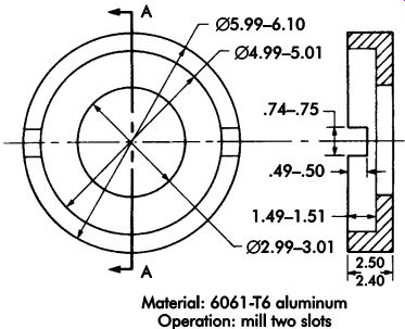
Figure A.
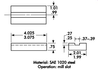
Figure B.