Jigs are workholders designed to hold, locate, and support a workpiece while guiding the cut ting tool throughout its cutting cycle. Jigs can be divided into two general classifications: drill jigs and boring jigs. Of these, drill jigs are by far the most common. Drill jigs are generally used for drilling, tapping, and reaming, but also may be used for countersinking, counter-boring, chamfering, and spot-facing. Boring jigs, on the other hand, are used mostly for boring holes to a precise, predetermined size. The basic design of both classes of jigs is essentially the same.
The only major difference is that boring jigs are normally fitted with a pilot bushing or bearing to support the outer end of the boring bar during the machining operation.
There are numerous considerations that must be addressed when designing any jig. Although several of these points, such as locating, supporting, and clamping, have already been covered, they are included in this section because they apply to jig design specifically. Since all jigs have a similar construction, the points covered for one type of jig normally apply to the other types as well. Jig design and selection begins with an analysis of the workpiece and the manufacturing operation to be performed.
General Considerations
One of the first considerations in the design of any workholder is the relative balance between the cost of the tool and the expected benefits of using it for production. All workholders should save more in production costs than they cost to design and construct. In many instances, tool de signers may have to complete detailed estimates to justify the cost of special tooling. This involves a close look at the part drawing, process specifications, and other related documents.
Typically, the complexity of the part, the lo cation and number of holes, required accuracy, and the number of parts to be made all must be considered to determine if the cost of a particular jig is warranted. Once the tool designer is satisfied that the cost of special tooling is justified, the remaining data required to produce a suitable workholder is compiled and analyzed.
Machine Considerations
The size, type, and capabilities of the machine tool specified for a particular operation have a direct bearing on how a particular jig should be made. For example, a jig intended for small holes drilled on a sensitive drill press will not normally have the same features as a jig designed for use with a larger radial drill press. While both may share many details, the machines they are used with, as well as the specific tooling required, will generally dictate the overall construction of the workholder.
Often, the tool designer is not the individual who specifies a particular machine tool for a machining operation. In most instances, the process engineer is responsible for specifying the machine tool, which is done before the tool design is started. However, the tool designer should check the specified machines to ensure they are the best possible choices. Following are a few machine considerations to keep in mind when designing jigs.
• The machine should be large and rigid enough to perform the desired operations.
• Production capabilities and accuracy of the machine tool should be suitable for the operation.
• The machine tool must safely accommodate the workholding device.
• The machine selected should be located close to subsequent machining operations.
Here, the plant layout is important to minimize the distance between machining stations and prevent backtracking and lost time.
• Specified cutting tools must be compatible with the machine tool. A lathe with a #2 Morse taper in the tailstock spindle can not hold #3 Morse taper tools without an adapter.
• Whenever possible, standard-size cutting tools should be specified. Special drills, reamers, and other cutting tools are expensive.
The tool designer should have all of the relevant specifications for each type of machine tool used for part production. This information should include table sizes, T-slot sizes, machine travel in all axes, and similar data. Such information is typically supplied by the customer or available in the maintenance manuals furnished with each machine. This saves the designer the time required to take measurements directly on the machine tool. A similar specification sheet should be maintained for each standard cutter normally used in the shop. This information is available from the cutter manufacturer, and should include the length of the tool, length of the effective cutting area, shank size, and similar data.
Process Considerations
Process considerations include the type of jig, number of jigs needed, and specific step-by step processing of the workpiece. While the proposed processing of a part is normally a function of process engineering, the tool de signer should always double-check to ensure the proposed tooling will be compatible.
First-operation jigs are normally used for work pieces without prior machining or any reliable Reference surface. Here, the first holes or surfaces are put into the part and act as a Reference point for any subsequent machining. First-operation jigs generally use adjustable supports, adjustable locators, or sight locators to set the initial position of the part to machine the first operations.
More than one jig may be used when several different operations must be performed on the same part. The most important point to consider is the repeatability of the location in each of the jigs.
In these cases, the same location point should be used for all machining operations on the part.
Other considerations that should be analyzed before a final design is determined include the actual processing methods, chip control, and disposal. Several parts may, in some cases, be stacked or aligned so more than one can be drilled at a time. Likewise, when large drills must be used to produce the required size hole, smaller step drills can be used to lessen the thrust and torque required to drill the holes. Here, a smaller or lighter-duty drill press must be used if a drill press of the proper size is unavailable. Chip control and disposal are considerations that must be remembered when designing a workholder.
Chips and coolant are normally removed with a brush or airflow, so adequate slots or open areas should be provided to permit easier removal (see FIG. 1).
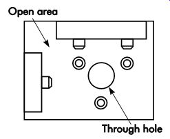
FIG. 1. Areas to permit easy coolant and chip expulsion.
Drill Jigs
The workpiece, production rates, and machine tool selected normally determine the size, shape, and construction details of any jig. However, all jigs must conform to certain design principles for the efficient and productive manufacture of quality workpieces. There must be a method to:
• correctly locate the workpiece with respect to the tool;
• securely clamp and rigidly support the work piece during the operation;
• guide the tool, and
• position and/or fasten the jig on a machine.
These methods will ensure interchangeability and accuracy of parts, plus provide the following advantages:
• minimize tool breakage;
• minimize the possibility of human error;
• permit the use of less skilled labor;
• reduce manufacturing time; and
• eliminate retooling for repeat orders.
Jigs are often divided into two broad categories-open and closed. Open jigs are used when machining a single surface of a workpiece, whereas closed jigs are used when machining multiple surfaces. Examples of open and closed jigs are shown in FIG. 2. Jig types are often identified by the method used in their construction (for example, template, plate, leaf, channel, etc.). The main types are discussed in the following sections.
Template drill Jigs
Template drill jigs are not actually true jigs because they do not incorporate a clamping device. However, they can be used on a wide variety of parts and are among the simplest and least ex pensive drill jigs to build. However, they are typically less accurate. Template drill jigs are simply plates containing holes or bushings to guide a drill. They are placed directly on a feature of the part to permit drilling holes at a desired location.
When this is impractical, they are located on the part by measurement or sight lines scribed on the template.
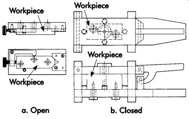
FIG. 2. Open and closed types of drill jigs.
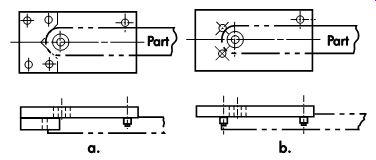
FIG. 3. Flat-plate template drill jigs.
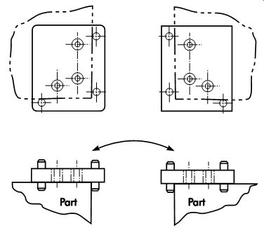
FIG. 4. Flat-plate template drill jig-left- and right hand.
Two flat-plate template drill jigs are shown in FIG. 3. Both are designed to drill a hole through the center of the rounded end of a lever.
The jig shown in a consists mainly of a drill guide plate and locating V-block. The jig in b does the same job, but has been further simplified by using dowel pins to accomplish the same centralizing action as the V-block.
Another flat-plate template drill jig is shown in FIG. 4. This jig was designed to drill a three-hole pattern into either a left- or right-hand version of a workpiece. Pins protrude from both sides of the drill plate, thereby permitting it to be flip-flopped to suit the workpiece being drilled.
A common practice with template drill jigs is to place a pin into the first hole drilled to prevent excessive movement of the jig while drilling the remaining holes.
Three circular-type template drill jigs are shown in FIG. 5. All are designed to locate from the maximum material condition (MMC) of the part diameter. Jig a is designed to locate from the outside diameter (OD) of a shaft, jig b from the inside diameter (ID) of a part, and jig c from a boss diameter. In all cases, a pin of the proper size is placed into the first hole drilled to properly position the jig to drill the second hole.
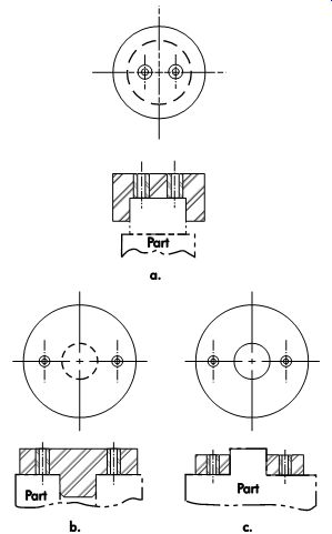
FIG. 5. Circular-plate template drill jigs.
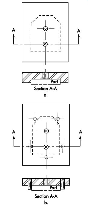
FIG. 6. Nesting template drill jigs.
FIG. 6 illustrates two nesting-type template drill jigs. Jig a is designed to locate a small sheet metal workpiece in a cavity to permit drilling two holes, which are located from the periphery of the workpiece. Jig b is designed to perform the same operation by using five dowel pins press-fitted into the jig in lieu of the cavity to locate the workpiece, reducing the cost to build the jig. A template drill jig is often used to drill holes in one portion of a large workpiece since a conventional jig large enough to hold the entire part would be impractical and costly. Template jigs usually cost much less than conventional jigs, often making the use of two or three template drill jigs more economical than using one large conventional jig.
Here are some of the main disadvantages of template jigs.
• They are not as foolproof as most other types, which may result in inaccurate machining by a careless operator.
• Orientation of the hole pattern to workpiece datums may not be as accurate as with other types of jigs. However, the accuracy of the hole pattern within the template jig itself is comparable to that of any conventional jig.
• They are not practical when locating datums are dimensioned regardless of feature size (RFS).
Plate Jigs
Plate jigs are basically template jigs equipped with a workpiece clamping system. Initial construction costs are greater for plate jigs than for template jigs, but plate jigs are generally more accurate and last longer.
A plate jig incorporates a plate, usually the main structural member, which carries the drill or liner bushings. Slip bushings of various sizes can be used with liner bushings, allowing a series of drilling and related operations without the need to relocate or re-clamp the workpiece. The plate jig's open construction makes it easy to load and unload a workpiece and get rid of chips.
Three different types of plate jigs are shown in FIG. 7. The open-plate jig shown in a is basically a template jig equipped with a means to clamp the workpiece, with work supported by the drill press table. The table-plate jig in b consists of a drill plate, locating stud, and clamping screw with standard screws used as jig feet. This type of jig is usually handheld on the drill press table, rather than clamped to the table, so it may be easily inverted for loading and unloading. Consequently, table-plate jigs are generally used for small parts. Note in particular that tool thrust in this type of jig is directed toward the clamps rather than the rigid portions of the jig. Therefore, it is imperative that the clamping method be strong enough to resist the thrust of the drill.
For obvious reasons, the jig shown in c is called a sandwich-plate jig. With this type of jig, the workpiece is positioned between two plates: a drill plate containing the drill jig bushings, locators, and clamps, and a backup plate to provide support only. The backup plate has clearance holes for the drill and is aligned with the drill plate by two pins. The backup plate is ideal for supporting thin parts that would otherwise buckle from the thrust of the drill.
The angle-plate jigs shown in FIG. 8 are primarily used to drill workpieces at an angle to the part locators. The right-angle-plate jig in a is designed to drill holes perpendicular to the locating surface, while the modified-angle-plate jig, b, is designed to drill holes at angles other than 90° to the locating surface.
Plate-type jigs are usually moved around the table by hand. Therefore, special safety pre cautions should be provided to prevent the jig from whirling around the spindle whenever a cutting tool jams. The best way to prevent this is to build the jig with an extension handle long enough for the machine operator to overcome the torque of the jammed tool. When a plate jig is used with a radial drill, a provision can be made to clamp the drill jig or workpiece to the machine table.
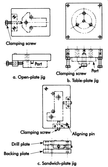
FIG. 7. Plate jigs.
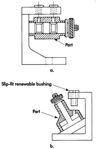
FIG. 8. Angle-plate jigs.
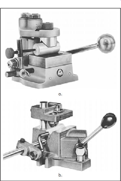
FIG. 9. (a) Universal jig ready for production, (b) adjustable cross-hole
drill jig
Universal Jigs
Universal jigs (sometimes called pump jigs) utilize a handle connected to a cam or rack and pinion to move either a bushing plate or a nest plate, often vertically, to clamp the workpiece.
Parts held in universal jigs have surfaces adapt able to fitting against the surfaces of the bushing plate and nest.
Universal jigs are readily available in a wide variety of styles and sizes. They are well designed, ruggedly built, and can be easily prepared to drill a specific part. Usually, all that is required is to add part locators and drill jig bushings.
Some typical applications are shown in FIG. 9. Jig a was set up to drill a hole through the center of a small rod. It features a self-locating V-bushing liner, an adjustable end stop, and a riser block. This same operation could be accomplished with another type of universal jig called a cross-hole jig, b, also shown in FIG. 9. In this jig, the drill is guided by a standard slip-fixed renewable bushing, which is fitted into the jig clamping plate and precisely centered above a hardened and ground V-block. Either of these jigs could be easily adapted to drill a wide variety of parts, each having a different diameter or hole size, merely by changing the renewable slip-fixed jig bushing and adjusting the end stop.
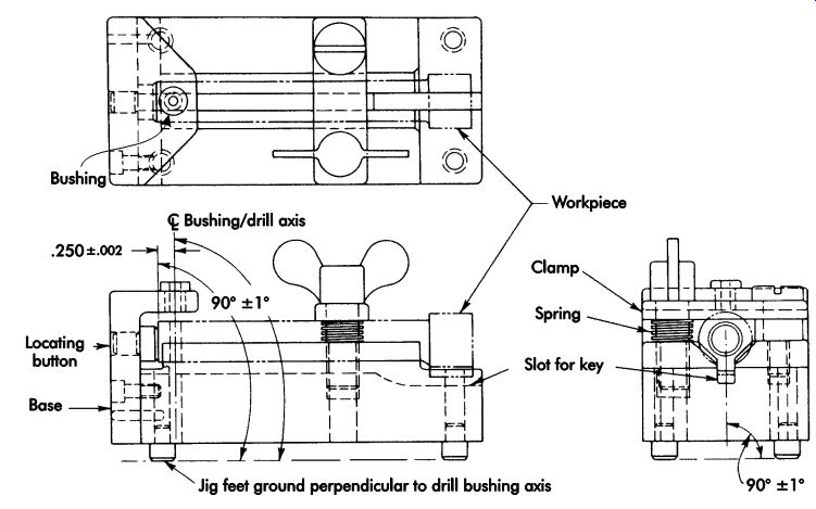
FIG. 10. Plate jig for cross-hole drilling.
Compare the jigs in FIG. 9 with the plate jig shown in FIG. 10, which was specifically designed and built to perform a similar operation.
Needless to say, the universal-type jig could be put on the job in a fraction of the time and at a lower cost. By utilizing the wide variety of standard drill bushings, liners, and tooling components, universal jigs can be adapted to drill a wide variety of parts. Also, they are reusable for other jobs, although this may require replacement of the drill plate, which is interchangeable and available separately from the manufacturer. Because of this versatility, universal jigs are ideal for limited production manufacturing. One manufacturer states that tooling costs can be reduced by one third. With few exceptions, universal jigs can be designed and adapted to do a job in a fraction of the time required to design and build a conventional jig to perform the same function.
Leaf Jigs
A leaf jig is generally small and incorporates a hinged leaf that carries the bushings, and through which clamping pressure is applied. Although the leaf jig can be used for large and cumbersome workpieces, most designs are limited in size and weight for easy handling. A leaf jig can be box like in shape, with four or more sides for drilling holes perpendicular to each side. Leaf jigs with additional feet are often called tumble jigs. They permit operations from more than one side.
Off-the-shelf, tumble-type leaf jigs are avail able in a variety of sizes from many manufacturers. Construction consists of a drill plate (leaf)
attached to the jig body with a precise-fitting hinge at one end and a positive positioning clamp at the other end. As with universal jigs, all that is required to prepare it for use is to provide a means to locate the part and add drill bushings.
Lids swing up to provide easy loading from three sides. Occasionally, a side plate is attached to the lid or base to permit cross-drilling.
The leaf jig shown in FIG. 11 was specifically designed and built to drill two holes in a small connecting rod. The hinged drill plate contains the drill bushings and is precisely located at both ends by the slots in the body of the jig.
The workpiece is located and clamped between two V-blocks, one fixed and the other movable.
The V-blocks are tapered to force the workpiece down against the base of the jig body.
Channel and Tumble-box Jigs
Channel and tumble-box jigs permit drilling into more than one surface of a workpiece with out relocating the workpiece in the jig. This results in greater accuracy with less handling than using several separate jigs. These jigs can be quite complicated and more expensive to build than simpler types, but they can still be cost effective if properly designed. An example of a channel jig is shown in FIG. 12.
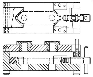
FIG. 11. Leaf jigs for drilling two holes in a small connecting rod.
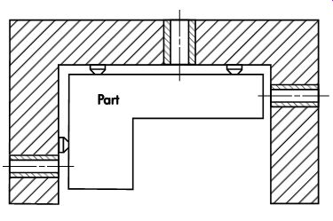
FIG. 12. Cross-section of a typical channel jig (clamping details not shown).
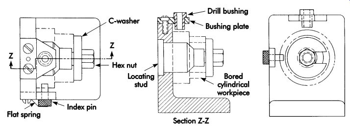
FIG. 13. Simple indexing jig with standard angle-iron base.
The channel jig in FIG. 12 was designed to drill holes into three surfaces. A U-shaped channel was used as the main body, along with press-fit drill bushings, locators, and clamping details.
The U-shaped channels used to construct this jig can be cast, built-up, or of welded construction.
However, to keep building costs to a minimum, the designer should consider using the standard U-shaped sections discussed previously.
Tumble-box jigs permit drilling and similar operations from all six sides. They are commercially available in a variety of sizes, which can be prepared to machine a particular part by adding drill bushings and a means to locate and clamp the part. Because of this off-the-shelf availability, designers often choose a tumble-box jig over a channel jig when machining only two or three sides of a workpiece.
Indexing Jigs
Indexing jigs are used to drill holes in a pat tern, usually radial. Location for the holes is generally taken from the first hole drilled, a datum hole in the part, or registry with an indexing device incorporated in the jig.
The simple jig shown in FIG. 13 features a base made from a standard angle-iron section, into which a locating stud has been placed to position a bored cylindrical workpiece, which is clamped on the stud with a C-washer and a hex nut. A drill bushing is press-fit into the bushing plate. In use, the hex nut is loosened after the first hole is drilled, the workpiece is revolved, the index pin, which is held in place with a flat spring, is pushed into the hole, and the second of four holes 90° apart is drilled after the nut is tightened. Indexing is repeated until all four holes have been drilled.
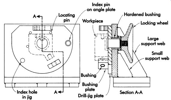
FIG. 14. Indexing jig of welded construction.
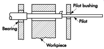
FIG. 15. Boring jig.
Another indexing jig, shown in FIG. 14, utilizes an angle plate of welded construction.
A spindle pressed into the jig's pivot point is threaded on one end for the locking wheel.
Clamping for the workpiece is not shown. The workpiece, bushing plate, and bushings are rotated for drilling holes at various angles, which are determined by the location of the index holes in the jig and angle plate.
Boring Jigs
Boring jigs are quite often constructed similarly to box jigs. The principal difference between boring jigs and box drill jigs is the bearing point on the side opposite the surface to be machined.
As shown in FIG. 15, the workpiece is located and clamped inside the box. The boring bar is then passed through the part and the pilot bearing is aligned in the bore on the opposite side of the jig. The part is then bored by feeding the rotating boring bar into the part. In some designs, both the outer end of the boring bar and the driven end of the bar are supported during the boring cycle. This design is normally used where extreme accuracy is of prime importance.
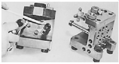
FIG. 16. Drill jig made from a standard T-section.
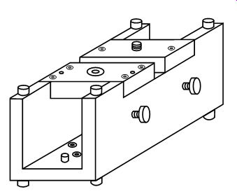
FIG. 17. Drill jig made from a standard U-section.
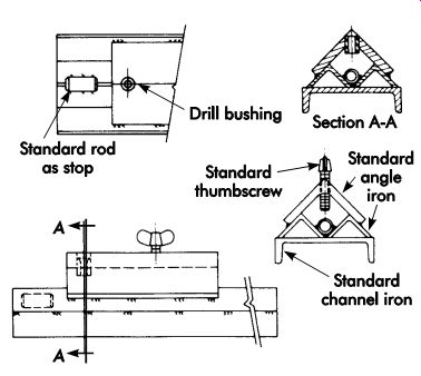
FIG. 18. Drill jig made from a standard structural form material (channel
and angle iron).
Miscellaneous Drill Jigs
Drill jigs can be made from many standard commercial items, such as: pre-machined section forms and bases; angle irons, parallels, and V-blocks; section components; and standard structural forms. Following are some examples of drill jigs constructed of these materials.
• Pre-machined sections were used to con struct the drill jig shown in FIG. 16. The base was made from a standard commercial T-section, to which a bushing plate, made from a flat section, was attached with screws and dowels. The addition of standard jig feet, drill bushings, and clamps completed the assembly.
• The drill jig shown in FIG. 17 was built from a U-shaped, pre-machined cast-iron section and a flat section. It was built in 9.5 hours with a savings of 30% in build time.
• The drill jig shown in FIG. 18 was built from standard structural form materials. It consists of two pieces of angle iron welded to a channel iron to form a V-section. A larger angle iron was welded over the V-section to serve as a bushing plate and clamping mount. The addition of a standard thumb screw, drill bushing, and section of rod completed the assembly.
Wooden drill Jigs
Often overlooked, wooden drill jigs are limited by their inherent inaccuracies. An example of a wooden drill jig used for drilling is shown in FIG. 19. The jig consists of a plywood base, two wooden side spacer rails, a plywood bushing plate joined together with wood screws, and four bolts that also serve as jig feet. To reduce wear and provide additional support, a sheet-metal plate is bonded to the top of the base. The part is located against a pressed-in roll pin and two more bolts through the side rail. The hand-knob clamp, thumbscrew, threaded socket, and serrated-type bushings are all standard tooling components.
Polymer drill Jigs
Some issues that require special consideration when using polymer materials for drill jigs include the following.
• Conventional drill bushings should not be used. Castable drill bushings are designed for this purpose and should be used.
• Drill bushings must be positioned in the exact location before pouring liquid epoxy, thermoplastic compound, or low-melt alloy.
• When designing epoxy tooling, the tool designer should understand the various construction methods available, along with the advantages and disadvantages of each method. The designer also should be familiar with the many grades of epoxies, or seek help from the epoxy suppliers, especially when designing complex tooling.
General construction of a cast epoxy drill jig is shown in FIG. 20. A drill jig constructed by the laminating method is shown in FIG. 21.
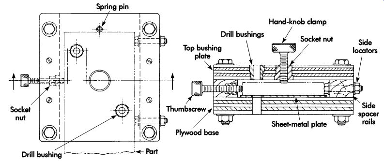
FIG. 19. Wooden drill jig incorporating standard tooling hardware.
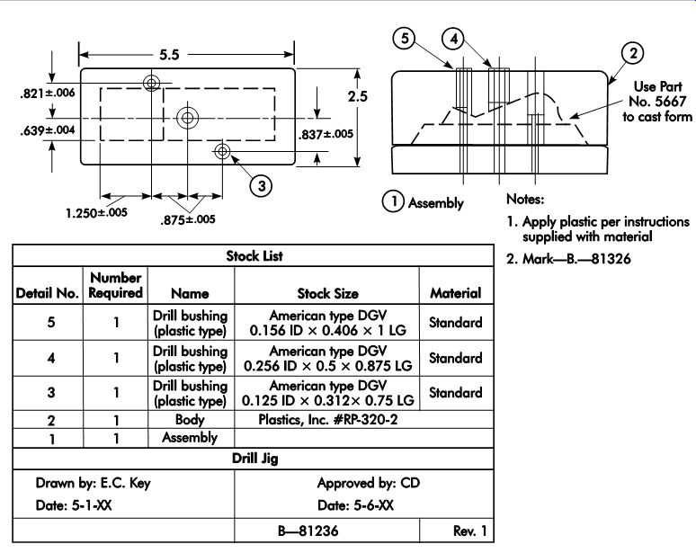
FIG. 20. Drawing of an epoxy drill jig.
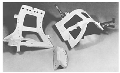
FIG. 21. Plastic drill jigs and scribe templates.
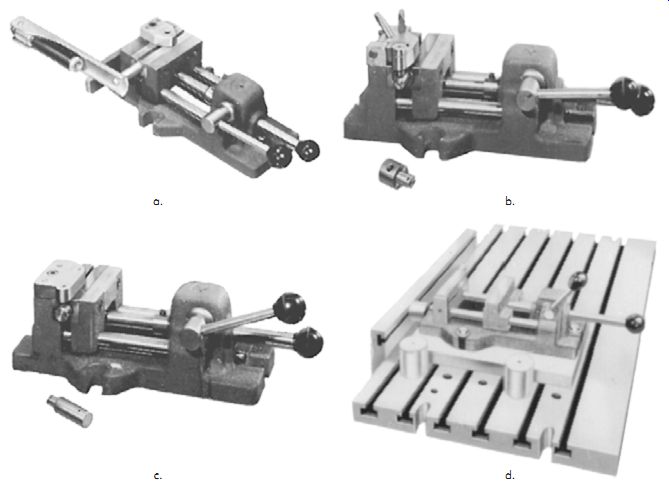
FIG. 22. Modified vises.
Modified Vises
The drill jigs shown in FIG. 22, along with their respective workpieces, were made by adding details to a commercially available vise.
The first jig, a, was designed to drill a locating hole in a sprocket shaft. The second jig, b, was designed to both drill one .277-in. (7.04-mm) diameter hole and drill, countersink, and tap a .3125-24 in. hole in a pivot block. The third jig, c, was designed to drill (1) No. 38 and (1) .094- in. (2.39-mm) diameter hole in a pivot pin. For positioning on the machine table, the vises are bolted to precision-ground sub-bases and located against a rail and stop pins as shown in d.
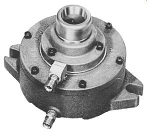
FIG. 23. Air collet fixture.
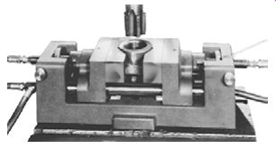
FIG. 24. Self-centering vise with false jaws.
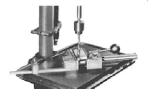
FIG. 25. Safety drill vise.
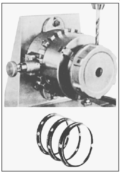
FIG. 26. Quick divider.
Collet Fixtures
As shown in FIG. 23, collet blocks and collet fixtures mounted vertically can be used to hold workpieces for drilling, tapping, and related operations. The collet fixture shown has been mounted on a sub-base to permit long workpieces to pass through the fixture.
Self-centering Vises
The self-centering vise shown in FIG. 24 was fitted with false jaws to center and clamp a cast-iron elbow for drilling and tapping. Form fitting cast jaws perform a similar function.
Drilling accessories
The safety quick-acting drill vise shown in FIG. 25 features built-in recessed parallel jaw inserts to hold work square. A vertical V-groove in the jaw is provided to grip round workpieces.
Also shown is the method of mounting the vise to a table to prevent it from spinning or breaking loose from the table. The quick-dividing device shown mounted to an angle knee in FIG. 26 can speed up the drilling of equally spaced pat terns of 2, 3, 4, 6, 8, 12, or 24 holes on a work piece's outside diameter. Or, when used without the knee, it can facilitate drilling equally spaced hole patterns on any bolt-circle diameter on the face of a workpiece.
The universal drill jig shown in FIG. 27 can be readily adapted for drilling a wide variety of workpieces. It features a solid jaw with an adjustable end stop and several movable bushing carriers, which can be oriented for different workpieces.
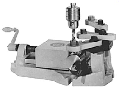
FIG. 27. Universal drill jig.
A mounting table for various drilling applications can be used for light drilling as well as electrical discharge machining (EDM), milling, boring, and jig grinding. The workpiece is located and held on the square ledges of the rails and a movable support block permits the fixture to be used for a wide range of workpiece sizes. The application shown in FIG. 27 is a setup for a numerically controlled (NC) drill press.
A drill press clamp can be useful for clamping a workpiece directly on the drill press table. It also can be used to guide a drill by replacing the clamp screw with a suitable drill bushing.
Drill Jig Bushings and Liners
Drill jig bushings guide the tools that do the cutting. They are available in hardened steel or carbide. Bushings made of other materials, such as bronze and stainless steel, are available from bushing manufacturers by special order. Most bushings and liners can be supplied with the outside diameter (OD) ground to industry standards, or left un-ground (type U) for custom grinding.
Selection
Drill jig bushings and liners may be specified either by the individual manufacturer's identification system or by the universally accepted American Society of Mechanical Engineers (ASME) designation system (ASME B94.33), which, regardless of the manufacturer, will ensure delivery of the proper bushing. Specifying the type of cutting tool and its diameter will ensure correct tool clearance. Standard, off-the shelf bushings are the least expensive.
Extended range bushings and liners are avail able in sizes larger than ANSI standard (Types P, H, SF, L and HL). Their outside diameters are typically un-ground, which allows for custom grinding. The reduced wall thickness and head diameters of extra-thin-wall bushings (available in Types P, H, and SF) save space where extremely close hole patterns must be accurately drilled.
Although extra-thin-wall bushings are as durable as regular wall thickness bushings, they will not necessarily be round in their free state.
Embedment bushings are designed specifically for use in soft materials such as aluminum or magnesium and can be used in jigs or fixtures made of laminated fiberglass or castable potting compounds. Three types are available: diamond groove, ser groove, and spline lock.
Tungsten-carbide bushings are extremely hard (RC 78-80). They can last up to 50 times longer than conventional steel bushings and are avail able in Types CP, CH, and CSF. Titanium-nitride (TiN) -coated bushings can last up to 40 times longer than conventional steel bushings. They yield excellent results where long wear is needed and where carbide may be too brittle. TiN bushings are more cost effective than carbide bushings when larger quantities (can be as low as three pieces, depending on size) are involved.
Before selecting a compatible bushing, it is helpful first to define the specific needs and parameters of the application:
• How will the bushing be used (to drill, tap, or ream)?
• What type is required for the process (head less, headed, or slip-fixed renewable)?
• What is the size of the production run? Tungsten-carbide or titanium-nitride-coated bushings, even at a slightly higher cost than standard steel, will last longer for long production runs.
• What are the hole size, outside diameter (OD) size, and length?
• Are there any special requirements (threaded OD, angles, flats on head, special dimensions, etc.)?
• Will the application require a standard or special size? Standard sizes are less expensive.
Is a special bushing really necessary or will a standard one fill the requirement? Bushing/liner installation
To ensure accuracy in the workpiece, drill bushings must be properly located and installed.
The following factors should be considered when installing cast iron or unhardened steel jig plates: alignment, diametral interference fits, chip clearance, and how close the bushing is to the workpiece. Because of the number of variables, no definite rules can substitute for the skill and judgment of the experienced toolmaker.
Mounting holes should be round and properly sized to prevent bushing closure and jig-plate distortion. For this reason, it is recommended that the mounting holes be jig-bored, reamed, or ground to size to assure roundness. Ordinary twist drills seldom produce an accurately sized or truly round hole.
For production accuracy, extra care is required when preparing mounting holes and installing bushings/liners. It is recommended that the inside diameter of the mounting hole and the outside diameter of the bushing/liner are lubricated before pressing into place. Lubrication prevents scoring of the hole wall. White lead is typically used as the lubricant. Further, an arbor press should be used to press the bushing/liner into place. If an arbor press is not available, the bushing/liner is drawn into place by tightening two steel plates connected by a nut and bolt. A bushing/liner should never be hammered into place.
Use of a lock-liner bushing and lock nut is the conventional method of mounting the drilling unit to a jig or fixture. To install it, a hole is bored into the jig or fixture to suit the lock-liner bushing. It is then assembled to the jig or fixture and held in place with a lock nut.
Direct jig mounting is an alternate method, used when holes are so closely spaced that lock-liner bushings cannot be used. In this case, lock screws are mounted directly on the jig and a hardened, headless liner is pressed into the jig to accept the drill bushing tip shank.
Lock-strip mounting is another mounting method used for holes that are closely spaced.
It features a lock strip along each side of a row of holes in the jig. A hardened, headless liner to accept the shank of the drill bushing tip is also pressed into the jig with this method.
Drill bushings for special applications should be installed in accordance with the individual manufacturer's recommendations.
Interference Fits
Interference holds press-fit bushings (FIG. 28) in place on the jig plate. However, too much interference may cause a number of problems:
• jig plate distortion,
• bell-mouthing (bushing/liner walls bow in ward),
• tool seizure, and/or
• trouble with the slip-fixed renewable bushing fitting into the liner.
Too little interference may allow slippage, thus causing inaccurately drilled holes. In most cases, interference of .0005-.0008 in. (0.013-0.020 mm) is sufficient to properly install press-fit bushings and liners.
Headless-press-fit and liner bushings generally are installed with a diametral interference of .0005-.0008 in. (0.013-0.020 mm), while headed-press-fit bushings are generally installed with a diametral interference of .0003-.0005 in. (0.008-0.013 mm). Interference greater than this may reduce the ID of the bushing to the point where the tool may seize or, in the case of liners, prevent insertion of a renewable bushing. On the other hand, too little interference will result in a loosely installed bushing that may spin or be forced out of place.
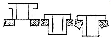
FIG. 28. Bushing fit.
Chip Clearance
One school of thought suggests that a space exist between the workpiece and the drill bushing. The other suggests direct contact. The decision as to which to choose takes into consideration the abrasiveness of the material being drilled, the drill size, and the type of bushing/liner being applied. Sufficient chip clearance, as illustrated in FIG. 29, should be provided between the bushing and workpiece to enable chip removal, except in cases where extreme accuracy is required. In this case, the bushing should be in direct contact with the workpiece.
To properly support and guide the cutting tool, the length of the drill bushing under nor mal circumstances should range between 1.5-2.5 times the bushing's ID. And, the jig plate sup porting the bushing should be thick enough to sustain the bushing. Usually, between 1-2 times the cutting tool thickness will be sufficient.
A clearance of 1-1.5 times the bushing ID should be used when machining materials such as cold-rolled steel, which produces long stringy chips. A clearance of 0.5 times the bushing's ID is recommended when machining materials such as cast iron, which produces small chips. Excessive chip clearance should be avoided because most cutting tools are slightly larger at the cutting end due to back taper, and excessive clearance will reduce the guiding effect of the bushing, resulting in less accurate drilling.
Clearance between the bushing and the work piece is also important when drilling wiry metals, such as copper, which tends to produce secondary, or minor, burrs around the top of the drilled hole as shown in FIG. 30. This, in turn, causes the jig to lift from the workpiece or makes it difficult to remove the workpiece from side-loaded jigs. A burr clearance of 0.5 times the bushing's ID is recommended. The jig itself must also provide clearance for the primary, or major, burrs that form as the tool exits the workpiece.
Varying the length of the slip-fixed renewable bushings is used to achieve proper spacing for the application. However, a rule of thumb is, the greater the space between the bushing and work piece, the greater the chance for error. When making an adjustment, it is advisable to do so under test conditions first and, in production, continue to check for accuracy throughout the run. Chip control should be closely monitored after the jig is put into production. As a general rule, if the chips have a tendency to lift the bushing, more clearance is needed. If the cutting tool wanders or bends, less clearance is needed.
When performing multiple operations, such as drilling and reaming, slip-renewable bushings of different lengths should be used to provide optimum chip clearance for each operation as shown in FIG. 31.
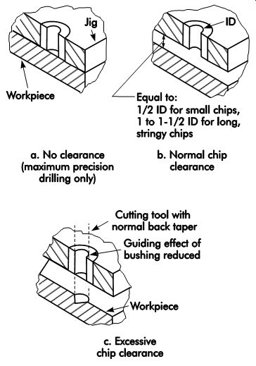
FIG. 29. Recommended clearance between workpiece and bushing.
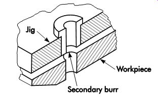
FIG. 30. Burr clearance.
Chips produced from drilling will be ejected either through a space or through the bushing (FIG. 32). If the drill clogs or heats up, it is advised to increase the space between the end of the bushing and the workpiece. Normal spaces vary from one-half the drill diameter for small chips (as from cast iron) to one and one-half times the drill diameter for long stringy chips (as from cold-rolled steel).
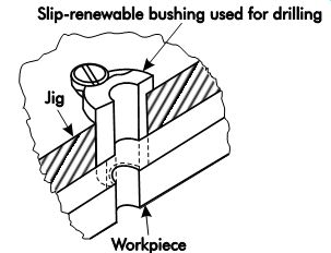
FIG. 31. Slip-renewable bushings provide chip clearance for multiple operations.
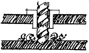
FIG. 32. Chip clearance.
Accuracy and Life
Following are some tips to ensure more accurate production and longer bushing life.
• Align bushings properly. Carefully align the drill with the bushing axis to avoid excessive wear. The radius on the bushing will help center the drill point.
• Keep tools sharp. Dull drill bits defeat the preciseness of bushings. Sharpen by first grinding each drill with the point in the exact center. This prevents the drill from "walking" when it first enters the workpiece.
• Use proper coolants. Check the coolant label to be sure it is the right one for the particular machining process at hand.
• Use slip-fixed renewable bushings for multiple operations. Differing lengths of slip fixed renewable bushings provide for both accuracy and chip removal during multiple operations. For example, a short bushing during drilling will provide the proper clearance for chips to escape; a longer bushing during reaming will provide maximum guidance.
• Adapt bushings to irregular work surfaces.
The exit end of the bushing should conform to the contours of the workpiece as shown in FIG. 33. This will prevent the tool from pushing off center. For maximum guidance, the space for chip clearance should be held to a minimum. A drill point that does not enter exactly perpendicular to the work surface will skip or wander. In such a case, side load exerted by the drill is concentrated near the exit end of the bushing and can cause the bushing to wear prematurely.
Slip-fixed renewable bushings can simplify the replacement of worn bushings, and also aid in alignment with the contoured work surface. For short production runs using press-fit bushings, the bushing's end is formed to the workpiece's contour.
• Sometimes, hole center distances are so close that there is not enough room for the bushings. In these cases, extra thin wall bushings or standard headed or headless bushings that have flats ground on them might work. Some times a single, hardened steel insert with two or more holes must be used.
• Use tungsten-carbide or titanium-nitride (TiN)-coated bushings for long production runs. Tungsten carbide bushings last up to 50 times longer than hardened steel. Titanium-nitride-coated bushings can last up to 40 times longer than conventional bushings.
Both types of bushings can save valuable replacement downtime. The additional cost of these bushings is small in consideration of their extra long life.
Headless-press-fit Bushings
Headless-press-fit bushings of Types P (Fig. 34) and PU are the most popular and least expensive. They are used in single-size cut ting-tool applications where light axial loads are expected and in single-stage drilling operations.
Since they are permanently pressed into the jig plate, they are generally used where replacement is not anticipated during the expected life of the tool. They mount flush with the top of the jig plate, so they are ideal where the top of the bushing must be flush or where hole spacing is too close to use headed bushings. They are avail able with finish-ground outside diameters or un-ground for custom grinding.
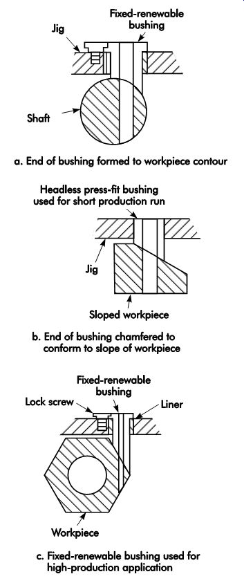
FIG. 33. Drilling irregular work surfaces.
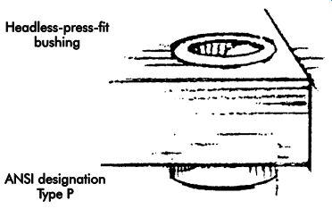
FIG. 34. Headless press-fit bushing.
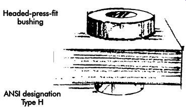
FIG. 35. Headed press-fit bushing.
Headed-press-fit Bushings
Headed-press-fit bushings of Types H (FIG. 35) and HU are used for permanent installations requiring greater bearing area or where heavy axial loads that could force the bushing through the jig hole are anticipated. They are the same as headless-press-fit bushings, but with a head (or shoulder) on the drill entry end, which prevents an axial load from forcing the bushing through the jig hole. Although designed for permanent installations, press-fit bushings are easily replaced, but at the expense of losing some mounting hole accuracy with each replacement.
Since the bearing area extends beyond the jig plate, the thickness of the jig plate often can be reduced, thereby lightening the overall weight of the jig. Cases where the head must be flush with the jig plate require counterboring of the mounting hole in the jig plate. Headed-press-fit bushings are available with finish-ground outside diameters or unground for custom grinding.
Slip Renewable and Slip-Fixed Renewable Bushings/liners
Slip renewable bushings (Type S) and slip fixed renewable bushings (Type SF) are used with a headless liner (Type L) or a head liner (Type HL) where multiple operations, such as drilling and reaming or drilling and tapping, are to be performed on the same hole. They are also used where long production runs require occasional changing of the bushing to maintain jig integrity.
When Type SF is used with a liner, it is permanently pressed into the drill jig. Slip renewable and slip-fixed renewable bushings (FIG. 36) can be used with lock screws (Types LS and TW), round clamps (Type CL), round end clamps (Type RE), or flat clamps (Type FC). Both diameters of the bushings and the inside diameter (ID) of the liner are finish-ground to industry standards, while liners are available with the outside diameter (OD) finish ground or unground. The OD of Type SF has a slip-fit tolerance for easy insertion or removal from the liner.
When used for multiple operations, the first operation bushing is installed and the hole drilled. The bushing is then replaced with the second operation bushing and the second operation is performed. This process is repeated until the hole is completely machined. The first operation bushing is then reinstalled and the procedure repeated on the next workpiece.
When slip-fixed renewable bushings are used on jigs to perform single operations on long production runs, which may be longer than the life of the bushing, they are usually secured in the fixed mode by a lock screw or clamp that fits a milled recess in the head. To perform more than one operation on the same hole, such as drilling followed by reaming, Type SF is secured in the slip mode for easy changing without disturbing the workpiece. The flexibility of having the fixed mode and slip position options lowers inventory costs. And, the knurled head of Type SF allows easy handling; just turn and lift.
Type UL (UN-A-LOK® ) liners are used with ANSI slip-renewable bushings. These special liners eliminate the need for a bushing locking device. In use, the bushing is locked tight in the liner by the torque of the drill bit. UL liners must be installed with an arbor press.
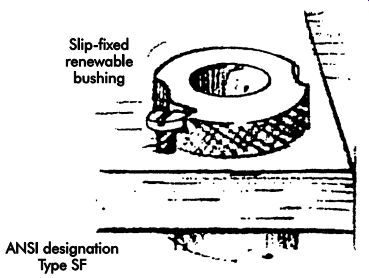
FIG. 36. Slip-fixed renewable bushing
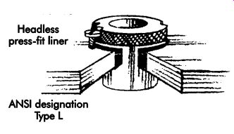
FIG. 37. Headless press-fit liner.
Headless Press-Fit Liners
ANSI designation Type L headless press-fit liners (FIG. 37) are used with slip-fixed renewable bushings to provide precise location.
They permit interchange of Type SF bushings with varied inside diameters, without affecting centerline accuracy. Type L liners are permanently pressed into the jig plate for the life of the jig, and protect the jig plate hole from wear caused by frequent bushing replacement. These liners are used where little impact will occur to bushing heads.
Headed Press-fit Liners
ANSI designation Type HL headed press fit liners (FIG. 38) are similar to headless press-fit liners but have a head or shoulder. They are used with slip-fixed renewable bushings whenever excessive pounding will occur during operation. The head prevents the liner from being pushed through. Type HL liners are mounted by counter-boring the top of the hole in the jig plate.
They are available with finish-ground outside diameters or unground for custom grinding.
Oil-groove Bushings
Oil-groove bushings are designed to provide complete lubrication between the cutting tool and bushing when maximum cooling is required during a machining operation. Over 24 separate groove pat terns on the inside diameter (ID) are available.
ANSI designation Type OG (FIG. 39) is used for drill lubrication or as a bearing. Lubricant (or coolant) flows through the grooves in the bushing's ID wall. Headless or headed styles are available. Although wiper designs help guard against dirt or chips, the oil groove should not break out the wiper end of the bushing.
Gun-drill Bushings
ANSI designation Type GD gun-drill bushings (FIG. 40) are used where maximum precision, long, deep holes are essential. Types GDB and GDX are of single-piece construction. The other type of gun-drill bushing is of two-piece construction. It consists of a liner (GDL) and an insert (GDI). The insert can be removed from the liner, thus allowing for a range of ID sizes using the same liner.
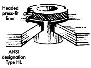
FIG. 38. Headed press-fit liner.
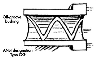
FIG. 39. Oil-groove bushings.
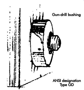
FIG. 40. Gun-drill bushing.
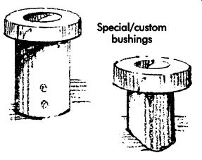
FIG. 41. Special bushings.
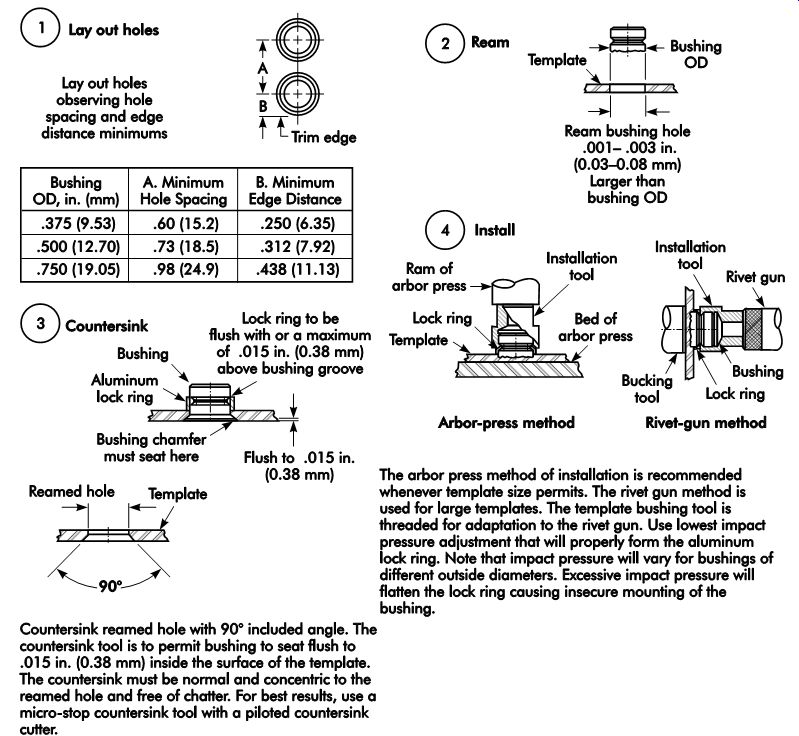
FIG. 42. Installing template bushings.
Special Bushings
Modified standard and custom bushings (Fig. 41) are also available.
The modified standard bushing begins with an ANSI standard bushing, which is altered in its ID, OD, or length.
Custom bushings cannot be easily modified.
Customizable elements include diameters, shapes, angles, materials, threads, etc.
Bushings and liners for Polymer, Castable, and soft Material tooling
Some bushing types have serrated or grooved ODs for casting in place with epoxy resins, thermoplastic tooling compounds, or low-melt alloys. Another type is used for press-in installation in soft materials, such as aluminum, magnesium, wood, or masonite. One particular liner type serves the same function as the type UL, except that it is knurled for use in plastic tooling.
Template Bushings
Template bushings (Type TB) are used with thin template materials ranging from .063-.375 in. (1.60-9.53-mm) thick to provide low-cost tooling. Installation is shown in FIG. 42.
Rotary Bushings
Rotary bushings feature precision-tapered roller or ball bearings capable of handling high thrust and/or radial loads encountered in some jig applications, such as supporting a piloted cutting tool for extremely close machining.
Drill Bushing tips and accessories
Drill bushing tips (see FIG. 43) are used with automatic self-feed drill motors. Most are constructed of two pieces consisting of a lock flange and a collar, which contains the screw threads and alignment diameter. It also features a pressed-in shank, which is a plain bushing with an ID ground to guide and support the cutting tool, and an OD ground to suit the liner bushing mounted on the jig.
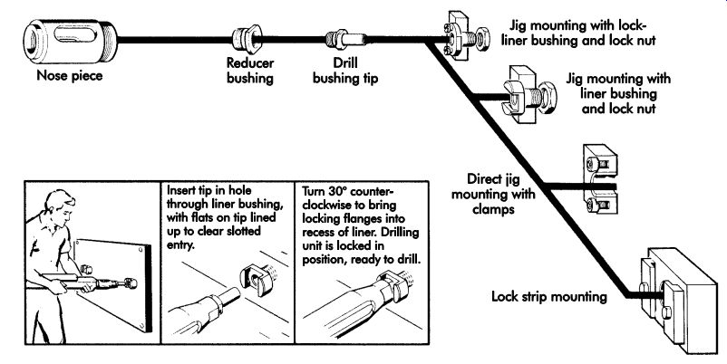
FIG. 43. Drill bushing tips.
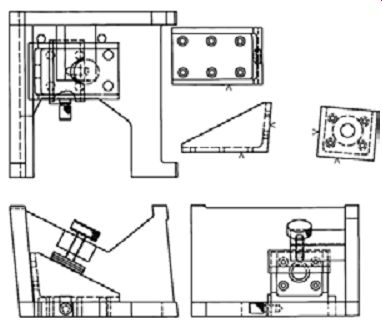
FIG. 44. Preliminary jig design.
Jig design example

TBL. 1. Considerations for jig design.
The most efficient method of designing any jig is to follow a systematic approach. FIG. 44 shows a part with which such an approach is used. The considerations and their effects for a jig design (TBL. 1) are intended to illustrate the step-by step process before determining a final jig design.
The information in TBL. 1 is only meant as an example and not as a rule for all jigs. Just as each part has its peculiarities, each tool also has its own specific characteristics that must be addressed.
Each individual element of the jig must first be thought out and sketched. The elements are then brought together in a sketch of the complete tool. The following represents one method to systematically design a jig around the proposed workpiece.
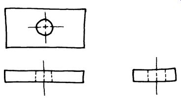
FIG. 45. Sketch of the part.
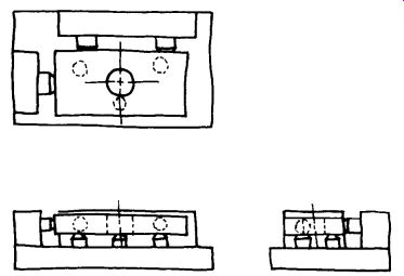
FIG. 46. Sketch in locators and supports.
The simplest and easiest way to begin a jig de sign is to sketch the part in three or more views (FIG. 45). The sketch should be made to a scaled size of the actual part, and the jig must be sketched to the same scale size. This sketch can be made manually. Make sure to allow sufficient room between each view to permit the remaining elements to be sketched without crowding. It is sometimes better to sketch the part in a different color, such as red, to allow it to stand out.
Once the part is sketched, the next step is to add the locators and supports (FIG. 46). Again, these details must be drawn to the proper scale and size. If commercial locating devices are specified, check a catalog to find the exact size of each area of the locator or support. Each locating element must be drawn as it would appear in each view. Many tooling suppliers provide computer aided design (CAD) files of their products, making the design process easier.
Next, the tool body should be added to the sketch. Since this element is an integral part of the entire tool, it should be drawn to the proper proportion and size. Once the part, locators, supports, and tool body are sketched, a thorough inspection must be made to ensure there is no interference between these elements. Look for areas where the elements are positioned close together. When constructed, these points could interfere with each other. Make sure the locator design will permit adequate space for chip and coolant removal. As a preliminary check, make sure there are no redundant locators and that the part can only be loaded correctly. Any location problem must be resolved before the clamping element is added to the jig.
Once the jig design has been checked and no conflicts between the elements exist, the clamping device can be added to the design (FIG. 47). When designing or selecting the clamping device, remember that this is the area of the tool that can either save or add time in production.
Always select clamping devices that are simple to use and fast operating. It is important to make sure that the clamps do not affect the part's surface in a negative way, especially those surfaces that are machined. Spending an additional hour in construction time to make a better clamp could easily save thousands of dollars in production costs. Once a clamp design is determined, it should be sketched into the existing drawing of the jig. Remember to include the clamping device in each view. With the clamp sketched in place, once again begin a thorough inspection of the design to ensure there is no conflict or interference between the various elements.
The next step in the initial design of the jig should be to add the drill bushings (FIG. 48). The location of these bushings is critical to the accuracy of the jig and they should be placed carefully. The tolerance values specified for the bushing placement should reflect a positional relationship of about 50% of the part tolerance. So, if a part dimension is specified as 1.000 in. ±.010 in. (25.40 mm ±0.25 mm), the bushing location should be specified as 1.000 in. ±.005 in. (25.40 mm ±0.13 mm). A general rule of 50% of the part tolerance applied to the tool will not only provide parts within the required accuracy, but also reduce the cost of constructing the jig since the tolerance value allows the toolmaker more space in which to place the bushings. In cases where extreme ac curacy or high-volume production tools must be made, a tight tolerance could easily nullify the cost effectiveness of the jig and result in a loss rather than an increase in profit from using the tool.
When selecting the bushings to use in the jig, always specify bushings that will permit adequate support for the cutting tool. If space is not a problem, use head-type bushings. If, however, space is limited, headless bushings should be used. In those cases where the bushings will be replaced frequently, either fixed-renewable or slip-renew able bushings should be specified. If these bushings are used, remember to include liner bushings.
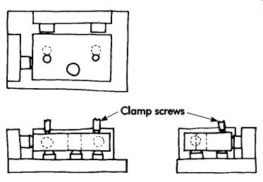
FIG. 47. Add the clamping device to the design.
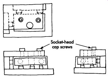
FIG. 48. Add the drill bushings.
Once the bushings are added to the sketch, check the complete tool once again to ensure the elements will not interfere with each other or the operation of the jig. At this stage, the clearance between the drill bushings must be determined. If clearance is desired, provisions should be made to ensure adequate space exists in the tool. If, however, no clearance is desired, the designer should make sure the jig plate and bushings will fit flush against the part.
The initial sketch of the basic jig is now complete; however, the relationship between the jig and the machine tool it is to be used with must now be checked. Using the size specifications for the machine tool selected for the operation, sketch the relationship between the jig and the machine table, spindle, and frame. Look for areas where any interference might occur. Sketch the proposed mounting device on the table to make sure the T-slots are the proper size. Or, in cases where strap clamps are used, make sure they will not interfere with the operation of the jig.
Determine if the specified cutting tool will per form the desired operation without interfering with the jig body or other elements. Check the clearance between the cutting tool and machine tool members. Always specify standard, off-the shelf cutting tools whenever possible. Do not modify a standard tool to accommodate a flaw in the jig design. It is simpler to alter the jig design than to justify the additional costs of modifying standard tools. All tooling problems must be resolved on the drawing board, not in the shop during production.
Once the initial sketches are complete and the designer is convinced the design is sound and workable, the final tool drawings are initiated.
Here again, the designer should look for any problem areas where the jig elements interfere with each other or the operation of the machine tool. In cases where the jig is to be used with numerically controlled or other automatic machinery, the designer should check the program to ensure the jig will not interfere with the operation of the machine tool. Look for points such as the height of the tool during the return or tool change cycle, or when moving from hole to hole. Make sure the actual height of the highest element of the jig is considered, not just the height of the jig plate. When manual machines are specified to use the jig, make sure the length of spindle travel is sufficient to permit easy use of the tool. Again, make sure the actual height of the tool will permit the jig to be easily moved under the spindle. Little would be saved if the table of the machine tool had to be lowered and raised to clear an obstruction or move the jig from hole to hole.
Plate Jig design example Using the methods previously outlined, the process of designing a plate jig for the part shown in FIG. 49 is as follows.
The first step is to inspect the part to deter mine the basic requirements and condition of the workpiece material. In this case, the requirement is for a jig to drill two .188-in. (4.78-mm) diameter holes in the locations shown in the figure. The part is 4.00 × 2.00 × .75 in. (101.6 × 50.8 × 19.1 mm) cold-drawn AISI 1030 barstock that weighs 1.71 lb (0.8 kg). The production plan calls for a one-time production run of 600 pieces, so the jig must be made as inexpensively as possible, yet the production rate must be rapid.
Next, sketch the part in three views as shown in FIG. 50. If the part is small enough, the sketch should be made full size. This permits the designer to see the full-size tool and eliminates any errors when converting to a scale size. Remember, it is often a good idea to sketch the part in a different color to allow it to stand out and to minimize the chance of misinterpreting the meaning of the lines in the sketch.
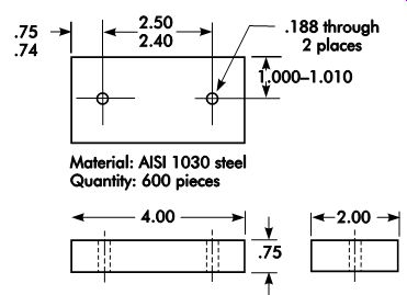
FIG. 49. Part to be designed.
Once the part is sketched, the locators should be positioned in the sketch (FIG. 51). Here, a simple 3-2-1, or six-point locational arrangement is used, since the part does not present any spacial locational problems. The three locators on the primary datum surface, in addition to establishing the location of this plane, also serve as risers to provide the necessary clearance between the drill bushings and the part. If a zero clearance is desired, the three locators on this surface can be eliminated and the part located against the flat jig plate. Secondary locators, positioned on the long side of the part, should be spaced about 3.00 in. (76.2 mm) apart to gain the maximum practical distance between them. The tertiary locator should be positioned approximately 1.50 in. (38.1 mm) from the secondary locators to find the end position of the part. The length of the secondary and tertiary locators is specified as 1.375 in. (34.93 mm). This will permit the accurate location of the workpiece and prevent the ends of the locators from interfering with the machine table while drilling the part. With the locators in place, the remainder of the tool body, or in this case, the jig plate, is sketched (FIG. 52). The thickness specified for this jig plate is .50 in. (12.7 mm). This thickness will accommodate the headless-press-fit bushings that are specified, and provide adequate support for the drill. If headed-press-fit bushings are specified, a thinner jig plate could be used.
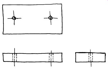
FIG. 50. Preliminary sketch.
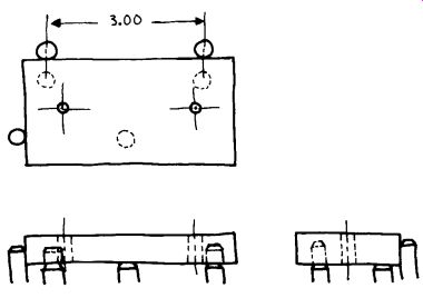
FIG. 51. Position the locators in the sketch.
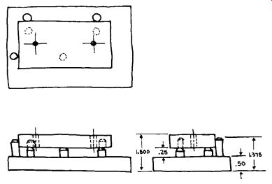
FIG. 52. Sketch in the jig plate.
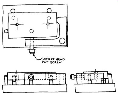
FIG. 53. The simplest and fastest clamp for this part is the L-shaped clamp.
The next step in the design of the jig is to add the clamping device. This type of plate jig can use several different clamping devices; however, the simplest and fastest-acting clamp would be an L-shaped clamp, as shown in FIG. 53. The clamp is mounted as shown and is activated by the screw in the long leg of the L. As the screw is tightened, the part is pressed against the secondary locators. At the same time, the short leg of the L presses against the part, forcing it against the tertiary locator. This type of locator may take a little longer to make than a simple screw clamp positioned at the side and end, but the faster operation of the clamp will more than offset the additional costs of its manufacture.
To add drill bushings to the design, the first step is to locate the bushings over the holes sketched in the part (FIG. 54). Next, the dimensions and tolerances of the bushing locations must be established using the 50% rule.
The initial sketch of the jig is now complete.
Since the holes are only .188 in. (4.78 mm) in diameter, the jig can be held by hand and does not require an additional holding device.
Likewise, since the jig is so small, there is little chance of its interfering with the operation of the machine tool, so the machine elements may or may not be sketched, depending on the desire of the designer. The final step in the design of this jig is to complete the final tool drawings.
Remember to look for any interferences that may have been overlooked in the sketch.
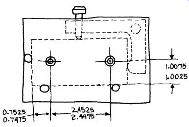
FIG. 54. Add drill bushings.
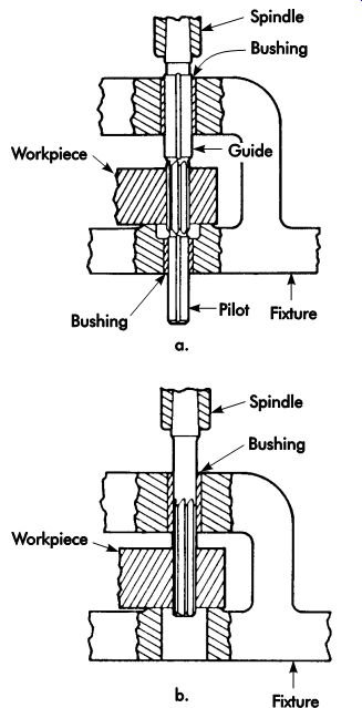
FIG. 55. Fixtures for guiding reamers.
Jig design for reaming
Jig design for reaming is basically the same as for drilling, which has been discussed throughout the section. The main difference is the need to hold closer tolerances on the jigs and bushings, and provide additional support to guide the reamer. For long holes, it is essential to guide the reamer at both ends, as shown in FIG. 55a, using special piloted reamers designed for this purpose. Jigs should be designed so the pilot enters the bushing before the reamer enters the workpiece, and it remains piloted until the reaming operation is completed. For short holes, the reamer is usually guided at one end only, as illustrated in FIG. 55b, with the bushing sized to fit the OD of the reamer. Additionally, bushings for reaming are generally longer than for drilling, usually three or four times the reamer's diameter.
Chip clearance is generally less for reaming than for drilling, varying from one-fourth to one-half of the tool's diameter down to a maximum of .125-.240 in. (3.18-6.10 mm), regardless of the reamer's diameter.
Bushing bores must be closely controlled.
Bushings that are too small can cause tool seizure and breakage. Bushings that are too large will result in bell-mouthed or out-of-round holes.
Carbide bushings should be considered for long production runs or when abrasive conditions are present. Roller or ball bearing, rotary type bushings also provide maximum wear while maintaining close tolerances under high loads.
Reference
Boyes, W. E. 1989. Handbook of Jig and Fixture Design, Second Ed. Dearborn, MI: Society of Manufacturing Engineers.
Other Refs.
The Society of Manufacturing Engineers (SME) has developed the Fundamentals of Tool Design video series, which comprises nine DVDs, of which one relates directly to this section's content: Fixture Design (19 minutes).
To correctly machine a part, it must be held in a fixturing setup that guarantees a definite location, or position, with respect to a part's datum points or surfaces. This must be repeatable, part after part. Fixture Design explores the various issues influencing the development of fixtures, as well as the basic fixture types and classifications, including milling fixtures, lathe fixtures, grinding fixtures, and broaching fixtures. The use of component kits to quickly build modular fixturing systems is also examined.
QUIZ
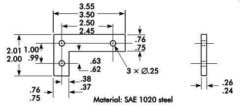
Figure A.
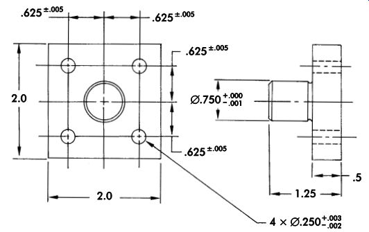
Figure B.
1. What are the two general classifications of jigs?
2. What are the two categories of jigs?
3. How does a table-plate jig differ from a plate jig?
4. What is the function of a drill bushing?
5. What is the solution when hole center distances are so close that there is not enough room for drill bushings?
6. What is the normal clearance between the bushing and workpiece for materials that produce small chips? Long chips?
7. In cases where a drill bushing is not used, how is the jig treated to guide the drill?
8. What is the simplest and easiest first step in designing a jig for the workpiece shown in Figure A?
9. Develop a preliminary design for a simple jig for the workpiece shown in Figure B for a nonrepeating run of 300 parts.
10. What type of bushing should be used in conjunction with a renewable bushing?
11. What are the main disadvantages of tem plate jigs?
12. List at least four advantages of a universal jig.
13. Why is it necessary to stress-relieve jig bodies that have been constructed by welding?
14. What is the value of using a universal/pump jig for the base rather than building a base?
15. Chips sometimes pass back through the drill bushings. What types of problems does this cause?
16. What is the purpose of the flop jig?
17. List two major disadvantages associated with the use of leaf jigs.
18. Drill jig bushings have been standardized in type and size. Describe the differences and functions of the following types:
a. headed press-fit bushing
b. headless press-fit bushing
c. fixed-renewable bushing
d. slip-renewable bushing
e. threaded bushing