AMAZON multi-meters discounts AMAZON oscilloscope discounts
(cont. from part 1)
Tool Drawings
A tool designer must have a strong background in engineering design graphics, dimensioning, and documentation and analysis of part drawings and specifications to properly present design concepts to the people who will make the pro posed tool. Often, computer-aided design (CAD) technology is used for this purpose. For the most part, toolmakers and die makers do not require the same type of drawings as do the less experienced machine operators in a production department. For this reason, tool drawings can be drawn much simpler and faster to keep design costs to a minimum. Following are useful points to remember when creating tool drawings.
• Strive to use American National Standards Institute/American Society of Mechanical Engineers (ANSI/ASME) standards, when possible.
• Draw and dimension with due consideration for the person who will use the drawing to make the item in the tool room.
• Do not crowd views or dimensions.
• Analyze each cut so that wherever possible the cut can be made with standard tools.
• Use only as many views as necessary to show all required detail.
• Surface roughness must be specified.
• Tolerances and fits peculiar to tools need special consideration. It is not economical to tolerance both details of a pair of mating parts as is required on production part detailing. In cases where a hole and a plug are on different details to be made and mated, the fit tolerance should be put on the male piece and the hole should carry a nominal size. This allows a toolmaker to ream the hole with a nominal size tool and grind the plug to fit it, although nominal may vary several thousandths of an inch (mm) from exact.
• The stock list of any tool drawing should indicate all sizes required to obtain the right amount for each component's detail. It is necessary to allow material for finishing in almost all cases, although some finished stock is available, which may meet design requirements. Whenever possible, stock sizes on hand should be used. However, in all cases, available sizes should be specified. A proper, finished detail is dependent upon starting with the right material.
• Use notes to convey ideas that cannot be communicated by conventional drawing. Heat treatments and finishes are usually identified as specification references rather than being spelled out on each drawing.
• Secondary operations, such as surface grinding, machining of edges, polishing, heat-treating, or similar specifications should be kept to a minimum. Only employ these operations when they are important to the overall function of the tool; otherwise, these operations will only add cost, not quality to the tool.
• Apply specific tolerances realistically. Overly tight tolerances can add a great deal of additional cost with little or no added value to the tool. The function of the design feature should determine the specific tolerance.
• If tooling is to be duplicated in whole or in part for other locations, or if multiple tools are required, drawings should be properly detailed to ensure uniformity.
Typical Tooling Layout Process
The actual work of creating the assembly design of equipment or tools for manufacturing processes should be done within the general framework of the following rules. This will en sure that the details of the tool will work and not interfere with any other part of the tool. These rules should be followed whether utilizing CAD or conventional techniques.
• Lay out the part in an identifying color (red is suggested) or phantom line font.
• Lay out the cutting tools. Possible interference or other confining items should be indicated in another identifying color (blue suggested). Use of the cutting tool should not damage the machine or the fixture.
• Indicate all locating requirements for the part. There are three locating planes-use three points in one, two points in the second, and only one point in the third. This is called the 3-2-1 locating system. Do not locate on a non-machined or rough part surface such as the parting line of castings or forgings. All locators must be accessible for the simple cleaning of chips and dirt.
• Indicate all clamping requirements for the part. Be careful to avoid marking or deforming finished or delicate surfaces. Consider the clamping movements of the operator so that injury to the hands and unsafe situations are eliminated. Make sure it is possible to load and unload the part.
• Lay out the details with due consideration of stock sizes to minimize machining requirements.
• Use full scale in the layout if possible.
• Indicate the use of standard fixture parts (shelf items) whenever possible.
• Identify each item or design detail by using balloons with leaders and arrows that point to the detail. These should not go to a line that is common to other details.
Safety
Safety laws vary greatly from one state to another. However, the Occupational Safety & Health Administration (OSHA) has regulations/laws governing operator safety. All states have some laws requiring protective guards and devices to safeguard workers.
Safety should be designed into the tooling.
One of the first and least expensive requirements should be that of breaking all sharp edges and corners. Both purchased tooling components and parts being manufactured require this process.
More minor injuries result from these items than most others.
Cutting should never be performed against a clamp because of vibration and tool chatter. In stead, parts should be nested against pins to take the cutter load. Rigidity and fool proofing should always be built into the tooling. Make drill jigs large enough to hold without the danger of spinning. Small drill jigs should always be clamped in a vise or against a bar or backstop. They should never be held with the operator's hands. Install Plexiglas guards around all milling and fly-cutting operations where chips endanger workers or work areas. High-speed open cutters on production milling, drilling, turning, and jig-boring machine tools are difficult to safeguard because of the varied size and location of the workpieces to be machined.
Punch Presses
In guarding punch presses, no single type of guard is practical for all operations. Ring guards work well on small punching setups where the ring meets an obstruction and the downward motion of the ram is stopped. Larger die sets and presses can be better protected by gate guards that must be positioned after the work is loaded and then interlocked with the clutch mechanism.
Barrier guards and light curtains protect workers by preventing hands and arms from being placed inside the work area during operation.
Generally, barrier guards are telescoping, perforated sheet-metal coverings with an opening to feed the stock, while light curtains are totally electronic, nonmechanical guards. Sweep guards actually sweep the danger area clear as the press ram descends, providing protection during an accidental descent of the ram. Wire-cage guards are still another way to protect the operator's hands (the operator feeds the work through a small opening). This type of guard is useful for secondary operations. Another method of protection is to provide a space between pinch points on the punches and dies that is too small for the operator's hand to enter; this distance should not exceed 3/8 in. (9.5 mm). Punch presses cause many injuries every year, so employers should place special emphasis on safety when dealing with these machines.
Limit Switches
Limit switches can be used extensively to protect both worker and product. In punches and dies, limit switches can detect a misfeed or buckling of stock, and check the position of parts during assembly. Photoelectric equipment to protect the operator's hands or body operates when the set beam is interrupted. It is good practice for all punch presses and air or hydraulically operated tooling to be installed with a double button interlocking protection system, requiring both buttons to be activated before the tool can be used. Other interlocking systems can include two valves in conjunction with a hand valve designed to prevent the tooling or press from operating in case one of the buttons is locked in a closed position. The device should be located in such a position or guarded in such a manner that the operator cannot operate the tooling or press while in the danger area.
Feed Mechanisms
Feed mechanisms should be provided for all high-speed punching, machining, or assembling operations. The safety function of a feeding device is to provide a means of moving the part into the nest by gravity or mechanical action so there is no necessity for the operator to place his or her hands in the danger zone. High-speed presses equipped with automatic feeds operate at such speeds that it would be impractical, as well as hazardous, for an operator to attempt to feed the stock.
Electrical Equipment
Tools and additions to machinery involving electrical equipment must be grounded. Portable electrical equipment should be checked periodically because of rough handling, and all equipment should be grounded to prevent injuries to personnel. Locks, which hold electrical switches open while tools or punches and dies are being repaired or set, help prevent accidental dam age. Local regulations can be found in each state's electrical code book covering all applications.
Other Considerations
Tooling for various industries requires different treatment to ensure safe operations. For example, special electrical controls and motors are required for industries handling explosive material. Tooling material for the chemical industry should be designed to withstand corrosive actions, and electrical equipment should be properly sealed. Careful analysis must be given to tooling for each type of application to provide maximum protection and long life.
Machining various plastics sometimes generates abrasive dust particles or poisonous fumes.
In such cases, exhaust systems are required.
Likewise, safety procedures should be practiced when handling certain metals. Nickel dust is a suspected carcinogen, and dust from beryllium alloys and compounds can cause chronic beryllium disease. Areas around magnesium machining should be kept clean and tools kept sharp to reduce fire hazard. Metal powders present a hazard of combustion during grinding operations.
Data can be found in chemical, electrical, and industrial handbooks to help in designing tooling for these special materials.
Tooling and additions to machines must be de signed so that the operator does not have to lean across a moving cutter or table. All adjustments and clamping should be easily accessible from the front or the operator's position. Consider body geometry when designing tooling-in terms of not only safety, but also production. Good ergonomic principles should always be applied.
Tooling involving welding must be guarded to prevent severe burns or eye injury from high-intensity, arc-welding rays. Safety glasses should be worn during all machining, grinding, and buffing operations. Welding curtains, proper ventilation, and efficient workstation layout should be considered as well.
All belts, chain drives, gears, sprockets, couplings, keys, and pulleys should be totally guarded by sheet metal and panel guards. Guards should be strong enough to support and protect workers in the event that someone or something falls against the guard, or in case the belt or chain should break. Always provide an adequate factor of safety in the design of all tools and tooling applications.
Safety standards are available for all types of industrial applications. Personnel who are responsible for plant safety should be familiar with them. Some of the agencies handling such information are: American National Standards Institute (ANSI); National Institute of Standards and Technology (NIST); U.S. Department of Commerce; National Safety Council; National Fire Protection Association (NFPA); American Insurance Association; and the Occupational Safety & Health Administration (OSHA).
Safety is of the utmost concern when a production tool involves several complex operating mechanisms. Tooling is not restricted solely to machining operations. Automatic assembly and inserting equipment may be classified as either a tool or a machine. Complex tools might contain any combination of electric motors, air cylinders, hydraulic equipment, conveyors, and precision indexing tables.
Material Handling in the Workplace
It is beyond the scope of this text to detail the bulk handling of materials and parts through the factory or the many principles that underlie workplace design. Full texts are devoted to this area. It is the objective of this brief discussion to emphasize the important role that tool design plays in the total cost of an operation from the standpoint of material handling.
To pick up a workpiece, place it into a tool, clamp the part, unclamp it, remove it, and set it aside after machining may consume more time than the actual machining. Such operations, however essential, contribute nothing of value to the product, but their performance is paid for at the same rate as the productive effort. Consequently, tooling should be designed to reduce nonproductive time and costs.
Once a tool is designed and built, the methods of handling materials into and out of it are fixed. It is essential then to plan the methods of material handling carefully. The following two sections detail the principles that should be applied to help ensure maximum motion economies.
Arrangement and Conditions of the Workplace
The following tips are presented to assist in the development of a satisfactory work environment.
• Obtain relevant information on task performance, equipment, working posture, and environment through direct observation, video recording, and/or input from experienced personnel.
• Identify the appropriate user population and obtain the relevant anthropometric measurements or use the available statistical data from anthropometric surveys.
• Determine the range of work height based on the type of work to be performed. Provide an adjustable chair and a footrest for a seated operator, and an adjustable work surface or platform for a standing operator.
• Lay out the frequently used hand tools, controls, and bins within the normal reach space. Failing that, they may be placed within the maximum reach space. Locate the control or handle in the most advantageous position if strength is required to operate it.
• Provide adequate elbow room and clearance at waist level for free movement.
• Locate displays within the normal line of sight.
• Consider the material and information flow requirements from other functional units or employees.
• Make a scaled layout drawing of the pro posed workstation to check the placement of individual components.
• Develop a mock-up of the design and con duct trials with live subjects to ascertain operator-workstation fit. Obtain feedback from these groups.
• Construct a prototype workstation based on the final design.
Design of Hand Tools
In the article, "Hand Tool Design," Susan Nemeth provides 10 principles for the design and use of hand tools. These principles help prevent injuries and enhance the performance and quality of workmanship. The principles discuss tool design and tool use, along with workstation and job designs. This is consistent with the systems-type approach followed in this book. The principles and brief comments are discussed in the following paragraphs.
Maintain straight wrists. Bent wrists encourage carpal tunnel syndrome. Any wrist deviation is further aggravated by repetitive motions or large forces. The tool should be held and used in a neutral position.
Avoid static muscle loading. The work should be done with the arm and shoulder in a normal position to avoid excessive fatigue. This is especially true when tool weights are large or the tool is used for extended periods of time. Counterbalancing tools is a common solution.
Avoid stress concentrations over the soft tissue of the hand. Pressure on these tissues can obstruct blood flow and nerve function.
Reduce grip force requirements. Grip forces can pressure the hands or result in tool slippage.
Of special note is the distribution of force on the hand, which results in the same problems mentioned in avoiding stress concentrations.
Maintain optimal grip span. The optimal power grip with the fingers, palm, and thumb should span 2.5-3.5 in. (63.5-88.9 mm). For circular tool handles, such as screwdrivers, the optimum power grip is 1.25-2 in. (31.75-50.8 mm). For fingertip use, the optimum precision grip is .3-.6 in. (7.62-15.24 mm).
Avoid sharp edges, pinch points, and awkward movements. Sharp edges cause blisters and pres sure points. Pinch points can make a tool almost unusable. Awkward movements are easily found through observation or use. The movement required to open a tool is a common problem, especially when used repetitively.
Avoid repetitive finger trigger actions. Using a single finger to operate a trigger is harmful, especially with frequent use. Use of the thumb is preferred, since the thumb muscles are in the hand, not in the forearm (this avoids carpal tunnel syndrome). Other triggering mechanisms, such as proximity or pressure switches, are possible. Note, however, that the thumb can lock up and have similar ergonomic pain, but from different sources.
Protect hands from heat and cold. Like soldering irons and other heat-generating tools, tools with motors can produce and transfer heat. Cold comes most often from air-powered tools with an exhaust near the hand grips.
Avoid excessive vibration. Vibrations cause Reynaud's syndrome, or dead fingers. The best solutions are damping or isolating the vibration, although rotating jobs is a possible way to limit exposure.
Use gloves that fit. Gloves that are too big or thick reduce tool control because they reduce an individual's strength and dexterity. The most economical remedies are using gloves that are the correct weight for the job and stocking gloves in several sizes.
Tool Designer's Guide to Machine Tools
Tool designers are confronted with an array of over 150 different types of machine tools. Thus they are responsible for understanding the complexity of the machining processes related to metal removal. Fortunately, all conventional metal cutting processes rely on only three basic operations. But, other processes need to be understood as well.
Casting for forging production operations has some major limitations for providing dimensional precision and precise surface quality. Convention al machining will most likely be used to provide these attributes.
Metal can be removed by numerous other methods. Many are limited to their specific applications and are often difficult to employ as they require skillful setup and operation. These chipless processes include: electrochemical ma chining (ECM), electrical discharge machining (EDM), and grinding.
Electrochemical machining is a rapid depleting operation generally used to machine hard alloys. Electrical discharge machining is based on electrical spark erosion and is more widely used, especially in tool and die work. Grinding removes metal via abrasion and is generally used to shave off the last tenths of thousands of an inch to attain a finer surface finish, or for machining hardened metals.
Terminology Defined
Metal-cutting machinery concepts are much easier to understand when basic terminology is defined. All metal-cutting machines (drill presses, milling machines, etc.) utilize cutting tools that actually shave the metal. The entire machine itself is often referred to as a tool, as in the term machine tool. The fixtures (workholding devices) or jigs (guiding devices) used in conjunction with machine tools are generally referred to as tooling.
Taxonomy of machining processes
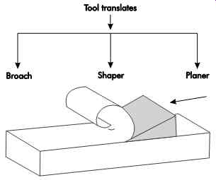
Figure 5. Tool translation used for broaches, shapers, and planers.
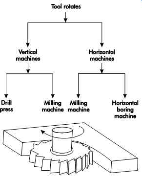
Figure 6. Tool rotation used with vertical and horizontal machine tools.
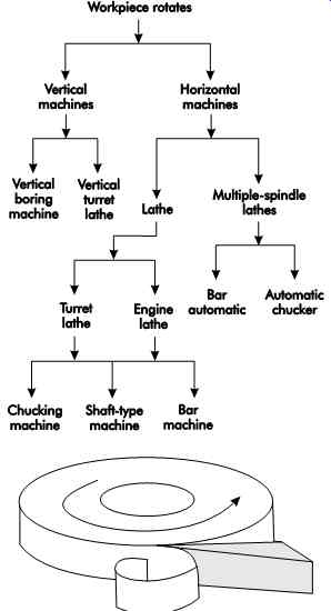
Figure 7: Workpiece rotation used with vertical and
horizontal machine tools.
Figures 5, 6, and 7 are intended to help form a conceptual taxonomy of machining processes as they relate to machine tools.
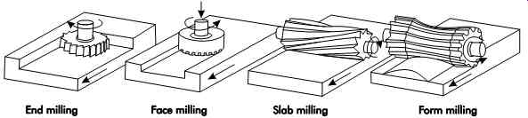
Figure 8: Operations for end, face, slab, and form milling.
As shown in Figure 8, a variety of cutting tools are used for milling operations. End milling requires a flat-bottom tool with teeth around its circumference. Face milling requires a tool with cutting surfaces on the end. Slab milling tools span the entire part surface in one pass. Special ground cutters are used for form milling.
During the shaping process (see Figure 9), a moving tool translates over a stationary work piece. Planing differs in that the tool remains stationary while the workpiece translates.
Broaching is essentially a filing operation, except that the cutting teeth produce increasing cutting action as the relation between the broach and part progresses.
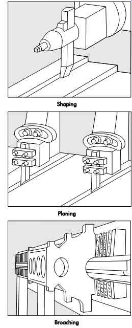
Figure 9. Translation operations for shaping, planing, and broaching.
QUIZ
1. Define the main objective of tool design.
2. Why are economical lot sizes calculated?
3. Why are breakeven charts used in tool de sign?
4. List four points where safety should be de signed into the tooling.
5. How are material handling and tool design related?
6. Define the first step in the design of any tool.
7. List three pieces of data used to identify the initial design.
8. List at least five ideas used in the development of a satisfactory work environment.
9. What are the 10 principles for the design and use of hand tools?
10. Manufacturing costs are divided into three major groups. What are they? Give at least three examples of each of the three major groups.
11. Why are the standard details or tool components used whenever possible?
12. Why should all hand and arm manipulations by the operator be performed on the operator's side of the jig or fixture?