Tool design is a specialized area of manufacturing engineering comprising the analysis, planning, design, construction, and application of tools, methods, and procedures necessary to in crease manufacturing productivity. To carry out these responsibilities, tool designers must have a working knowledge of machine shop practices, tool-making procedures, machine tool design, and manufacturing procedures and methods, as well as the more conventional engineering disciplines of planning, designing, engineering graphics and drawing, and cost analysis.
Design Objectives
The main objective of tool design is to increase production while maintaining quality and lowering costs. To this end, the tool de signer must:
• Reduce the overall cost to manufacture a product by making acceptable parts at the lowest cost.
• Increase the production rate by designing tools to produce parts as quickly as possible.
• Maintain quality by designing tools to consistently produce parts with the required precision.
• Reduce the cost of special tooling by making every design as cost-effective and efficient as possible.
• Design tools to be safe and easy to operate.
Every design must be created with these objectives in mind. No matter how well a tool functions or produces parts, if it costs more to make the tool than it saves in production, its usefulness is questionable. Likewise, if a tool cannot maintain the desired degree of repeatability from one part to the next, it is of no value in production. The following questions should be used as a checklist to determine if a particular tool design will meet the preceding objectives:
• Does the design require the operator to work close to revolving tools?
• Does the tool have a means to secure it to the machine table?
• Will the fixture keys fit the table of the in tended machine?
• Will the tool perform with a high degree of repeatability?
• Has every possible detail been studied to protect the operator from injury?
• Are all sharp edges and burrs removed?
• Is there any possibility of the clamp loosening or the work being pulled from the tool?
• Have the human ergonomics been considered in the design?
• Will coolants and cutting fluids freely drain from the tool?
• Is the tool easy to clean?
• Are coolant flow and chips directed away from the operator?
• Are loose parts attached with a cable or secured safely?
• Is the tool easy for the operator to load and unload?
• Can the tool be loaded and unloaded quickly and safely?
• Is enough leverage allowed for hand-held jigs?
Tool Designer Responsibilities
Typically, tool designers are responsible for creating a wide variety of special tools. Whether these tools are an end product or merely an aid to manufacturing, the tool designer must be familiar with:
• cutting tools, tool holders, and cutting fluids;
• machine tools, including modified or special types;
• jigs and fixtures;
• gages and measuring instruments;
• dies for sheet-metal cutting and forming;
• dies for forging, upsetting, cold finishing, and extrusion, and
• fixtures and accessories for welding, riveting, and other mechanical fastening.
In addition, the tool designer must be familiar with other engineering disciplines, such as metallurgy, electronics, computers, and machine design as they too affect the design of tools.
In most cases, the size of the employer or the type of product will determine the exact duties of each designer. Larger companies with several product lines may employ many tool designers.
In this situation, each designer may have an area of specialization, such as die design, jig and fixture design, or gage design. In smaller companies, however, one tool designer may have to do all of the tool designs, as well as other tasks in manufacturing.
The Design Process
While the specifics of designing each type of tool are discussed in subsequent sections of this text, a few basic principles and procedures are introduced here. The design process consists of five basic steps:
1. statement and analysis of the problem;
2. analysis of the requirements;
3. development of initial ideas;
4. development of possible design alternatives, and
5. finalization of design ideas.
While these five steps are separated for this discussion, in practice, each overlaps the others. For example, when stating the problem, the requirements also must be kept in mind to properly define and determine the problem or task to be performed. Likewise, when determining the initial design ideas, the alternative designs are also developed. So, like many other aspects of manufacturing, tool design is actually an ongoing process of creative problem solving.
Statement of the Problem
The first step in the design of any tool is to define the problem or objective as it exists with out tooling. This may simply be an assessment of what the proposed tool is expected to do, such as drill four holes. Or, it may be an actual problem encountered in production where tooling may be beneficial, such as where low-volume production is needed to relieve a bottleneck in assembly. Once the extent of the problem has been determined, the problem can be analyzed and resolved by following the remaining steps of the design process.
Analysis of Requirements
After the problem has been isolated, the requirements, including function, production requirements, quality, cost, due date, and other related specifics can be used to determine the parameters within which the designer must work.
Every tool that is designed must:
• perform specific functions;
• meet certain minimum precision requirements;
• keep costs to a minimum;
• be available when the production schedule requires it;
• be operated safely;
• meet various other requirements such as adaptability to the machine on which it is to be used, and
• have an acceptable working life.
Table 1 illustrates a method of applying these criteria to the process of choosing a tool design.
Rarely, if ever, will one tool design be best in all areas. The tool designer's task in this situation is to weigh all the factors and select the tool that best meets the criteria and the task to be performed.
Development of initial ideas
Initial design ideas are normally conceived after an examination of the preliminary data.
This data consists of the part print, process sheet, engineering notes, production schedules, and other related information. While evaluating this information, the designer should take notes to ensure nothing is forgotten during the initial evaluation. If the designer needs more information than that furnished with the design pack age, the planner responsible for the tool request should be consulted. In many cases, the designer and planner work together in a team environment to develop the initial design parameters.
Development of Design Alternatives
During the initial concept phase of design, many ideas will occur to the designer and/or the team. As these ideas are developed, they should be written down so they are not lost or forgotten. There are always several ways to do any job. As each method is developed and analyzed, the information should be added to the list shown in Table 1.
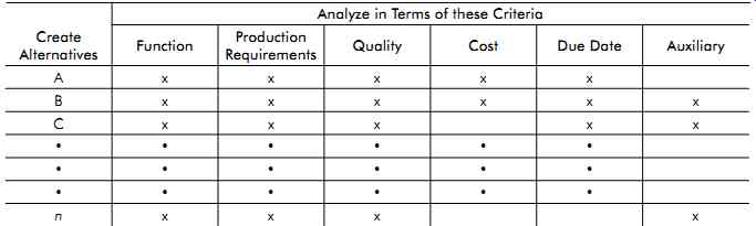
Table 1. Basic pattern for tool analysis
Finalization of Design Ideas
Once the initial design ideas and alternatives are determined, the tool designer must analyze each element to determine the best way to proceed toward the final tool design. As stated earlier, rarely is one tool alternative a clear favorite.
Rather, the tool designer must evaluate the strong points of each alternative and weigh them against the weak points of the design. For instance, one tool design may have a high production rate, but the cost of the tool may be very high. On the other hand, a second tool may have a medium production rate and will cost much less to build. In this case, the value of production over cost must be evaluated to determine the best design for the job.
If the job is a long-term production run, the first tool may pay for itself in increased production volume. If, however, the production run is short or it is a one-time run, the second tool may work best by sacrificing production speed for reduced tool cost. The best design is usually a compromise between the basic criteria of function, production requirements, quality, cost, due date, and other requirements.
Economics of Design
The tool designer must know enough economics to determine, for example, whether temporary tooling would suffice even though funds are provided for more expensive permanent tooling.
He or she should be able to check the design plan well enough to initiate or defend a planning decision to write off the tooling on a single run as opposed to writing it off by distributing the cost against probable future reruns. The tool designer should have an opinion backed by economic proof of certain changes that would make optimum use of the tools.
Lastly, the following basic guidelines of economical design are important to keeping costs low while maintaining part quality:
• Keep all designs simple, functional, and uncomplicated.
• Use preformed commercial materials where possible.
• Always use standard pre-manufactured components.
• Reduce or eliminate unnecessary operations.
• Do not use overly tight, expensive tolerances.
• Simplify tool drawings and documentation.
Many aspects of manufacturing economics are outside the scope of this book, but excellent literature is available.
Combined Operations
Analysis may sometimes show that operations can be cost-effectively combined. Tooling costs, production costs, or both can thus be reduced.
Table 2 illustrates a case where the cost of combined tools was less than the total cost of the separate tools otherwise required.
Process
Cost Comparisons
During process planning, many possible methods of manufacturing may be reduced to a few based on alternate process steps, use of available equipment, or combined operations. Under these conditions, a comparison of costs for different tools and process steps may reveal a combination resulting in the lowest total cost per part.
Let:
Nt = total number of parts to be produced in a single run
Nb = number of parts for which the unit costs will be equal for each of two compared methods Y and Z (breakeven point)
Ty = total tool cost for method Y, $
Tz = total tool cost for method Z, $
Py = unit tool process cost for method Y, $
Pz = unit tool process cost for method Z, $
Cy, Cz = total unit cost for methods Y and Z
Then:
For example, the aircraft-flap nose rib shown in Figure 1 of .020 in. (0.51 mm) 2024-T Alclad was separately calculated to be formed by a hydropress, drop hammer, Marform , steel draw die, or hand-forming process. For reasons such as die life, available equipment, and handwork required, the choice was narrowed down to the hydropress versus the steel draw die. With the hydropress, the flanges had to be fluted, and for piece quantities over 100, a more expensive steel die costing $202 had to be used.
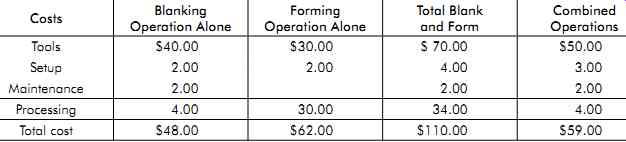
Table 2. Cost of combined versus separate operations
Actual die and processing costs for both methods are listed in Table 3. Py and Pz are processing costs, and Ty and Tz are die costs for the steel draw die and hydropress methods, respectively.
Figures in the last column of Table 3 were not stated in the original report, but can be properly extrapolated on the basis of the apparent stability of Py and Pz at Nt = 500, and assuming their stability at higher production rates.
On the basis of the listed figures at Nt = 500, and from Equation 1, the production at which total unit costs Cy and Cz will be the same for both methods is:
As an alternate method for calculating the breakeven point between two machines (for example, a turret lathe and an automatic), a formula based on known or estimated elements that make up production costs can be used. The breakeven-point equation is, ( 3) where:
Q = quantity of pieces at breakeven point p = number of pieces produced per hour
by the first machine
P = number of pieces produced per hour by the second machine
S = setup time required on the second machine, hours
L = labor rate for the second machine,
D = hourly depreciation rate for the second machine (based on machine-hours for the base period),
s = setup time required on the first machine, hours
l = labor rate for the first machine,
d = hourly depreciation rate for the first machine (based on machine-hours for the base period),
For example, assume it is desired to find value Q when the various factors are as follows:
p = 10 pieces per hour
P = 30 pieces per hour
S = 6 hours
L = $1.50 per hour
D = $1.175 per machine-hour
s = 2 hours
l = $1.50 per hour
d = $0.40 per machine-hour (10-year period)
Then, substituting these values in the equation,
Q Pp SL SD sl sd
or the quantity on which the cost is the same for either machine.
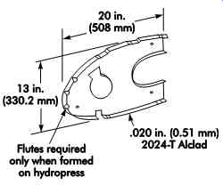
Figure 1. General specifications for aircraft-flap nose rib.
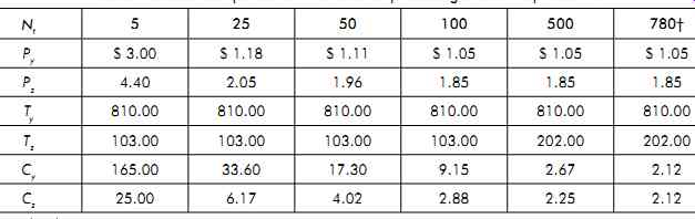
Table 3. Cost comparison of methods for producing aircraft-flap nose rib
effect of Tool material
Choice on Tool Life
The tool designer can often influence the choice of cutting-tool materials. Therefore, the tool designer must know the tool-life economics involved.
Typical tool-life curves are shown in Figure 2 for high-speed steel (HSS), sintered carbide, and oxide tools. The wear characteristics, as denoted by the n values, show that the economic life Tc for carbide tools is shorter than that for HSS tools (Tc equals 15 minutes for carbide versus 35 minutes for HSS). It is even more important to use higher speeds and a shorter tool life for oxide tools, since Tc equals five minutes.
In Figure 3 it is evident that most economical metal removal demands high cutting speeds and thus higher horsepower when using carbide and oxide tooling.
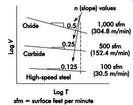
Figure 2. Tool-life comparison of various tool materials.
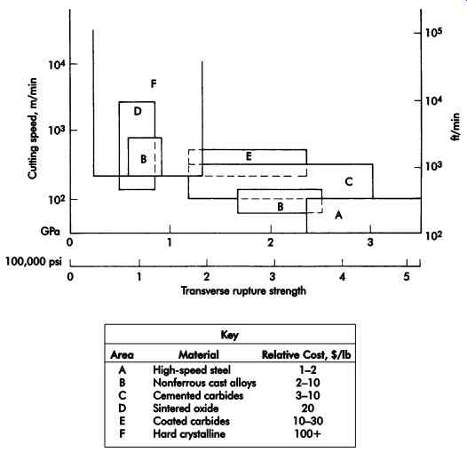
Figure 3. Performance data for various tool materials.
Economical Lot Sizes
Economical lot sizes are calculated to obtain the minimum unit cost of a given part or material. This minimum is reached when the costs of planning, ordering, setting up, handling, and tooling equal the costs of storage for finished parts. These costs may be equated and the lot size determined by mathematical calculation. De pending on the number of variables to consider, the equation can range from simple to complex.
By assuming that the number of pieces required per month is a constant, the inventory increases until the lot ordered is completely sent to stock, and decreases uniformly with use.
A relatively simple equation for calculation of economic lot size can be devised:
[eqn coming soon] (1)
where:
L = lot size, pieces
m = monthly consumption, pieces
S = setup cost per lot,
k = annual carrying charge per dollar of inventory,
c = value of each piece,
v = ratio of machining time to lot sizes, months per piece
Labor, material, and other costs not related to lot size are omitted. In practice, reasonable values for S, m, and c are difficult to obtain. These values are generally determined by the standards, sales, or methods departments.
Equations for calculating economic lot sizes can never be proven exactly because of the assumptions upon which many of the factors are based. Such an equation should be regarded as just a useful guide, to be applied with mature judgment.