Since computer numerically controlled (CNC) machining centers can perform many operations, such as milling, drilling, tapping, turning, and boring, fixtures must be designed for each of these operations. The cutter must be accessible to all surfaces of the workpiece that need machining operations, as shown in FIG. 1.
The closer a clamp is placed to a machined feature, the more the machining operation is restricted. Clamping can affect the tool diameter, cycle time, finish, and accuracy. Probably the most important objective is to keep the fixture and clamping to a low profile to prevent interference with the ideal programmed pattern for the cutting tool. The programmer must raise the tool above the clamp, move it over the clamp, and then drop it back down before resuming a cut ting operation. Keeping the clamping as low as possible reduces the amount of travel required to jump over the clamp, which results in cycle-time savings. Also, it permits the tool to be chucked as short as possible.
Accuracy
Most CNC machining centers are capable of holding extremely close tolerances, especially where all machining can be done with the same setup. For example, a machine may position to within .0005 in. (0.013 mm) of the programmed coordinates and return to the same position (repeatability) over and over within half that amount, or ±.00025 in. (±0.0065 mm). Fixtures for CNC have an equal role in transferring this accuracy to the workpiece. Closer tolerances increase the cost of a fixture. However, such fixtures can deliver a more accurate, consistent product.
Particular attention should be paid to flatness and parallelism when designing fixtures for CNC. FIG. 2 illustrates the effect on an 18.00-in. (45.7-cm) workpiece when held between vice jaws misaligned a total of .003 in. (0.08 mm). If a slot were milled down the center, it would be out of parallel by .009 in. (0.23 mm) in relation to the previously machined clamp surfaces. This could be enough to scrap the workpiece.
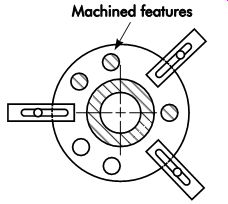
FIG. 1. Cutter accessibility.
Rigidity
Accuracy, surface finish, and productivity are affected by rigidity. Cutting tools produce severe shock, pressure, and vibration on the workpiece, which must be alleviated by good fixturing.
At least one or two solid surfaces should be de signed into the fixture, as shown in FIG. 3, to take the shock of the cutting tool. Clamps should be strong enough to hold the workpiece securely without distorting it.
Speed and Ease of Workpiece Changing
The tool designer must consider loading and unloading the workpiece. Usually, the lot size and total quantity of parts to be machined will dictate the amount of money that can be spent on the fixture. Using standard fixture components can lower the build cost substantially.
In many cases, a simple clamp will work fine. This type of clamp can be manually guided when close positioning is required. Many of the more sophisticated mechanical, pneumatic, and hydraulic clamping systems also can be used.
These clamps move out of the way when released and permit easy removal of the workpiece. The fluid-operated systems provide the additional advantage of being activated jointly by a single lever, button, or programmed sequence from a programmable logic controller (PLC) device.
Modular Tooling Systems
Dedicated fixtures for each workpiece are not desired. As for storing large quantities of dedicated fixtures for possible reuse in the future, there is no practical solution. Either they are scrapped out and new ones are built as needed, or they are stored in space that could be better used for producing parts. Modular tooling systems were designed to solve both of these problems at the same time. These systems are called by other names, but regardless of the name, they are all kits of tooling components that can be used together in various combinations to locate and clamp workpieces for machining, assembly, and inspection operations.
The components of a typical starter kit are illustrated in FIG. 4. A kit consists of mounting plates, angle plates, locators, clamps, and mounting accessories. Adapters also are available to permit the use of many standard and power-workholding devices. The method of assembling these components varies between systems.
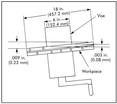
FIG. 2. Angular misalignment.
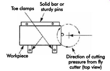
FIG. 3. Rigidity in tool design.
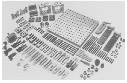
FIG. 4. Starter kit of modular fixturing components.
Fixtures made from modular tooling kits can be used on standard machines and numerically controlled (NC) machines as well as CNC ma chining centers. They can be positioned on U.S. or metric machine tables.
Modular tooling systems are valuable when con fronted with a short lead time or small production quantities that do not warrant the design and construction of a special jig or fixture.
Construction
The first step in assembling a jig or fixture is to select a base large enough to handle the work piece. Next, the main structure is constructed with riser blocks and reinforced with stop-thrust elements. Finally, the more specialized elements are added to properly locate and clamp the work piece for machining.
FIG. 5 shows an erector-set fixture; FIG. 6 shows the fixture with a workpiece in place.
An ideal method of constructing a jig or fixture with a modular tooling kit is to build it around a sample part. Simply position the sample part on the base and add locators, supports, and clamps as needed. This method reduces the construction time to a fraction of what it would take to design and build a dedicated jig or fixture to do the same job. The use of a sample part also can expedite frequent assembly and disassembly of jigs and fixtures.
When no sample part is available, a jig or fixture can be assembled around a template of the part.
Templates also are useful to check for interference that could occur when loading or unloading parts.
Machining on Modular Fixtures
Jigs and fixtures assembled from modular tooling seldom need machining. Occasionally, limited machining may be required to produce a special component. Excessive machining, however, should always be avoided, since it will eliminate the economic advantages of the system.
If, for some reason, the jig or fixture is impossible to construct without considerable machining, modular tooling should not be used.
The Tool Assembler/Maker
Even though modular tooling is easily assembled, the need for tooling knowledge and experience is not diminished. Jigs and fixtures constructed with modular tooling kits must be strong enough to withstand the machining forces imposed on them, built to use adjustable components, and often must accommodate an in-process part. The tool assembler/maker must have the imagination and experience to foresee potential problems and plan accordingly. The selection of a tool assembler requires careful consideration.
Pallet/Fixture Changers
The prevalence of just-in-time (JIT) production methods has made smaller lot sizes necessary and, consequently, more frequent changeover is required. The result is machines that may sit idle 30-40% of the time.
Idle time has led to the use of manual pallet/fix ture changers in vertical machining centers. One pallet slides or shuttles away from the spindle to allow offline loading, unloading, cleaning, and setup work, while the machine continues making parts on another pallet (FIG. 7). This process is effective on small or large lot sizes and allows changeover in less than one minute.
The operator then is free to spend more time inspecting work while parts are being produced.
New machining centers are now outfitted with pallet/fixture changers as standard equipment.
Advantages of Modular Tooling Reduced Lead Time
Reduced lead time is the major advantage of a modular tooling system. Jigs and fixtures usually can be assembled in a few hours' time with readily available components, virtually eliminating lead time. Tooling often can be assembled in less time than it takes to prepare a tool-path program for the part.
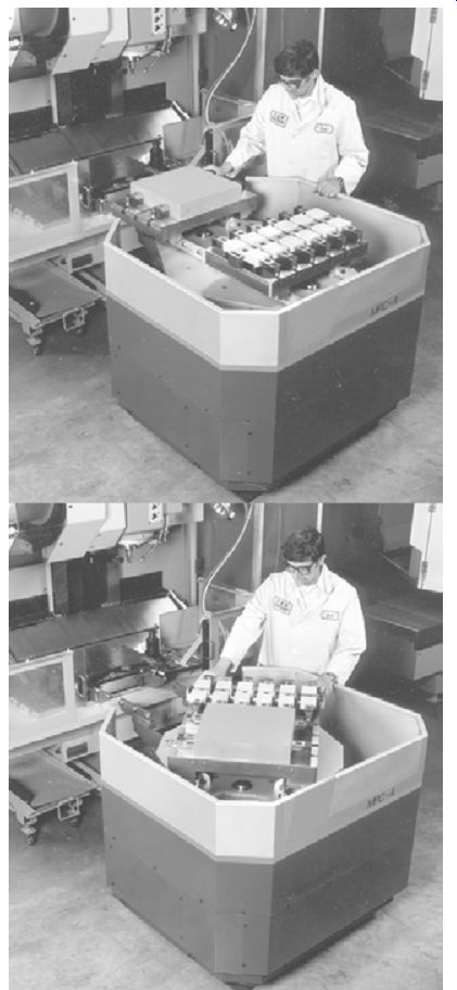
FIG. 7. Pallet changer.
Adaptability
Tooling changes to accommodate new products, or revisions to existing products, are fast and easy with modular tooling. For companies experiencing frequent product changes, new products will not be held up waiting for changeover, since changes to existing tooling can be made immediately without interrupting production.
Sometimes, tool trials show the need for revisions that are difficult and time-consuming to make on a dedicated fixture. These changes can be made easily and quickly with modular tooling.
Even when a dedicated fixture is planned, modular tooling can be used to establish the basic design and tool clearances.
Reusability
Although modular tooling kits may seem ex pensive, they usually pay for themselves in one to two years. At the completion of a production run, the modular jig or fixture can be completely dismantled and the components returned to the kit for reuse, whereas conventional tooling is usually stripped of any reusable parts and then scrapped for a fraction of its original cost. An example of this is shown in FIG. 8. The fixture on the left will be useless at the end of the production run, whereas the modular fixture
will be completely torn down and the components returned to the kit for reuse. Storage of the dedicated fixture for possible revision and reuse at a later date may be considered, but storage costs, when added to revision costs, usually make this an expensive proposition.
Backup Ability
Modular tooling can be swiftly assembled to temporarily replace a dedicated jig or fixture while it is being repaired, reworked, or revised.
Just having backup tooling available for emergencies may make modular tooling well worth the investment.
Modular Tooling system Design
Typically, all of the major components of a modular tooling system feature a grid pattern of accurate locating holds or precision-spaced T-slots used to accurately position components to locate and clamp workpieces for machining.
The major components include subplates, riser/ tooling blocks, four-, six-, and two-sided tooling blocks, angle plates, and tooling cubes.
Subplates
Subplates, or tooling plates (FIG. 9), are being used at an increasing rate by progressive job shop and production manufacturers to increase productivity while lowering tooling costs. Subplates are adaptable to any machine table or pallet system and greatly increase the number of locating and clamping points available on the table's surface.
Subplates are machined for an exact fit to the customer's machining center or machine, and subplate sets are available for machines using shuttle tables. The use of matched sets greatly reduces the need to indicate individual tables, thereby increasing the production capacity of multi-pallet machines.
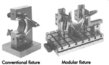
FIG. 8. Two methods of constructing a milling fixture.
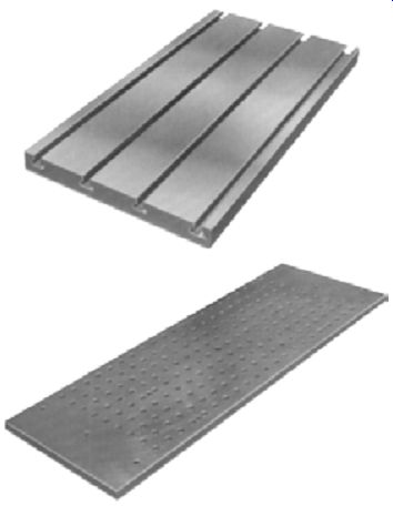
FIG. 9. Subplates.
Riser/Tooling Blocks
Most machining centers have unusable dead space between the centerline of the spindle and top of the machine table or pallet. This dead space varies between machines, but in each case it places limitations on the machine. To work around these limitations, operators will some times move the workpiece to the edge of the table to get more vertical quill movement. This arrangement, however, prevents machining the back of the workpiece without resetting the job, thereby eliminating the cost-saving potential provided by the indexable pallet.
Another method used by operators is to elevate the workpiece on blocks high enough to eliminate the dead space. This method is costly in terms of setup time. Riser/tooling blocks (FIG. 10) offer a workable alternative to the time consuming double setups and eliminate the need for unstable parallels. The riser/tooling block is mounted squarely in the center of the machining center pallet. The dead space is eliminated by the additional height of the block, thereby allowing the operator to make full use of the machine's indexing capacity to machine up to five sides of a workpiece in one setup. The riser/tooling block's heavy-duty construction, along with qualified dowel holes or T-slots, ensures that setups will be solid and repeatable.
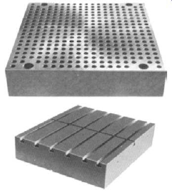
FIG. 10. Riser/tooling blocks.
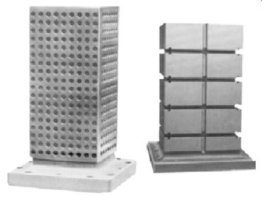
FIG. 11. Four-sided tooling blocks.
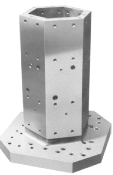
FIG. 12. Six-sided tooling blocks.
Four-sided tooling blocks (FIG. 11) are designed for use on horizontal machining centers and provide four identical surfaces for attaching workpieces or other components. When mounted on a rotary table or fourth axis, they can be indexed 90° to present four work setups to the cutting tool in rapid succession. In some cases, even the top surface is used to locate the work pieces for machining. Six-sided tooling blocks (FIG. 12) are used in the same manner as the four-sided blocks, but with the addition of two identical mounting surfaces.
Two-sided tooling blocks (FIG. 13) are set up on the machine table in the same manner as four-way blocks, but provide more Z-axis travel. When mounted on a rotary table or fourth axis, they can be indexed 180° to present two work setups to the cutting tool in rapid succession.
Two-sided tooling blocks are the logical solution to mounting workpieces too large to clear the spindle or coolant-chip shield if mounted on a column subplate. The open-frame design pro vides an access opening so the spindle can reach the back of the workpiece after indexing. Operations then can be performed on the front and back of the workpiece using the same setup.
Angle Plates
Angle plates (FIG. 14) are ideal for machining operations where a four-sided tooling block is neither required nor economically feasible. They are also suited for applications that require the fixture mounting near the front edge of the pallet, for extra thick workpieces that take up most of the pallet, and for workpieces that require their centerline to also be on the centerline of the pallet.
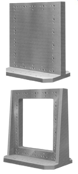
FIG. 13. Two-sided tooling blocks.
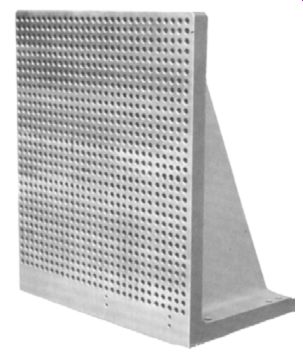
FIG. 14. Angle plate.
Tooling Cubes
Tooling cubes (FIG. 15) are designed for use on many of the newer machining centers equipped with pallet changers that have limited weight capacities. The inside of the tooling cube is hollow and necked down at both ends to reduce weight while still providing sufficient rigidity to resist intense machining forces. Tooling cubes can be located quickly against edge stops with dowel pins or parallels. They are usually bolted to the pallet through the center with threaded alloy bolts using either standard straps or a made-to-fit cover.
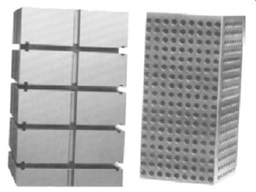
FIG. 15. Tooling cubes. (Mid-State Ma chine Products)
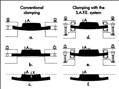
FIG. 16. Modular tooling system with self-adjusting fixturing elements.
Self-adjusting Fixturing elements
The major components of a modular tooling sys tem with self-adjusting fixturing elements include grid plates, pallets, consoles, tombstones, double angle plates, and angle plates in various sizes.
Mounting holes are multipurpose with .50 in. (12.7-mm) diameter bushings at the top and 1/2-13 threaded inserts at the bottom, or with .63-in. (16.0-mm) diameter bushings at the top and 5/8-11 threaded inserts at the bottom.
They are located on a grid pattern with either 2.0000 in. ±.0016 in. (50.800 mm ±0.041 mm) or 2.0000 in. ±.0004 in. (50.800 mm ±0.010 mm) spacing between centers. Components can be attached using dowel pins to locate and bolts to clamp them with, or by using two shoulder bolts that both locate and clamp.
With conventional clamping, castings and forgings, which are often badly warped, are usually clamped at three points using strap clamps.
The warped undersurface locates unevenly at these points, as shown in FIG. 16a. When clamping pressure is applied, severe strains are produced (b). After machining, the surface will spring out flat when the clamps are released (c), resulting in scrap or rework.
With the S.A.F.E. system, the hardened steel elements "float" in their sockets to adjust to workpiece irregularities and the surface profile, as shown in (d). The upper arms of the clamps adjust in the same manner during clamping (e), without causing distortion of the workpiece. When the workpiece is removed, the machine surface does not change.
Quick-Change Tooling
Machine tool productivity is greatly enhanced by sharp reductions in setup time, workholding, and tooling. Vast changes have been made to meet the demands of flexible manufacturing cells, automated parts-handling systems, and computer-integrated manufacturing. Quick change tooling is one way to increase productivity and decrease setup time by presetting jobs and using offline setup methods, such as the pallet/fixture changers discussed earlier in this section.
Components
Quick-change tooling consists of two parts: the clamping unit and the cutting head. The clamping unit mounts to the machine tool and acts as a receptacle for the interchangeable cutting unit (FIG. 17).
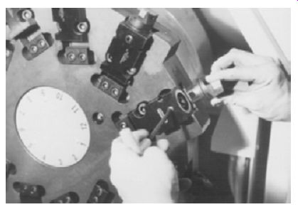
FIG. 17. Quick-change clamping unit and cutting head.
To change tooling, the machine operator simply releases the locking system, changes the cutting unit, and locks the new tool into position.
The operator then makes the offset adjustment according to the previously recorded data and continues machining the part. The total machine downtime is only about 30 seconds.
Strategies for Machining
Understanding the impact of quick-change tooling on productivity requires a review of the three basic functional areas of the manufacturing process: inventory planning and control; preproduction planning and setup reduction; and in-process machining.
Inventory Planning and Control
The primary objective of inventory planning and control is to maintain enough finished goods inventory to meet customer demand while keeping levels low enough to minimize costs.
By producing smaller lots more frequently, inventory costs can be reduced, and shelf life shortened, preventing problems such as rust, contamination, and deterioration.
Preproduction Planning and Setup Reduction
The type of planning previously discussed necessitates setup reduction. In the preproduction planning phase of the manufacturing process, all elements are identified, organized, and scheduled in advance of the production run. The objective is to eliminate as many setups as possible and improve machine and operator efficiency during setup and in-process machining.
A setup reduction program can reap as much as a 75% improvement, as well as drastically reduce tool-change time during in-process ma chining. Such a program generally consists of a number of factors.
• Quick-change tooling: an entire pre-gaged cutting unit is changed, as opposed to changing an individual insert or tool.
• Tool kitting: tooling necessary to complete a production run or shift of operation is identified, organized, and assembled.
• Pre-gaged tooling: once all tools are fitted with new cutting edges and assembled in the tool taxi, the setup dimensions are measured and recorded in advance of production.
• Preproduction tool maintenance: all tool maintenance is performed in advance of the production run to avoid catastrophic tool failure and in-process tool maintenance.
• Advanced cutting-tool materials: materials such as ceramics and polycrystalline diamonds permit longer and faster production runs.
• Tool management software: this provides computerized tracking of tools and assists in the kitting process.
Preproduction planning is the least difficult and least expensive phase of the manufacturing process. However, it can provide a significant payback by reducing machine downtime.
In-process Machining
Most of the factors that inhibit productivity can be eliminated through effective preproduction planning. While setup reduction programs most often address downtime resulting from tool change, tool maintenance, and part setup, the downtime incurred to adjust tool position for part accuracy is much less understood. This process is referred to as tool offsetting and, by traditional methods, requires an 8-minute, 17-step sequence of operations to adjust tool position and produce dimensionally accurate parts. Quick-change tooling reduces this process to a four-step procedure that takes about 30 seconds to perform.
Presetting
To achieve maximum machine productivity, presetting should encompass three functions. The first area is workholding, in which chucks, chuck jaws, fixtures, pallets, etc., must be changed each time a new lot of parts is to be run. The second area is toolholding, where part changeover necessitates the exchange of an entire toolholder, making adjustments for tool wear and repairing breakage that occurs during normal operation. This includes simple procedures, such as the indexing of an insert, in which tolerances of milled pockets and tools may not lend themselves to precision tool setting (FIG. 18).
Typically, after indexing an insert, the tool is backed off a predetermined amount, a trial cut is performed, the dimension is checked, an off set is entered into the machine (either manually or automatically), and a final is cut taken. Since cutting pressures can affect metal removal, the subsequent part cycled taking a cut at full depth will also require inspection to verify that the compensation factor was correct. In the event that the offset was incorrect, at best the process has to be repeated. At worst, the workpiece must be scrapped. Taking into account that many machines are equipped with multiple tools and spindles, and that tools frequently require dual offsets (for example, radial and depth), it is no wonder that production rates scarcely reach 40% of machine uptime.
The third area is part registry, which can be considered a natural extension of the capabilities to preset workholding devices. The concept of part registry can be defined as the accurate positioning of workpieces within a workholding device to a specified location, precisely simulating machine mounting conditions, yet prior to setting within the machine tool (see FIG. 19).
Part registry has grown in importance as the complexity and quality requirements of machined parts have increased (for example, spatial dimensions and true positioning). This has had an impact on the setup time of high-value, intricate, and fragile workpieces, where the loading, fixturing, and handling of a part are recognized as critical elements of producing a component to specification. Consideration should be given to applications involving heavy, unwieldy parts in which machine loading is time-consuming and adds operator fatigue to the equation of machine productivity. Part registry also lends impetus to the trend toward chucking a part once for multiple machine processing and transfer between machines for improved quality and productivity.
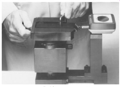
FIG. 18. Toolholder presetting.
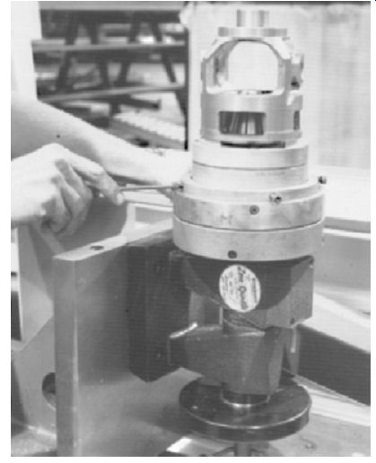
FIG. 19. Part registry.
Automatic identification
The term automatic identification is applied to barcoding and other forms of keyless data entry. The goal of automatic identification is the reliable identification of physical objects. Accuracy, speed, and reliability are reasons for implementing an automatic identification system. These systems are fast. Not only is data input quick and dependable, but the information is also provided in a virtual instant to almost any database or software package. This allows the user to make immediate and informed decisions.
Without real-time information provided by automatic identification, quality control programs can only be partially realized.
Barcoding is easy to learn and use, and relatively inexpensive to implement. By reading bar codes, data can be acquired significantly faster and more accurately and reliably than by any other means of manual input.
Barcodes
The concept behind barcode technology is identification. Any barcode symbolizes a distinctive mark of identification for products, comparable to that of a fingerprint. Barcoding can be applied to almost any aspect of the manufacturing enterprise. Quality control and tracking product life from production to customer can be stream lined and made more efficient with the use of barcoding.
The symbol itself, the information contained in it, or the language used may be referred to as the barcode. The symbol is the actual physical barcode that appears on an object being scanned.
The code refers to the information encoded in the symbol. The symbology is the language spoken by the symbol. Each barcode symbology has its own unique characteristics. For example, some symbologies can only encode numbers (numeric); others include letters and numbers (alpha-numeric). In addition to what a barcode symbology can encode, the symbology also can vary in density and character length of the printed code.
Symbology for Manufacturing
The term "symbology" denotes each particular barcode scheme. To encode data, each symbology uses a unique set of rules to determine the type of information (numeric, alpha-numeric, or ASCII characters) that can be represented. Each one-dimensional barcode is a design of wide and narrow bars and spaces called elements that rep resent the information. Over 60 different types of symbologies have been developed.
Effective Tool Management, Reporting, and Tracking
Effective tool management is critical for any industrial manufacturer. Accurate reporting of who regrinds tools, the departments or operators using various tools, and tracking tools for inventory purposes can be made faster and more effective with barcoding.
Each tool type, identification number, description, and location is entered into a data base. Identification numbers (barcodes) are assigned to each user/department of every tool or setup of items released from tool inventory.
A barcode system has the capability to track items released to departments, work centers, job orders, or even operators. A numbering system, or the modification of one, would place the tools into logical groupings. For example, a two-digit prefix may indicate the tool category, such as 02 for straight-shank drill, 04 for reamers, and so on. The use of suffixes could be used for reporting purposes.
A barcoded tool-reporting system can effectively manage the regrinding, usage, and reporting of hundreds of tools and setups. Barcodes can be attached directly to large items. Small tools, such as drill bits, can have a barcode attached to the container/bin where they are stored. A preprinted barcode menu sheet identifies what has been taken or disbursed. Operators, departments, or work centers may have an associated barcode to record normal issuance and returns.
This enables supervisors/foremen to balance tool inventory and regrinding accordingly.
Additionally, tracking information found on traditional grinding-crib time cards can be scanned off of a preprinted barcode menu sheet.
This speeds the collection of information by employees who regrind tools, allowing them to spend more time on the actual regrinding operation.
Information obtained can be reported in a timely manner with a tool-usage report. The re port helps determine what to buy and when, and what to scrap. The report also can establish a reorder point for each tool and generate a report of all tools at or beyond their reorder levels.
Timely information is an essential component to improving daily tool management. In the few cases when a tool is not in the crib, all current locations and quantities of the tool type can be quickly ascertained. The system can provide invaluable assistance in reducing hidden inventory that exists in every shop and ensure the proper inventory for daily and weekly workloads.
Radio Frequency identification (sMe 2008)
Radio frequency identification (RFID) technology is the process and physical infrastructure in which a unique identifier, and potentially other data, is transferred from a device, (also known as a tag) to a reader, via radio frequency waves.
RFID technology is used in a wide variety of applications in the supply chain as well as in manufacturing. Most RFID tags deal with the tracking of manufacturing assets. The simplest RFID system (or infrastructure) has three major components:
1. an RFID tag,
2. an RFID reader, and
3. a non-physical, predefined protocol format for the information being transferred.
The tag is a small radio transceiver that has at a minimum two components: a microchip, which holds data and the electronic circuitry providing the transceiver functionality, and an antenna used to send and potentially receive radio signals. The reader, which is usually a larger radio transceiver that has at a minimum the same two types of components as the tag, is connected to a computer network or system to which it transfers the information from the tag.
Manufacturing industries have embraced RFID technology in a variety of applications. Even though the technology is still considered relatively new, it has shown that with careful planning and a clear understanding of the capabilities along with realistic objectives, it is possible to extract real value from RFID technology.
It is important to realize that RFID technology is an enabler to process improvement, cost savings, and increased efficiencies. Thus, it needs to be considered in the complete realm of a manufacturing solution. Looking forward, the technology will embrace smaller tags holding larger amounts of information and communicating over longer ranges.
Two Primary Systems
There are two primary RFID systems: passive RFID and active RFID. In passive RFID systems, the tags contain no power source and instead rely on the magnetic field provided by the reader to power the electronics of the tag's chip. Because there is no innate power source in passive RFID systems, the range of communication is usually short-less than 32 ft (10 meters) normally.
In active RFID systems, the tag contains a power source, usually a battery. This power source is used to power the chip's circuitry. Therefore, this type of system has a much longer transmission range than that of passive RFID systems-up to 1.2 miles (2 kilometers) in open fields. This system is similar to the tracking and counting systems used on many toll roads.
Advantages
The advantage of passive RFID systems is their size. Passive RFID tags can look like a sticker of just a couple of inches (a few centimeters) in size. Because no embedded power source is required, all that is needed is the housing for the microchip (the size of a pinhead) and the antenna, which is a small coil of metal, usually copper. The primary disadvantage of passive RFID systems is their short range of transmission and their relatively high sensitivity to radio interference; the latter is due primarily to the low strength of the signal.
On the other hand, active RFID tags are usually bigger, primarily because they require an embedded power source-normally a battery.
This, however, allows for a much larger transmission range, which is the primary benefit of active RFID tags. Another benefit of active RFID tags lies in the fact that they usually can hold more memory than passive RFID tags.
Functionality
Simple RFID tags are similar in concept to bar codes in that they do not contain intrinsic information about the asset to which they are attached.
A back-end information system is necessary to provide the tag-asset association and any other information related to that asset. The difference is that barcodes in systems like the Universal Product Code (UPC) generally identify a type of asset; RFID tags, using standards like the electronic product code (EPC), uniquely identify each asset. This is common to all RFID systems.
The automation level reached by RFID systems allows for a user-friendly environment that is less prone to error. The system also relieves workers from having to know tool-specific information that could be critical for a specific task.
To achieve this level of functionality, the RFID system requires tagging the parts in inventory as well as the personnel accessing the parts' crib. The system is relatively simple. The whole physical infrastructure is made of the tagged parts and personnel tags, the antennae are embedded in the gates, and a computer collects and processes the information gathered.
Since most the RFID solutions are typically meshed within companies' networks, they be come susceptible to network issues just like any other software. Manufacturing sites that employ sophisticated electronics are always susceptible to radio interference. There are however, failsafe procedures for when things go wrong.
References
Boyes, William E. 1989. Handbook of Jig and Fixture Design, 2nd ed. Dearborn, MI: Society of Manufacturing Engineers.
Brown, Charles R. 1991. "Strategies for Innovative Machining." SME Tech Paper TE91-145. Dear born, MI: Society of Manufacturing Engineers.
DeLonghi, Charles S. 1991. "Quick Change Tooling for Today . . . and Tomorrow." SME Tech Paper TE91-144. Dearborn, MI: Society of Manufacturing Engineers.
Diehl, Werner K. 1988. "The Productive Advantages of Preset Workholding, Toolholding and Part Registration to Reduce Setup Time." SME Tech Paper TE88-125. Dearborn, MI: Society of Manufacturing Engineers.
Miller, Richard K. 1987. Automated Guided Vehicles and Automated Manufacturing. Dearborn, MI: Society of Manufacturing Engineers.
Society of Manufacturing Engineers (SME). 2008. RFID Tool Tracking Solutions DVD. Dearborn, MI: Society of Manufacturing Engineers.
SMW Systems, Inc. Here's How to Double the Output of Your Machining Center. Video. Santa Fe Springs, CA: SMW Systems, Inc.
QUIZ
1. In what manufacturing situations are modular tooling systems most valuable?
2. How do pallet/fixture changers increase productivity?
3. List four major advantages of modular tooling.
4. Name the major components of a typical modular tooling kit.
5. Name the components of quick-change tooling.
6. Name the three basic functional areas of the manufacturing process.
7. To what does the term "barcode symbology" refer?
8. List at least four items that should be part of a tool management database.
9. Differentiate and contrast between the functions for passive and active RFID systems.
10. Differentiate and contrast UPCs, RFID tags, and EPCs, and list the advantages or disadvantages for each in the comparison.