Physical and Mechanical Joining
Joining processes generally fall into two classes: physical and mechanical. In the physical joining process, parts are made to join along their contacting surfaces through the application of heat or pressure, or both. Often, a filler material is added, with the edges losing their identity in a homogeneous mass. Mechanical joining ordinarily does not involve changes in composition of the workpiece material. The edges of the pieces being joined remain distinct.
Two pieces of wood nailed together are joined mechanically. The same two pieces of wood could be joined physically by an adhesive. At the exact center of the joint, only the adhesive would be found. The adhesive would penetrate into the pores of the wood for some distance, and the work piece edges would no longer exist as true entities, but become a blend of wood and glue.
Tooling may be required to hold parts in correct relationship to one another during joining processes. Another function of tooling is to assist and control the joining process. Often, several parts may be joined mechanically and physically.
Thus, two workpieces may be bolted together to ensure alignment during subsequent welding. At times, mechanical joining may be considered as the tooling method for final physical joining.
Tooling for Physical Joining Processes
Physical joining processes generally cannot be performed without tooling because the high temperatures required make manual positioning impractical. The tooling must hold the work pieces in correct relationship during joining, and assist and control the joining process by affording adequate support. Tooling used for hot processes must not only withstand the temperatures involved, but also in many cases, either accelerate or retard the flow of heat. Hot fixtures must be designed so their heat-expanded dimensions remain functional.
Welding fixtures
The purpose of a welding fixture is to hold the parts to be welded in the proper relationship be fore, during, and after welding. Typically, distortion is a by-product of the welding process due to the amount of heat input into the parts. FIG. 1 reflects the degree of heat input associated with a given welding process.
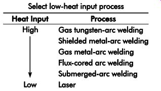
FIG. 1. Degree of heat input (Joules/inch of linear weld) based on process.
Often, a fixture will maintain the proper part relationship during welding but distort after removal from the fixture. The degree and type of distortion can be a function of the welding pro cess alone or in combination with the materials to be welded, the fixturing, or other weld-related processing such as preheating and post-weld heat treating. FIG. 2 shows typical types of distortion occurring during welding and FIG. 3 the distortion potential based on material type.
It is said that an imperfect fixture is required to make a perfect part. In other words, the fixture needs to be designed to misalign parts so distortion caused by welding brings the parts into the correct relationship to each other. Welds expand during the welding process and then contract during cooling.
A weld will shrink symmetrically if it is located on the neutral axis of the weldment section and distort transversely if it is located off of it.
Good fixture design itself will largely deter mine product reliability. Major fixture design objectives, some basic and others special, include:
• holding the part in the required position for the welding process;
• providing proper heat control of the weld zone;
• providing suitable clamping to reduce distortion;
• providing channels and outlets for welding atmosphere;
• providing access for the welding process;
• providing for ease of operation, including part loading and unloading; and
• providing a weld grounding path.
Other factors include:
• cost of fixture;
• size of the production run and rates;
• adaptability of available welding equipment;
• complexity of the weld;
• quality required in the weldment;
• welding process to be employed;
• conditions under which the welding will be performed;
• dimensional tolerances;
• material(s) to be welded;
• part-surface finish requirements (scratches, spatter, etc.);
• coefficient of expansion and thermal conductivity of both the workpiece and tool materials; and
• wear of locating surface.
The tool designer may have to be familiar with gas-, arc-, and resistance-welding processes. Each process will require individual variations to the general design factors involved. For instance, heat dissipation is not a critical factor in some of the welding processes. Expansion is not a problem if outer ends of the workpiece are not restricted.
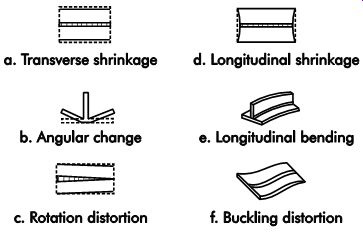
FIG. 2. Typical types of distortion occurring during welding.
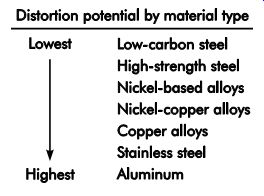
FIG. 3. Distortion potential based on material type.
Gas-welding Fixtures
The general design of a gas-welding fixture is consistent with those designed for other processes. However, the design should take into consideration the heating and cooling conditions. Minimal heat loss from the welding area is required. If heat loss is too rapid, the weld may develop cracks. Heat loss by materials, particularly aluminum and copper, must be care fully controlled. To accomplish this, large fixture masses should not be placed close to the weld line.
The contact area and clamps should be a mini mum size consistent with the load transmitted through the contact point. When welding copper and aluminum, the minimum contact surface often permits excessive heat loss, and prevents good fixture welds. This necessitates tack welding the fixtured parts at points most distant from the fixture contact points, with the rest of the welding done out of the fixture. Excessive distortion may result with this method, and the part may subsequently require stress relief by proper heating and cooling techniques.
One of the simplest fixtures for gas welding is the gravity type shown in FIG. 4. This design eliminates excess fixture material from the weld area to minimize heat loss while providing sufficient support and locating points. The design also permits making welds in a horizontal position.
FIG. 5 shows another simple form of gas welding fixture, which holds two flat sheets for joining. C-clamps hold the workpieces to steel support bars. Alignment is performed visually or with a straightedge. A heat barrier of alumina ceramic fiber is placed between the workpieces and steel bars. Hold-down plates are used to keep workpieces flat and control distortion. If the parts to be welded have curved surfaces, the supporting bars and hold-down plates may be machined to match the part.
Simple parts may be properly located or positioned in a fixture visually. Positive location is desirable as the shape of the workpiece becomes complex or the production rate increases. The same locating methods used in workholder de sign can be readily adapted for designing welding fixtures.
The selection of material for gas-welding fixtures is governed by four factors:
1. the part's print tolerances;
2. heat resistance;
3. heat-transfer qualities; and
4. the fixture rigidity required to ensure work piece alignment accuracy.
The fixture material should not be affected in the weld zone and should prevent rapid heat dissipation from the weld area. Commonly used fixture materials include cast iron, carbon steel, and stainless steel.
Arc-welding Fixtures
Arc welding concentrates more heat (energy density) at the weld line than gas welding. The fixtures for this process must provide support, alignment, and restraint on the parts, while permitting heat dissipation.
The most important consideration for arc welding is whether the parts will be manually or automatically welded. In manual welding, it is sufficient just to locate the parts in relationship to each other; the welder can find the weld joints and properly place the weld in the location. For automatic welding, assuming no use of special sensors, the weld joints themselves must be fixtured in the correct location. Automation typically locates the anticipated welds in a defined place, whether the weldment is in the correct position or not.
FIG. 4. Simple welding fixture using gravity to help locate parts.
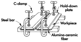
FIG. 5. Workpieces with simple fixturing for gas-welding operations.
Depending on the weld-joint configuration, either partial or full penetration welds are required. If full penetration is necessary, a backing bar is often necessary to support the weld pool.
In other words, welding takes place against the backing bar directly, or the bar serves to provide shielding to the backside of the weld and pull heat out of the weld. The molten weld pool does not actually contact the backing bar in certain situations. With a backing bar, important design considerations for arc-welding fixtures include:
• The fixture must exert enough force to pre vent or minimize parts from moving out of alignment during the welding process. Too much restraint can lead to weld cracking since the residual stresses want to relieve themselves and the solidifying weld metal provides the path of least resistance. This force must be applied at the proper location by a clamp supported with a backing bar, which should be parallel to the weld lines.
• Promote heat dissipation from the weld line.
• Support the molten weld; govern the weld contour.
• Protect the root of the weld from the atmosphere.
Backing bars are usually made from solid metal or ceramics. A simple backup could be a rectangular bar with a small groove directly under the weld. In use, the backup would be clamped against the part to make the weld root as airtight as possible. Some common shapes are shown in FIG. 6. FIG. 7 shows a backing bar in position against a fixed workpiece.
The size of the backup bar depends on the metal thickness and material to be welded. A thin weldment requires larger backup to promote heat transfer from the weld. A material with greater heat-conducting ability requires less backup than that required for a comparable thickness of a poor conductor.
FIG. 8 shows backing bars designed for use with gas, which may be used to blast (a), flood (b), or concentrate in the weld area (c). Backup bars may be made of copper, stainless steel (used for tungsten inert gas), titanium, ceramic, or a combination of several metals (sandwich construction).

FIG. 6. Typical backing bars.
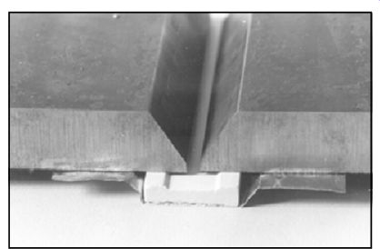
FIG. 7. Workpiece with simple fixturing for arc welding operations.
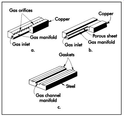
FIG. 8. Backing bars with provisions for (a) directed gas flow, (b) diffused
gas flow, and (c) pressurized gas.
Resistance Welding
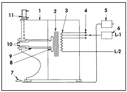
FIG. 9. Elements of a typical resistance welder: (1) housing; (2) low-voltage,
high-current transformer; (3) primary coils; (4) tap switch; (5) welding
timer; (6) power interrupter; (7) foot switch; (8) secondary loop; (9)
bands from electrodes to secondary; (10) electrodes; (11) cylinder that
exerts pressure on work.
One of the simplest and most economical processes for joining two or more metal parts is resistance welding. In resistance welding, fusion is produced by heat generated at the junction of the workpieces by local resistance to passage of large amounts of electric current and applied pressure. FIG. 9 illustrates the elements of a resistance-welding machine.
Resistance-welding processes used for low-cost, high production are shown in FIG. 10 and include spot, projection, seam, pulsation, flash butt, upset-butt, and cross-wire welding.
Other popular joining techniques include ultrasonic, high-frequency resistance, foil seam, magnetic force, percussion, friction, thermo-pres sure, diffusion bond, electro-slag, electron-beam, plasma-arc, and laser welding.
Resistance Spot Welding (RSW)
Resistance spot welding may be considerably faster and less expensive than riveting (both produce similar outcomes) as it does not require drilling holes and inserting rivets.
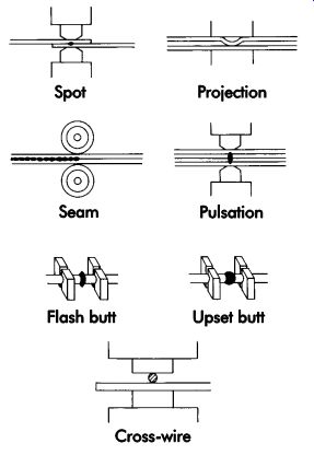
FIG. 10. Resistance-welding methods.
FIG. 11. Typical spot-welded joints.
FIG. 11 illustrates typical spot-welded joints and electrode shapes that can be produced on standard welders.
Series welding is illustrated in FIG. 12 where two welds are made with each stroke of the welder without any markings, indentations, or discoloration on one side of the assembly.
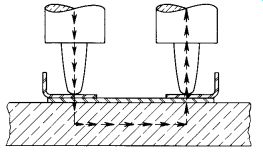
FIG. 12. Assembly showing series-welded joint.
FIG. 13 illustrates the principle of indirect welding, which is ordinarily used where the welding current must pass through the side or ends of parts due to the design. The welding-electrode tip size directly affects the size and shear strength of the weld. Tip area is a function of the workpiece material gage. For thin sheets (up to .250 in. [6.35 mm]), the diameter of the electrode tip can be calculated by:
d = 0.1 + 2t (1)
where:
d = diameter of the electrode tip, in. (mm)
t = material thickness, in. (mm)
For thick material, use (.25-2.00 in. [6.4?50.8 mm]):
d = t (2)
Projection Welding
In projection welding, embossments or projections are formed on one or both workpieces for heat localization. Dimpled workpieces are placed between plain, large-area electrodes. Projection welding provides increased strength with reduced electrode maintenance.
Seam Welding
In seam welding, the material to be welded passes between two rotating disk electrodes. As the current is turned on and off, a continuous tight seam is produced.
Pulsation Welding
In pulsation welding, the current is applied repeatedly to make a single weld while pressure is applied. This process will produce a better weld for heavier material.
Flash-Butt Welding
In flash-butt welding, the work is clamped in dies, the current is turned on, and two joints are brought together by means of cam control to establish flashing and upsetting, followed by discontinuation of the welding current. FIG. 14 illustrates a flash-welding fixture.
Upset-butt Welding
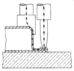
FIG. 13. Spot-welded assembly showing a typical joint design for an indirect
weld.
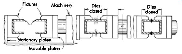
FIG. 14. Flash-butt welding.
Upset-butt welding differs from flash-butt welding in that pressure is continuous through the clamping dies after the welding current is applied. In this manner, heat is developed entirely from the resistance effect of the current.
Electrode holder and electrode function
In resistance welding, parts are positioned between electrodes that exert heavy pressure, conduct the current, and dissipate the heat from the outer surface of the materials being welded. Resistance welding is self-holding and locating, but it requires two parallel surfaces for the weld joint design. Holders and adapters are mounted in the machine so the electrode's position can be adjusted to suit a particular workpiece. Wherever possible, electrode tips should be water cooled. FIG. 15 illustrates typical standard electrode tips. The design of welding electrodes and the material from which they are made are of great importance. For in creased life, the design must provide sufficient strength with adequate heat conduction and cooling. Electrode nose shapes are illustrated in FIG. 16.
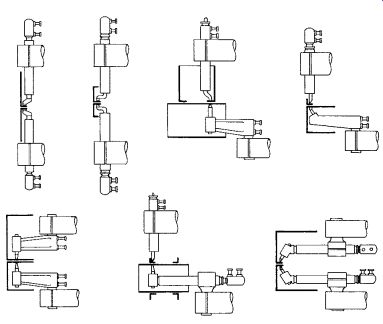
FIG. 15. Typical standard electrode tips and operations.
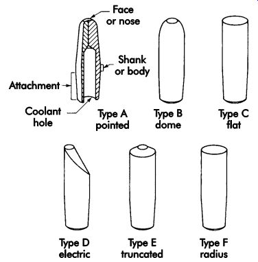
FIG. 16. Standard types of electrode face or nose shapes. (Type D was formerly
called "offset.")
Resistance Welding Fixtures
There are two general types of fixtures for resistance welding. The first is a fixture for welding in a standard machine having a single electrode.
The second is a fixture and machine designed as a single unit, usually to attain a high production rate.
Certain design considerations apply to fixtures for resistance welding.
• Keep all magnetic materials, particularly ferrous materials, out of the throat of the welding machine.
• Insulate all gage pins, clamps, locators, index pins, etc.
• Protect all moving slides, bearings, index pins, adjustable screws, and any accurate locating devices from flash.
• Give consideration to the ease of operation and protection of the operator.
• Provide sufficient water cooling to prevent overheating.
• Bear in mind that stationary parts of the fix ture and work are affected by the magnetic field of the machine.
Workholder parts and clamp handles of nonmagnetic material will not be heated, distorted, or otherwise affected by the magnetic field.
Other considerations will affect the design of resistance welding fixtures and the machine if high production is required.
• A fixture loop or throat is the gap surrounded by the upper and lower arms or knees containing electrodes and the base of the machine that houses the transformer. This gap or loop is an intense magnetic field, within which any magnetic material will be affected. In some cases, materials have actually been known to melt or puddle. Power lost by unintentional heating of fixture material will decrease the welding current and lower welding efficiency. This power loss may sometimes be used to advantage, however. For example, the addition of a magnetic material in the throat increases impedance and lowers the maximum current to prevent burning the parts during welding.
• The throat of the machine should be as small as possible for the particular job.
• Welding electrodes should be easily and quickly replaceable.
• Water for cooling should be circulated as close to the tips as possible.
• Adjustment should be provided for electrode wear.
• Current-carrying members should run as close to the electrodes as possible, have a minimum number of connections or joints, and be of adequate cross-sectional area.
• Provide adjustment for electrode wear.
• Check the welding pressure application.
• Include knockout pins or strippers if there is a tendency for the electrode to stick on its face. These may be leveraged or air operated.
General Design Considerations
Simple fixtures may locate a part visually with scribed lines as a guide. This is quite similar to locating parts for gas welding. For higher production, a quicker locating method is needed. A locating land may be incorporated in the fixture to accurately establish the edge position of the part to be welded (FIG. 17). In some cases, set blocks may be used in place of a locating land (FIG. 18).
When welding a variety of similar parts with different dimensions, set blocks have a distinct advantage over the land method of locating. With proper design, set blocks can be interchangeable to accommodate varying workpieces, and dowel pins may be used as locators (FIG. 19). Other means of locating include V-blocks, adjustable clamps, rest buttons and pads, spring plungers, and magnets.
Clamping Design Considerations
Clamps used in welding fixtures must hold parts in the proper position and prevent their movement due to alternate heating and cooling.
Further, they must hold and locate the part to maintain all degrees of freedom if a welding positioner is used. Clamping pressure should not deform the parts to be joined. As shown in FIG. 20, clamps must be supported underneath the workpiece. Due to the heat involved, distortion could remain in the part.
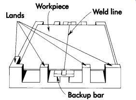
FIG. 17. Locating lands.
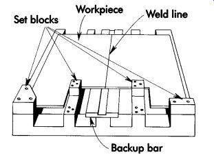
FIG. 18. Set-block locators.
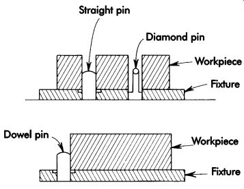
FIG. 19. Dowel-pin locators.
Quick-acting and power-operated clamps are recommended to achieve fast loading and unloading. C-clamps may be used for low production volume. Power clamping systems may be direct-acting or work through lever systems (FIG. 21). In heavier plate applications, urethane tip or spring-loaded clamp spindles are recommended to compensate for plate thickness variations.
Laser Welding
Because of the laser's high heat intensity, it can be used for a variety of processes, such as cutting, drilling, metal forming, heat-treating, cladding, brazing, and welding. There are many types of lasers, but the two mainly used in industry are CO2 and neodymium: yttrium aluminum garnet (Nd:YAG) lasers. These lasers are capable of producing electrical power of up to 6 kW (21,600 kJ) for the Nd:YAG and up to 50 kW (180,000 kJ) for the CO2 for use in generating heat.
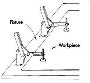
FIG. 20. Typical clamp installation with the fixture supporting the workpiece
directly beneath the clamps.
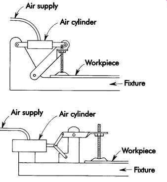
FIG. 21. Air-actuated clamping methods.
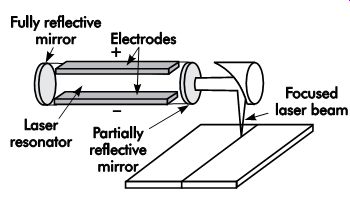
FIG. 22. Laser beam welding.
Lasers deliver energy in the form of light. This light is in the visible spectrum for many laser systems, but the CO2 and Nd:YAG lasers produce light in the invisible, infrared region. Because of the large amounts of power needed to operate industrial lasers and the damaging characteristics of the emitted light to the eye and skin, great care must be taken when performing maintenance on a laser or working in the vicinity of the emitted laser beam.
When welding, power can be delivered in pulses or in a continuous wave operation. No contact is needed with the workpiece to create a welded assembly (FIG. 22). The raw laser beam can be focused on a workpiece through a lens or parabolic mirror. Focusing the beam produces intense heat, which causes localized melting of the metal and thus the potential for high processing rates. Laser welding is capable of penetrating depths up to approximately .50-in (12.7 mm) in many steels and can be used simultaneously with other processes, such as gas metal-arc welding (GMAW) (also known as metal inert-gas-shielded arc welding [MIG]), to create greater depths of penetration. Such hybrid processes enable tailoring the weld by adding filler material to match the desired mechanical properties of the mating materials. A much tighter fixture and part tolerance is required for weld joint gap and vertical mismatch because of the small focused laser beam diameter.
Fixtures
The laser should be mounted in a firm structure to prevent vibration. The design should al low sufficient room between the worktable and focusing optic to accommodate various types of positioning devices.
The tooling used to position parts for laser welding is similar to other types of welding. However, because of the lower overall heat input into the material with laser processing, lower thermally induced stresses (low distortion) is present and less massive, so less restricting fixtures can be used. In addition, laser tooling can be scaled down to accommodate smaller parts. In numerical control operations where more than one fixture is used, working heights of fixtures must be controlled in relation to each other to prevent accidental defocusing of the laser beam.
Accidental defocusing may cause less penetration in the weld than desired. Because laser energy is delivered to the workpiece without mechanical force, no fixturing is required on small parts. Use of mechanical force for these applications could induce unwanted strains and deformations.
Soldering and Brazing
Soldering and brazing differ from welding in several respects. The filler metal is nonferrous, usually lead, tin, copper, silver, or their alloys.
The workpiece or base metal is not heated to the melting point during the operation. The added filler metal is melted and usually enters the joint by capillary action. Brazing and soldering are fundamentally the same processes. An arbitrary distinction is made between them based on the melting temperature of the filler metal. Soldering filler metals melt below 842° F (450° C) and brazing filler metals above 842° F (450° C) and below the melting point of the base substrate material.
The success of brazing and soldering depends on part cleanliness, temperature control, and the clearance between the surfaces to be joined. Cleanliness usually is obtained by introducing a flux that cleans, dissolves, and floats off any dirt or oxides. The flux also covers and protects the area by shielding it from oxidation during the process. It may, to some extent, reduce the surface tension of molten metal to promote free flow. The worst contamination usually is due to oxidation during the process. This is more prevalent with brazing because of the higher process temperatures. Some brazing and soldering operations are conducted in a controlled atmosphere or vacuum.
Temperature control, although influenced somewhat by fixture design, is dependent primarily on the heat application method. In a simple low-production process, the worker may hold a torch closer to the workpiece for a longer period of time. In a precise high-production process, the instrumentation of a controlled atmosphere-type furnace may be adjusted.
Clearance between the surfaces being joined helps determine the amount of capillary attraction, the thickness of the alloy film, and consequently the strength of the finished joint. Typical joint clearance is .002-.015 in. (0.05-0.38 mm) at the brazing temperature. The optimal joint clearance is dependent upon the particular filler metal alloy, base metal being joined, and joint configuration. Too large a clearance would lack sufficient capillary attraction, while too small a clearance may inhibit proper flow of some filler metals.
Tooling
Many soldering and brazing operations are conducted without special tooling. As with mechanical joining methods, many workholding devices can be used to conveniently present the faces or areas to be joined. An electrical connecting plug can be easily held in a vise while a number of wires are soldered to its terminals. In many high-production assembly operations, parts are manually mated with a preformed brazing ring or foil between them. Then they are placed directly on the continuous belt of a tunnel-type furnace or gas-heater-ring fixture.
If the shape of the workpiece will not support itself in an upright or convenient position, a simple nesting fixture may be required. FIG. 23 shows a simple nesting fixture in which two workpieces and a brazing ring have been placed. The fixture can be mounted on a table while an operator applies heat with a hand torch. The same fixture could be mounted on a powered rotating base in the flame path of a fixed torch while a feed mechanism introduces wire solder at a predetermined rate (FIG. 24). Or, the same fixture could be attached in quantity to the belt of a tunnel furnace or to a rack for processing in a batch furnace.
Some brazing and soldering processes dictate more tooling than others. For instance, hand soldering often requires no special tooling at all, while induction brazing may require significant tooling/fixture design and development. Nevertheless, several aspects are common to almost all brazing and soldering tooling and/or fixtures.
• The tooling material must be stable at the intended process temperatures. Tooling and fixtures often are heated along with the parts being joined. Consequently, they must be made from materials with melting temperatures that are high enough, possess adequate hot strength, and not react with base metals or the process atmosphere unfavorably. For high-quantity production processes, corrosion of tooling and fixtures can be a particularly serious concern.
• The process must account for the differences in the coefficients of thermal expansion (CTE) of tooling and fixtures relative to that of the parts being joined. This is particularly true for fixturing that maintains critical tolerances. A significant CTE mismatch between the fixture and the workpiece may lead to excessive distortion of either one or both.
• Fixtures must allow adequate and uniform heating of the entire joint surface. If a fix ture acts as a chill for one part of the joint, this may result in incomplete bonding and a defective joint. However, even the best fixture design always must be accompanied by proper procedure development to prevent this type of problem.
• The mass of any tooling or fixtures that will be heated during the process, even in part, should be minimized as best as possible to limit the amount of heat required. This is particularly true for high-quantity production processes where the cost just for heating the tooling could be substantial. Low thermal-conductive materials, such as ceramics, often are used to minimize heat loss to and/or through a fixture component.
• Precautions must be taken to prevent the tooling or fixtures from being inadvertently bonded to the workpiece. Proper design and/ or using materials, such as ceramic, stainless steels, and titanium, which are not as easily wet by conventional brazing and soldering alloys, provide added insurance. It should be noted that, in some cases, the filler metal may wet and flow well beyond the intended joint area.
As is the case with most joining processes, good tooling and fixtures cannot compensate for poor procedure development or selection of the wrong brazing or soldering process. For example, a fixture may appear to be acting as a chill on part of an assembly, causing incomplete wetting in a torch brazing application. However, this may actually be the result of an inadequate heating rate due to poor torch placement, gas flow rates set too low, improper flame adjustment, or improper fuel-gas selection.
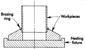
FIG. 23. Simple nesting fixture with work in place.
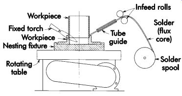
FIG. 24. Soldering machine using simple nesting fixture.
Induction Brazing
FIG. 25 illustrates a nest-type fixture to hold mating workpieces within the field of an induction work coil. FIG. 26 shows the same fixture altered to permit use of an internal induction-heating coil. If the external coil is used, the fixture designer must provide some method of moving the fixture or coil while workpieces are loaded and unloaded.
Induction coils (inductors) provide a convenient and precise way of quickly and efficiently heating any selected area of an electrically conductive part or assembly to a required depth to provide a brazed joint. Correct selection must be made regarding frequency, power density, heating time, and inductor design.
Induction Heating Theory
The flow through an electrical conductor results in heating as the current meets resistance to flow. Thus, I^2 R losses (I = current; R = resistance) may be as low as current flowing through copper wire (resistance is low) or high when this same current reaches and flows through a heating element (resistance is high). This high loss is characteristic of the resistance heating obtained with conventional electric heaters.
Induction heating is resistance heating with current flow meeting resistance. A workpiece heated in this manner has been made the secondary of a simple transformer, the primary being the inductor that generally surrounds the part and through which alternating current is flowing. The flow of alternating current in a primary induces a flow of current in the secondary by electromagnetic forces (magnetic flux). Alternating current tends to flow on the surface, and there is a relationship between the frequency of the alternating current, the depth to which it flows, and the diameter of stock that can be heated efficiently.
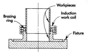
FIG. 25. Nesting fixture for brazing with an external inductor.
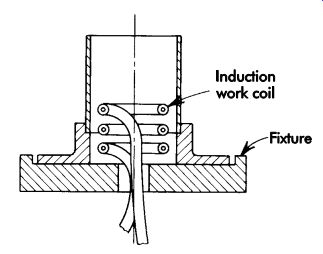
FIG. 26. Nesting fixture for brazing with an internal inductor.
Consider a piece of plain carbon steel being heated for brazing or surface hardening. The depth at room temperature, in which there is instantaneous flow of current, is related only to the frequency:
D = 4/F (3) where:
D = depth, in. (mm) F = frequency in cycles/sec
The depth, D, increases with temperature. For heat to be generated, the I^2 R must have a time factor, t, to become:
I^2 Rt (4)
Additional depth results from the current following the path of least resistance (cooler underlying metal) and heat flow by conduction.
This depth may be approximated by:
D = 0.0015t (5)
where:
D = depth of heat penetration, in. (mm) t = time, sec
The higher the frequency for a given heating time, the shallower is the depth of heat penetration. The converse is true. For a given frequency, the depth of heat penetration is also directly proportional to the time.
An examination of Equation 3 will provide an answer to the relationship between frequency and the diameter of stock that can be heated efficiently.
Large diameters may be heated efficiently with low frequency. Sixty cycles are used efficiently on 10-in. (254-mm) diameter steel workpieces.
The theoretical depth of current penetration mentioned previously increases with temperature and must never exceed the radius of the stock being heated. For practical purposes, this depth, D, (D = 4/F at room temperature) should be two to three times the radius for through-heating, and 10 times the radius for surface hardening.
Inductor Design
An inductor should have the following characteristics:
• proper physical shape to surround the section to be heated;
• large enough diameter to permit loading and unloading or, in the case of a continuous operation, clear passage;
• proper support or rigidity to maintain its designed shape;
• insulation to avoid electrical breakdown (spacing or an air gap between turns and the workpiece usually is sufficient); and
• ability to withstand operating conditions (exposure to water, dirt, and flux must be taken into consideration).
Power density and heating time are closely related to the design of the inductor. The inductor design is integral to the success of any induction-heating application. The purpose of the inductor is to set up a magnetic flux pattern in which the work to be heated is correctly positioned so the required heating is accomplished (FIG. 27). Coil design is influenced by the application, as is the selection of frequency, power density, and heating time.
A solid-type inductor is preferred because of its greater rigidity. Accidental contact while loading parts will not bend it out of shape. Less expensive coils can be made of copper tubing which, except for extremely low power (1 kW [3,600 kJ] per coil), should not be less than .19 in. (4.8 mm) in diameter.
Both round and rectangular sections are used; the rectangular section is especially adaptable when a wide, single turn is needed. Its wide flat area can be adjacent to the work for more uniform heating. A 1.00-in. (25.4-mm) wide inductor can be made of .25 x 1.00 in. (6.4 x 25.4 mm) tubing or from a wide, flat strip brazed to a round tube for cooling.
Regardless of the material used in the induction-brazing process, the inductor must be de signed to heat the area of the joint sufficiently to cause the bonding material to flow. Temperatures can range from a few hundred degrees for soft solder and epoxies to 2,100° F (1,149° C) for cop per. When attempting to heat heavy sections and avoid overheating of sharp corners on small- or medium-size workpieces, the use of motor generators at 3,000 or 10,000 cycles is preferred.
Inductors must have sufficient cooling to avoid overheating. Copper normally is used for coils with appropriate water cooling. This can be accomplished by using copper tubing, solid cop per to which tubing has been attached, or solid copper that has been drilled out or machined to provide water passages. Cooling water may be brought in from the output transformer through connectors carrying the current, or from separate insulated connections to a water supply. For a brazing operation, an inductor can be made by forming copper tube on a suitable mandrel. The tube must not collapse to restrict internal coolant flow.
The air gap or space between the work and the inside of the inductor should be kept low for efficiency. A gap of .125 in. (3.18 mm) is reasonable. For irregularly shaped sections where efficiency is not too important, gaps of .25 in. (6.4 mm) and greater can be tolerated.
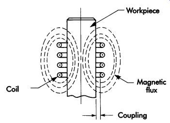
FIG. 27. Magnetic flux in induction heating.
The area to be heated determines the length or width of the inductor. For most joint designs on small parts, a single turn is sufficient. On larger diameters, it is necessary to heat a wider band requiring either several turns or a wider inductor.
An inductor that is too narrow will simply require a longer heating time to allow the heat flow to cover the area. One that is too wide will heat more metal than necessary and be less efficient. A single-turn inductor should be no wider than the bore diameter; for greater coverage, multi turn inductors are used.
The electrical characteristics of a high-frequency power source determine the number of turns in an inductor. Generally, the high frequencies of a vacuum tube oscillator (200-3,000 kHz) usually require multi-turn coils, whereas the motor-generator sets (1-10 kHz) can operate into either multi-turn or single-turn coils through the use of variable-ratio transformers. Turns of the inductor should be kept as close as possible without touching. Typical inductors are illustrated in FIG. 28.
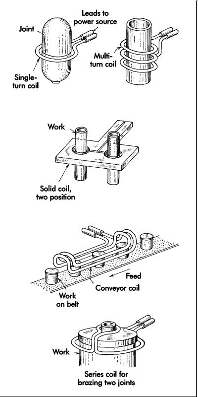
FIG. 28. Designs of induction-heating coils for brazing.
When tubular sections are to be joined, it is of ten more convenient to heat from the inside. The factors of coil design essentially are the same as for inside diameter (ID) inductors, except that the leads must be brought to the coil axially instead of radially (FIG. 26). Since heating from the ID is considerably less efficient (the magnetic flux is weak outside the confines of the coil), two to three times as much energy (kilowatt seconds [joules]) may be required. This can be obtained by using more power, or time, or both. When high production requirements preclude the use of a longer heating cycle, the ID coil efficiency can be improved by using an inside core that increases the magnetic flux outside of the coil. Basic design elements are as follows:
• For vacuum-tube oscillators, compacted ferro magnetic stock may be used. This material, which can be purchased in round bars, is then made a core inside the inductor. The turns can be held tightly on the surface or wound in grooves machined in the core. No insulation is required, and one lead may be brought through a hole in the center of the core.
• For motor generators, iron laminations are used. They are made from .007-in. (0.18 mm) thick strips of transformer steel, .25-in. (6.4-mm) wide, which has been cut to the correct coil length. The strips are wound together and inserted in a multi-turn coil to form a core. If a single-turn inductor is used, laminations are cut in a C-shape and stacked tightly around the turn, as shown in FIG. 29.
The design of inductor coils for brazing operations is relatively simple. There should be no problem with electrical matching to the proper power source. The physical configuration is dictated by the shape and size of the area to be heated. The inductor is a primary winding for a transformer with the workpiece acting as a secondary. The coil need only be formed to surround or-for ID heating-be adjacent to the surface to be heated.
A wide latitude of shape is permitted. A square part can be heated with an inductor formed on a square (FIG. 30) or round mandrel. Ir regularly shaped parts can be heated with round inductors. If a corner of a workpiece overheats, the inductor can be modified to merely provide a larger air gap at the corner.
Occasionally, a joint must be heated by proximity. An ID coil cannot be used as it would necessitate heating entirely too much metal. An inductor for heating such an area is shown in FIG. 31. Such an inductor is insufficient and can be improved by use of laminations as shown. The C-shape is open toward the work.
Generally, an inductor should have the same contour as the area to be heated. With a reason ably uniform coupling, the part can be loaded with no difficulty. When there are large changes in diameter in the section to be heated, the larger diameter will tend to overheat unless some compensation is made. This can be done by having fewer turns per linear inch (millimeter) in that area, by increasing the coupling, or using two turns in series (electrically) on the small diameter (FIG. 32). The intensity of the magnetic field in which the surface finds itself should be as uniform as possible.
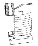
FIG. 29. Special-purpose inductor.
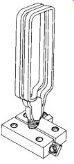
FIG. 30. Inductor formed on a rectangular mandrel.
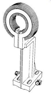
FIG. 31. Inductor with C-shaped laminations added.
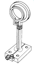
FIG. 32. Inductor with loops in series.
Process Parameters
The number of inductors used at one time is, of course, influenced by production requirements.
The number can be extended to as many as may be convenient to load. Instead of a large number, a continuous coil can be used, through which parts are moved progressively. Generally, this method is limited to a workpiece having a joint on or near its end. The determination of how many parts are to be processed at a time is related to heating time and power density. The time generally runs from 10 or 15 seconds on small parts to as long as two minutes on large parts where heat must penetrate. The power density is approximately .5-1.5 kW/in.^2 (279-837 kJ/cm^2 ) of surface area. An average value of 1 kW/in.^2(558 kJ/cm^2 ) is recommended. The actual value depends on the ratio of surface area to volume.
The amount of energy (kilowatt seconds) is determined by the volume of metal to be heated and the temperature necessary to flow the bonding material. Since the exact amount of metal heated in a brazing operation depends on many factors, such as conductivity of the work and heating time, only a rough approximation can be attempted. The following procedure is recommended (using U.S. Customary units):
1. Estimate the volume of metal expected to be brought to brazing temperature.
2. Convert the volume to weight in pounds based on steel weighing .3000 lb/in.^3
3. For 400° F solder, convert to kilowatt seconds by multiplying by 100.
4. For 1,200° F brazing material, convert to kilowatt seconds by multiplying by 300.
5. For 1,600° F brazing material, convert to kilowatt seconds by multiplying by 500.
6. For 2,000° F brazing material, convert to kilowatt seconds by multiplying by 700.
7. Estimate the surface area of the joint. Based on 1 kW/in.^2 , divide the area into the preceding value of kilowatt seconds to determine the approximate brazing time in seconds.
8. Determine from the production requirements (allow for handling each part) the number of parts to be processed at a time.
9. The total power required will depend on the above value and kilowatts per piece based on 1 kW/in.^2 of surface area.
10. The power available is determined by the equipment to be used. The maximum number of parts that can be processed at once can be approximated by dividing the kilowatt rating of the equipment by the surface area of each part in square inches (kW/in.^2 ).
Leads
The leads to the inductor should be kept as short as possible and close together. In some situations, coaxial leads may be necessary (450 kHz and up). If the leads are not a continuation or part of the inductor and a brazed joint is used, they must not reduce current flow to the inductor. Silver solder is recommended, and carefully prepared joints (even mitered) are essential. Insulating materials should be used between leads if they are not self-supporting. The connection to the power source will be determined by the design of the output transformer.
Coil Support
Solid inductors usually are self-supporting, as are single-turn inductors. Support of multi turn inductors or an array of inductors can be accomplished with any nonmetallic material.
Many plastic materials can be used. Coils can be attached by studs (preferably copper) brazed to the inductor. Use of copper or bronze-brass studs is highly recommended, as cooling water will cause rust problems with steel or any ferrous metal and hinder stud removal.
Tooling for Thermal Cutting
Three basic types of thermal-cutting systems are used in metal-fabricating operations: oxy flame, plasma-arc, and laser.
Laser cutting is primarily used on different types of numerically controlled (NC) and computer-numerically controlled (CNC) machines.
Machines equipped with lasers generally have a large working table area (60.00 × 50.00 in. [152.4 × 127.0 cm] nominal sheet size). The workpiece is held in position by several hydraulic holders or clamps. Many of the machines have nesting capabilities, which allow more than one part per material sheet.
Plasma-arc cutting can be used to cut irregular shapes. It also is used on thermal machining centers. These machining centers carry one or more torches on a traveling bridge. Typically, these are computer controlled. Prior technology utilized optical scanners that followed a paper template or digital tape control method. The material to be cut is placed on water tables. The water table is used to control smoke, noise, and ultraviolet radiation. A dye in the water eliminates ultra violet emissions.
Oxy-flame or oxyacetylene cutting machines employ the same method as plasma-arc machining centers, except that the cutting tables do not normally contain water. The cutting table contains a number of cross-supports on which the workpiece is set. These cross-supports are held in position by a square or rectangular container into which the drop-outs fall. After several cutting operations, the cross-supports must be replaced because they become damaged during the cutting operation.
Some fixturing is used on plasma-arc and oxy-flame machining centers. These fixtures are constructed to support the material to be cut, allowing for proper heat dissipation to prevent distortion. The fixtures use standard components. The key to designing fixtures for cutting operations is allowing clearance for cutting media below the piece-part. If there is insufficient clearance, fixture damage may result.
Added precautions must be taken when cutting high-alloy steels. This is due to the hardening ability of the workpiece at the line of cutting, and suitable machining allowance or post-heat treatment must be considered.
Tooling for Mechanical Joining Processes
Many workpieces can be held for mechanical joining without tooling. A worker often can manually align two workpieces and insert a fastener. This method has several limitations, however. The workpiece must be small or light enough to be positioned manually, and the forces incurred in the joining process must be relatively small. The complexity of an assembly joined in this manner is limited by the number of components a worker can conveniently handle. Thus an elementary workholder often can be used to advantage in even the most simple joining operation.
A universal-type vise can be of great value in mechanical joining. A primary workpiece can be held in any position while other workpieces are fastened to it. Several workpieces may be held in alignment between the jaws while the worker applies a fastener. Clamping pressure can be used to counteract the joining forces, such as torque applied to a threaded fastener.
Threaded fasteners
Threaded fasteners are used for a wide variety of applications, and the bolt and nut are the most common. Tooling for threaded fasteners is as varied as the applications. There are, however, design principles that apply to all cases.
A primary use of threaded fasteners is for joining and holding parts together in load-carrying applications, especially when disassembly and reassembly may be required. Typical assemblies for several types of threaded fasteners are illustrated in FIG. 33. Threaded fasteners are also used extensively for assemblies subjected to harsh environmental conditions, such as high temperatures and corrosion.
Advantages of threaded fasteners include their commercial availability in a wide range of standard and special types, sizes, materials, and strengths, as well as the ability of the assembly to be disassembled easily. Extensive standardization efforts have made most threaded fasteners interchangeable.
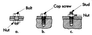
FIG. 33. Typical assemblies using threaded fasteners: (a) bolt and nut;
(b) cap screw; (c) stud.
Bolts and Studs
Bolts are externally threaded fasteners generally assembled with nuts (FIG. 33a). While most bolts have heads, some do not. The means of distinguishing between bolts and screws are discussed in ANSI B18.2.1 ("Square and Hexagonal Bolts and Screws, Inch Series"). Studs are cylindrical rods threaded on one or both ends or throughout their lengths (FIG. 33c).
Bolts with hexagonal heads, frequently called hex heads, are the most commonly used. These heads have a flat or indented top surface, six flat sides, and a flat bearing surface. The flat sides facilitate tightening the bolts with wrenches.
Hex heads often are used on high-strength bolts, making them easier to tighten than bolts with square heads. Generally, hex heads are available in standard and special strength grades to meet the requirements for specific applications.
Round-head bolts have thin circular heads with rounded or flat top surfaces and flat bearing surfaces. When provided with an underhead configuration that locks into the joint material, round-head bolts resist rotation and are tightened by turning their mating nuts. Included in this classification, even though the configurations differ, are countersunk and T-head bolts.
Variations of round-head bolts include those with square, ribbed, or finned necks on the shanks below the heads to prevent the fasteners from rotating in their holes.
Square-head bolts have square-shaped, external wrenching heads. They are available in two strength grades. Lag bolts, sometimes called lag screws, usually have square or hex heads, gimlet or cone points, and thin, sharp, coarse-pitch threads. They produce mating threads in wood or other resilient materials and are used in masonry with expanding anchors.
Battery bolts have square heads and are mostly stainless steel or lead- or tin-coated for clamping onto battery terminals. Fitting-up bolts have square heads and coarse-pitch, 60° stub threads. They are used for the preliminary assembly of structural steel components. T-bolts are square-headed bolts used in the T-slots of machine tools.
Bent bolts are cylindrical rods having one end threaded and the other bent to various configurations. These include eyebolts, hook bolts, and J-bolts. Other bent bolts, such as U-bolts, have both ends threaded. The ends of bent bolts are usually square (as sheared).
Studs are unheaded, externally threaded fasteners. They are available with threads on one or both ends, or continuously threaded. Studs with collars and threaded on one or both ends also are available.
Heat-treated and/or plated studs are available to suit specific requirements. They are made with chamfered or dog-point ends.
An advantage of studs for some applications, such as the assembly of large and heavy components, is their usefulness as pilots to facilitate mating of components, which expedites automatic assembly. For many applications, studs provide fixed external threads, and nuts are the only components that must be assembled.
Nuts
Nuts are internally threaded fasteners that fit on bolts, studs, screws, or other externally threaded fasteners for mechanically joining parts. They also serve for adjusting and transmitting motion or power in some applications, but they generally require special thread forms.
Hex and square nuts, sometimes referred to as full nuts, are the most common. Hex nuts are used for most general-purpose applications. Square ma chine-screw nuts usually are limited to light duty and special assemblies. Regular and heavy square nuts often are used for bolted flange connections.
Single-thread nuts, sometimes called spring nuts, are formed by stamping a thread-en gaging impression (arched prongs) in a flat piece of metal (FIG. 34). These nuts are generally made from high-carbon spring steel (SAE 1050-1064), but are also available in corrosion-resistant steel, beryllium copper, and other metals.
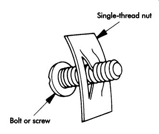
FIG. 34. Single-thread nut.
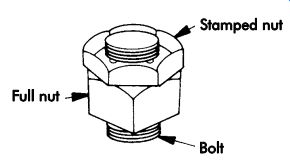
FIG. 35. Stamped nut applied and tightened after full nut is in place.
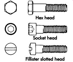
FIG. 36. Cap screws with various heads.
Stamped nuts are hex fasteners stamped from spring steel or other metals, with prongs formed to engage mating threads. Like single-thread nuts, they rely on spring action for clamping and resistance to loosening, but they have more prongs to engage the threads on the mating fastener.
Applications include replacement for full nuts in low-stress uses and as retaining nuts against full nuts (FIG. 35). Stamped nuts are made with integral washers, in closed top or bottom styles, and as wingnuts.
Screws
Screws are externally threaded fasteners capable of insertion into holes in assembled parts, mating with preformed internal threads, or cutting or forming their own threads. Because of their basic design, it is possible to use some screws, which are sometimes called bolts, in combination with nuts.
Screws are available in a wide variety of types and sizes to suit specific requirements for different applications. Major types discussed in this section include machine screws, cap screws, setscrews, sems (screw and washer assemblies), tapping screws, and captive screws.
Machine screws. Machine screws usually are inserted into tapped holes, but are sometimes used with nuts. They are generally supplied with plain (as sheared) points, but for some special applications they are made with various types of points.
Machine screws have slotted, recessed, or wrenching heads in a variety of styles and are usually made from steel, stainless steel, brass, or aluminum.
Many machine screws are made from unhardened materials, but hardened screws are available too.
Cap screws. Cap screws are manufactured to close dimensional tolerances and designed for applications requiring high tensile strengths.
The shanks of cap screws are not fully threaded to their heads. They are made with hex, socked, or fillister slotted heads (see FIG. 36). Low-head cap screws are available for applications having head clearance problems. Most cap screws are made from steel, stainless steel, brass, bronze, or aluminum alloy.
Setscrews. Setscrews are hardened fasteners generally used to hold pulleys, gears, and other components on shafts. Hardness of the shaft is an important consideration in selecting a proper setscrew. They are available in various styles, with square-head, headless-slotted, hex-socket, and splined- (fluted) socket styles being the most common. Holding power is provided by compressive forces, with some setscrews providing additional resistance to rotation by penetrating their points into the shaft material.
Sems. Sems (screw and washer assemblies) is a generic term for preassembled screw and washer fasteners. The washer is placed on the screw blank prior to roll threading and becomes a permanent part of the assembly after roll threading, but is free to rotate. Sems are avail able in various combinations of head styles and washer types. Washers commonly used include flat (plain), conical, spring, and toothed lock.
Suitable for automatic-assembly operations, sems are used extensively in the manufacture of automobiles and appliances and in other mass production industries. These fasteners permit convenient and rapid assembly by eliminating the need for a separate washer-assembly operation. They also ensure the presence of the proper washer in each assembly and prevent the loss of washers during maintenance.
Tapping screws. Tapping screws will cut or form mating threads when driven into holes.
Self-drilling, self-piercing, and special tapping screws are also available. They are made with slotted, recessed, or wrenching heads in various head styles and with spaced (course) inch or metric threads. Tapping screws are mostly used in thin materials.
Advantages of tapping screws include rapid installation because nuts are not needed and access is required from only one side. Mating threads fit the screw threads closely, with no clearances necessary. Underhead serrations or nibs on some screws increase locking action and minimize thread stripout.
Captive screws. Captive screws remain attached to panels or assembly components after they have been disengaged from their mating parts. Advantages include fast assembly and disassembly, and prevention of damage to other assembly components caused by lost or loose screws.
Threaded assembly
The most common method of threaded assembly is to place two workpieces in their correct relative location, drill a hole through them, insert a bolt in the hole, and torque a nut onto the bolt.
The hole may have been drilled in both pieces prior to mating. In many cases, no tooling will be required. If it is convenient for a worker to hold the workpiece together while inserting the bolt and adding and tightening the nut, then a simple workholder may be advantageous. The work holder must locate the workpiece so the holes are conveniently positioned, and it should support the workpiece against the torque and thrust loads imposed in tightening the fasteners.
One of the two workpieces being assembled may be tapped to receive the threaded fastener, or a self-tapping fastener may be used. Power tools may be used to drive the fasteners. The fixture design principles for nut runners are: (a) location-the fixture must align the workpiece precisely with the nut runner; and (b) support-the fixture must withstand the weight of the workpiece plus the thrust and torque loads imposed.
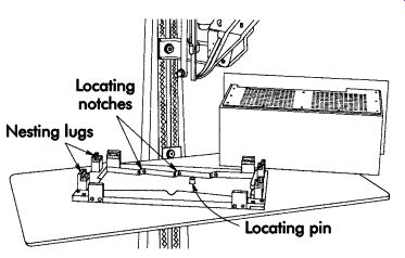
FIG. 37. Partial nest-type workholding fixture for assembly of a cabinet.
FIG. 37 shows a template nesting fix ture resting on the table of a power screwdriver. It is designed to hold a metal cabinet while two side shields are assembled to it by 20 self-tap ping screws. A round locating pin is attached to the machine table exactly under the driver.
The fixture base is a template and has 10 radi used notches that can be manually held against the locating pin. When the components of the cabinet are placed in the fixture, each template notch is directly beneath a predrilled hole in the components, into which a screw is to be inserted. As each notch is held against the locating pin, the predrilled hole is placed directly beneath the driver and the machine is cycled to insert and drive one screw. After 10 screws have been driven to secure one side shield, the cabinet is inverted and another 10 screws are driven to fasten the other shield.
The fixture design principles are the same as described previously. It must precisely locate the workpiece relative to the driver. In this case, 10 precise location points are involved. The fixture also must establish the exact height of the work piece and support it in resistance to the torque and thrust loads imposed.
For high production volumes, several machines may be arranged to simultaneously insert and drive screws into a single fixtured workpiece.
Rivets
Perhaps the most widely used pin-type fastener is the rivet-a pin with a head on one end with the other being plastically deformed after insertion to prevent retraction. The riveting process is extremely varied-it may be used to assemble the parts of a timepiece or the structural members of a bridge. Rivet diameters vary from .015-5.000 in. (0.38-127.00 mm). Holes may be drilled or pierced before or during the operation.
It is important that a riveting tool of the correct size and shape be used, and that excessive driving pressure is avoided. Excessive pressure in driving may result in:
• bulging of the edge of the piece being riveted;
• buckling or other distortion, particularly if thin material is used; and/or
• weakening or fracturing of metal near the hole.
FIG. 38 shows an L-shaped workpiece clamped in a fixture while a second workpiece, a channel, is being riveted to it. The portable riveting yoke literally squeezes the rivets to deform them. Holes are drilled and rivets are inserted prior to the operation. In practice, it would be necessary to employ stops or other means to locate the channel with Reference to the primary workpiece.
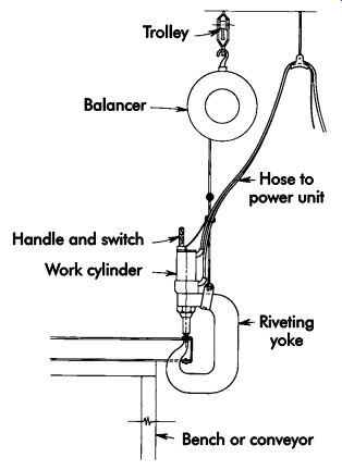
FIG. 38. Workpiece simply supported for riveting.
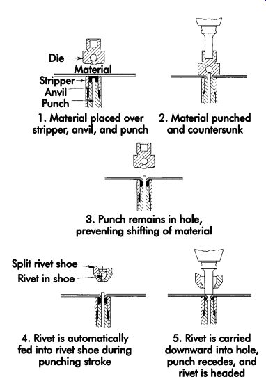
FIG. 39. Sequence of punching and riveting operations.
FIG. 39 shows the sequence of a punching and riveting operation used in mass production. The two workpieces are placed between the tools, and the machine is cycled to automatically pierce a hole, insert a rivet, and then head the rivet.
Eyeleting
Eyelets, like rivets, are used extensively as low-cost fasteners for light assembly work. For high-production operations, costs can be reduced to a minimum with the use of eyelet-attaching machines. These machines are small power presses with hopper-feed mechanisms. FIG. 40 illustrates typical tooling of an automatic eyelet-setting machine in loading and clinching positions.
Tubular riveting
A tubular rivet is a cross between a solid rivet and an eyelet. The straight end of the rivet has a center hole that permits this part of the rivet to clinch easily when struck by the contoured riveting tool. FIG. 41 illustrates tooling for a typical tubular riveting operation.
Clinch allowance
Clinch allowance is the space caused by the part of a rivet or eyelet that extends beyond the combined thickness of the assembly before the rivet or eyelet has been set. FIG. 42 shows the rivet or eyelet length in relation to material thickness and clinch allowance. The proper rivet or eyelet length should be approximately equal to the material thickness plus the clinch allowance. Both rivets and eyelets are available commercially in .03-in. (0.8-mm) length increments. Two rules of thumb have been developed: (1) the maximum length of the clinch for full-tubular and bifurcated rivets should be figured at 100% of shank diameter; and (2) the maximum length of the clinch for semi-tubular rivets should be 50-70% of the shank diameter to prevent buckling and ensure a tight set.
The hole diameter and method of producing the hole in the material also affect the clinch diameter. The minimum clinching radius for tubular rivets or eyelets can be determined by multiplying the wall thickness by three. The clinching contour of riveting tools must be free of nicks and circular grooves. After hardening, the contour must be highly polished.
Equipment
Rivets can be deformed or set in many ways. Pressure may be applied continuously or with a series of hammer blows. Rivets can be manually or automatically inserted. Holes could be drilled prior to or during the riveting sequence. The tool used to apply deformation pressure may be a common hammer, pneumatic hammer (riveter or rivet gun), portable squeezing yoke, or stationary machine.
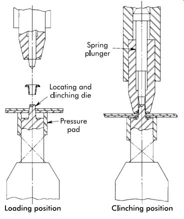
FIG. 40. Eyelet curling.
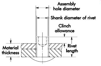
FIG. 41. Tubular riveting.
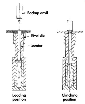
FIG. 42. Determination of rivet length for tubular rivets.
The final shape of the rivet becomes that of the tool (die) used to apply the deformation pressure. The shape may be flat (reflecting the contour of a hammer or a conventional bucking bar) or curved, as illustrated in FIGs. 40 and 10-41. The rivet die may be a simple bucking bar, interchangeable rivet set placed in the nozzle of an air hammer, or a complete forming die placed in a standard hydraulic or mechanical press.
Workholders or fixtures used to hold and locate workpieces being assembled by riveting include stationary, portable, and self-contained (riveting die fixture).
Pneumatic Hammer
Conventional riveting is performed by placing the rivet in a predrilled hole, holding a pneumatic hammer against the head of the rivet, holding a bucking bar against the end of the rivet, then cycling or activating the hammer. Initiating pres sure is exerted by the hammer while formation pressure is exerted by the bucking bar. Pneumatic hammers (rivet guns) are commercially available in a wide range of types and sizes. The nozzle of the rivet gun receives and retains the rivet set or die. Rivet sets are commercially available in a wide variety of shapes to mate with the many types of rivets commonly used.
Portable Yoke Type
Portable yoke-type riveting equipment is commonly used for squeezing large rivets (.19-1.00 in. [4.8-25.4 mm] in diameter), and consists of a yoke with a cylinder (air or oil) to provide the squeezing action. Equipment size can be minimized by using hydraulic cylinders and high pressures (5,000 lbf/in.^2 [34.5 MPa]). The weight of the equipment is minimized by using special high-strength, heat-treated steel. A cylinder advances an anvil to the rivet with a primary pressure of approximately 1,000 lbf/in.^2 (6.9 MPa). When resistance is encountered, the pressure increases to 5,000 lbf/in.^2 (34.5 MPa) for the rivet upsetting portion of the action. (FIG. 38 shows a hydraulic riveting yoke.)
Stationary Machines
Stationary machines often are used for riveting. Workpieces being assembled are located with Reference to each other (mated), and placed between the upper and lower elements of the machine.
Small stationary machines have a spring-loaded pin locator in the rivet die. Predrilled holes through the mated workpieces engage the pin locator, as illustrated in FIG. 43. The upper riveting die (backup anvil) pushes the rivet into the holes, depresses the spring pin, and upsets the driven head on the lower anvil. The rivets are fed from a hopper to a feed track. The lower end of the feed track locates the rivet directly above the pin locator. The end of the track is split to allow the upper die to pick off the rivet for insertion.
Large stationary machines often combine both riveting and hole piercing. FIG. 39 illustrated the sequence of operations. Workpieces need not be predrilled, but they must be located with Reference to each other. The locating and holding fixture may be part of the machine.
Extremely large stationary machines can hold and precisely locate large aircraft sections while thousands of holes are pierced and rivets driven.
The entire production sequence is automatic, with the machine motions governed by tape control or CNC. Closed-circuit TV is used to monitor the operation.
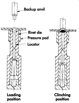
FIG. 43. Stationary riveting machine operation.
Spin Peening
Some materials to be assembled are brittle, while others require slender unsupported rivets or eyelets that will not withstand the single impact required to rivet or eyelet without distortion or cracking. In these cases, spin-peening machines may be used for delicate assembly operations. These machines deliver innumerable light blows while the hammer spins. The peening and spinning action of these machines is either mechanical or pneumatic.
Stationary Holding Fixtures
Stationary holding fixtures accommodate two or more parts located and pinned or clamped in position. They are usually freestanding fixtures where portable riveting equipment is used. Air operated riveting hammers are used for smaller rivets, such as in aircraft or appliance work.
Larger rivets used in structural work are de formed with hydraulic or air-operated riveting yokes (rivet squeezing action).
Portable Fixtures
Portable riveting fixtures are used to locate two or more parts for transport to a stationary-type rivet unit or machine. The fixtures also hold the workpieces during the riveting sequence.
Riveting Die Fixture
A riveting die fixture is completely self-contained for use in a punch press. This fixture consists of locating elements for two or more parts, and rivet buttons for driving one or several rivets in one stroke or hit of a press. The locating elements may be movable so parts can be positioned outside of the press and rivets can be placed in location.
The assembled parts are placed in location in the riveting die, and all rivets are driven at once by the action of the press. FIG. 44 illustrates a riveting die fixture.
Riveting Fixture Design
Beyond the primary requirements that the fixture precisely locate and hold workpieces, ease of loading and unloading is extremely important.
Many parts can be riveted without clamping if the weight of the parts alone will keep the riveting surfaces in contact with one another. Light-gage panels require clamps because of the tendency to warp or twist. Clamps for low-volume production are usually hand-operated cam or toggle types.
For high production, air-operated clamps of the same type are used. Locating pins and sheet holders (FIG. 45) are preferred over clamps whenever possible. The area of application must be accessible to the riveting tool, so tilting fixtures are often used.
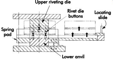
FIG. 44. Riveting die fixture.
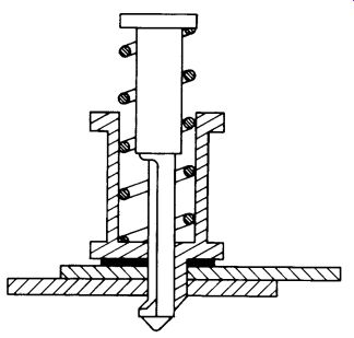
FIG. 45. Sheet holder for aligning holes during riveting.
Stapling
Stapling is a joining operation using pre formed, U-shaped wire staples. Staples are made in a variety of shapes, wire sizes, leg lengths, and crown sizes. They are available in blunt-end, chisel-point, or divergent-point styles, and are cohered into strips and sticks. The sticks are loaded manually into staplers.
FIG. 46 provides examples of staple nomenclature. Gun and hammer tackers are used to drive wire staples. Wire staples also can be driven and clinched by low-cost stapling machines.
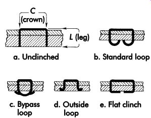
FIG. 46. Staple nomenclature.
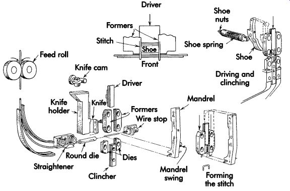
FIG. 47. Metal-stitching nomenclature and principles.
Wire stitching
Wire stitching is the process of joining two or more pieces of material with wire fed from a coil, cut to length, U-formed, driven through, and clinched by a specially designed machine called a stitcher. FIG. 47 illustrates the principle of wire-stitching machines. For low-cost, high-volume production, automatic wire-stitching machines are ideal for fastening components together. These machines are available to perform:
• carton or industrial-type stitching;
• carding, bagging, and labeling;
• book stitching; and
• metal stitching.
These machines vary in sizes from small bench to large floor models. With every stroke, the machine draws wire from a coil, cuts it to proper length, forms it into a stitch, drives it through the material, and clinches it.
Metal stitching
Metal stitching is a method of fastening thin gage metals and metals to nonmetals. Metal stitching fastens the work more economically since there is no need for other operations such as punching or drilling prior to fastening. Standard stitching machines can be tooled to form loop or flat clinches. Flat clinches are used when the stitched joint must carry heavy loads, such as in aircraft construction where joints are subject to severe stresses. The flat clinch is formed by an upward movement of the clinching die, folding the legs flat against the bottom of the material. Loop clinches provide only point contacts with the material and, therefore, less strength than flat clinches. Loop clinching is formed by curling the legs of the wire in stationary solid dies. FIG. 48 illustrates flat and loop clinches.
Other applications
Metal stitches are used extensively by manufacturers of electronic components. Variable-resistor control and switch shafts are assembled into mounting bushings by wire retaining or snap rings. The rings are made of round or flat, spring-tempered steel wire. The specially tooled machine draws the wire from a coil, cuts it to proper length, forms it into a U-shape, and drives it against a grooved die to form the round retaining ring in the circular groove of the shaft. FIG. 49 illustrates the parts and clinching dies of the retaining-ring assembly.
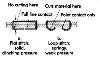
FIG. 48. Types of metal stitches.
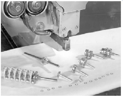
FIG. 49. C-ring retaining-ring assembly.
Staking
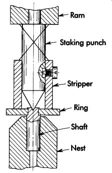
FIG. 50. Staking by center punch.
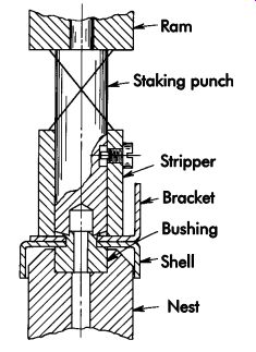
FIG. 51. Staking by ring punch.
In staking, two or more parts are joined permanently by forcing the metal edge of one member to flow either inward or outward around the other parts. Staking is an economical method of fastening parts. The operation is completed with a single stroke of an arbor, kick, punch, air, or hydraulic press. FIG. 50 illustrates locking a ring to a shaft with center-punch staking. In FIG. 51, a bushing, bracket, and shell are joined together with a ring-staking punch. FIG. 52 illustrates the principles of inward staking by forcing the metal of a ring against the knurled portion of a shaft. To provide added rigidity and torque in assembly, spot-staking may be used. It is essentially the same as ring staking except that three or more equally spaced chisel edges of the staking punch force metal into splined portions of the parts to be assembled. FIG. 53 illustrates a typical design and spot-staking punch to force metal into the spline. In some cases, it is desirable to use a combined spot- and ring-staking punch (FIG. 54).
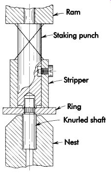
FIG. 52. Inward staking by ring punch.
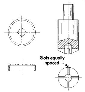
FIG. 53. Spot-staking punch and workpiece with splined hole.
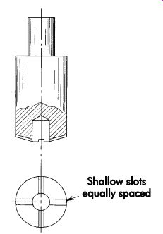
FIG. 54. Combined spot and ring-staking punch.
To facilitate efficient metal flow, the tips of punches must be free of nicks and circular grooves and, after hardening, these surfaces should be highly polished. Polishing the punch tips in the direction of metal flow, instead of circular polishing, is desirable.
Tooling for Adhesive Bonding
The design of tooling for adhesive joining does not differ greatly from that used in the physical joining process. In most cases, all standard jig and fixture components can be used.
Tooling can range in size from fixtures to hold small desktops to wing sections of a large transport plane.
The type of adhesive used is the main element to consider in the design of fixtures. Various types of adhesives are used today, all having different characteristics.
• Plural components (Class 1A) can cure at room temperature, but heating will in crease the cure rate so fixtures must with stand the required heat to start chemical reaction.
• Heat-activated (Class IB) and film adhesives (Class V) require heat to start chemical reaction.
• Moisture-cure (Class IC) adhesives cure under atmospheric moisture. Due to this moisture, tooling must be made of non-rusting material.
• Evaporative adhesives (Class II) also require heat for curing. Again, fixtures must be able to withstand higher temperatures without distortion.
• Hot-melt adhesives (Class III) are applied in a molten state, which permits high-speed production. For higher production rates, these fixtures must be easily loaded and unloaded with the use of hydraulic or pneumatic clamping.
• Delayed-tack adhesives (Class IV) are heat activated to produce a tackiness that is retained upon cooling for periods of up to several days. Fixtures must control the piece part configuration for periods of days without losing the intended holding pattern.
• Pressure-sensitive adhesives (Class VI), just as the name implies, include masking tape, surgical tape, and labels applied through the use of pressure pads or pressure rollers to form a bond.
An understanding of adhesives is important because the use of plastics is ever increasing.
Since many composites are compromised when subjected to drilling or localized compression, adhesives provide a reliable solution.
Curing Methods
Conventional methods of adhesive curing include convection and infrared-oven curing. These techniques can be troublesome due to uncontrolled temperature variation and excessive parts abuse during baking.
Cure response has been improved by induction, dielectric, and radiation (ultraviolet, microwave, electron beam, and infrared) curing.
• Induction curing uses a heating coil to energize the workpiece, rapidly increasing its temperature. The heat is conducted into the adhesive, initiating or accelerating the cure.
• Dielectric curing involves the use of a varying electric field. Electrical energy is converted into heat for the curing process.
• Radiation curing includes the use of micro waves (waves shorter than visible light) or infrared radiation (wavelengths longer than visible light) to create an adhesive cure. Ultraviolet radiation and electron beams also can be used, although electron beam curing is primarily applied to laminating and coating operations.
High processing speeds and productivity gains are possible with these methods, but capital costs to implement the processes are high.
Adhesive selection
The principal advantage of adhesive bonding is improved efficiency of production.
It is also possible to select the adhesive that best meets individual job requirements for toughness and resistance to environmental factors. The properties of the surfaces to be joined must be considered as well as the properties of the adhesive, since the substrate must uniformly coat the entire surface to create the strongest possible bond. The safety concerns of toxicity and dermatological hazards also should be addressed when selecting the appropriate adhesive.
Joint design
There are eight possible types of loading on a bond line:
1. shear,
2. peel,
3. tension/compression,
4. cleavage,
5. creep,
6. vibrational fatigue,
7. mechanical shock, and
8. thermal shock.
Adhesives generally are weak in peel and cleavage and stronger when subjected to shear and tension/compression. These characteristics should be considered when designing the workpiece.
References
Doyle, D. Criteria for Proper Adhesive Selection: From Application to Viscosity. SME Technical Paper AD90-450. Dearborn, MI: Society of Manufacturing Engineers.
Drain, K. and Schroeder, K. New Developments in Structural Adhesives. SME Technical Paper AD90-127. Dearborn, MI: Society of Manufacturing Engineers.
Tool and Manufacturing Engineers Handbook, Fourth Edition. 1983-1997. Dearborn, MI: Society of Manufacturing Engineers.
Welding and Brazing. Eighth Edition. 1971. Materials Park, OH: American Society for Metals.
Other Refs
The Society of Manufacturing Engineers (SME) has produced an introductory Workholding DVD (20 minutes), which relates directly to this section's content.
Workholding examines the principles and concepts inherent to all workholding. In addition, the program explores the various workholding options for milling and machining centers and lathes. Featured are: requirements for workholding; methods for high- and low-volume parts; machining center workholding; and the use of chucks, collets, and other lathe workholding devices.
From the Fundamentals of Tool Design video series, which comprises nine DVDs, Fixture Design (19 minutes) also relates directly to this section's content.
To correctly machine a part, it must be held in a fixturing setup that guarantees a definite location, or position, with respect to a part's datum points or surfaces. This must be repeat able, part after part. Fixture Design explores the various issues influencing the development of fixtures, as well as the basic fixture types and classifications, including milling fixtures, lathe fixtures, grinding fixtures, and broaching fixtures. The use of component kits to quickly build modular fixturing systems is also examined.
QUIZ
1. The weld backing bar is critical in the de sign of welding fixtures. From FIG. 6, determine the proper weld backing bars for the weld joints in Figure A. (Sketch the side view of the weld backing bars.)
2. Determine the depth of heat penetration on plain carbon steel using Equation 5 for induction heating. Answer a through e.
a. 5 sec
b. 10 sec
c. 20 sec
d. 45 sec
e. 60 sec
3. Calculate the spot-welding electrode-tip diameter for the following material thick nesses.
a. .062 in. (1.57 mm)
b. .1875 in. (4.763 mm)
c. .3125 in. (7.938 mm)
d. .750 in. (19.05 mm)
4. Design a welding fixture in detail for Figure B to include a complete set of drawings and bill of material. The drawings must be complete to the extent that a toolmaker could make the fixture from the drawings. Use all standard jig and fixture components where applicable.
5. Name three methods of adhesive curing.
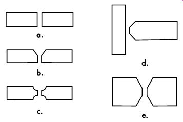
Figure A.
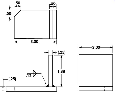
Figure B.
Home PREV. NEXT Article Index top of page