Residential electric water heaters are listed under UL Standard 174, Household Electric Storage Tank Water Heaters.
Electrical contractors many times are also in the plumbing, heating, and appliance business. They need to know more than how to do the electrical hookup. The following text discusses electrical as well as other data about electric water heaters that will prove useful.
All homes require a supply of hot water. To meet this need, one or more automatic water heaters are generally installed as close as practical to the areas having the greatest need for hot water. Water piping carries the heated water from the water heater to the various plumbing fixtures and to appliances such as dishwashers and clothes washers.
For safety reasons, in addition to the regular temperature control thermostat that can be adjusted by the homeowner, the NEC and UL Standards require that electric water heaters be equipped with a high-temperature cutoff. This high-temperature control limits the maximum water temperature to 1908F (888C). This is 208F (118C) below the 2108F (998C) temperature that causes the "temperature/pressure" relief valve to open. The high-temperature cutoff is factory preset and should never be tampered with or modified in the field. In conformance to 422.47 of the NEC, the high-temperature limit control must disconnect all ungrounded conductors.
In most residential electric water heaters, the high-temperature cutoff and upper thermostat are combined into one device, as in FGR. 5.
====
Above: FGR. 5
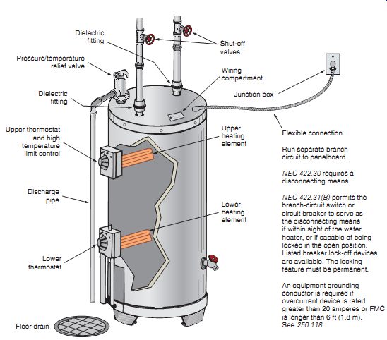
Typical electric water heater showing location of heating elements and thermostats and electrical connection:
- Pressure/temperature relief valve
- Dielectric fitting
- Dielectric fitting
- Upper thermostat and high temperature limit control
- Upper heating element
- Wiring compartment
- Junction box
- Flexible connection
Run separate branch circuit to panelboard.
NEC 422.30 requires a disconnecting means.
NEC 422.31(B) permits the branch-circuit switch or circuit breaker to serve as the disconnecting means if within sight of the water heater, or if capable of being locked in the open position.
Listed breaker lock-off devices are available. The locking feature must be permanent.
An equipment grounding conductor is required if overcurrent device is rated greater than 20 amperes or FMC is longer than 6 ft (1.8 m). See 250.118.
Lower heating element; Lower thermostat; Discharge pipe; Floor drain; Shut-off valves
====
Combination Pressure/ Temperature Safety Relief Valves
Look at FGR. 5. A pressure/temperature relief valve is an important safety device installed into an opening in the water heater tank within 6 in. (150 mm) of the top. The opening is provided for and clearly marked by the manufacturer. Many water heater pressure/temperature relief valves are factory installed, although some models still require installation of the valve by the installing contractor. Proper discharge piping must be installed from the pressure/temperature relief valve downward to within 6 in. (150 mm) of the floor, preferably near a floor drain. Terminating the discharge pipe to within 6 in. (150 mm) of the floor is important to protect people from injury from scalding water or steam discharge should the relief valve activate for any reason. This also protects electrical equipment in and around the water heater from becoming soaked should the relief valve operate.
Pressure/temperature relief valves are installed for two reasons. Their pressure/temperature sensing features are interrelated.
• Pressure: Water expands when heated. Failure of the normal temperature thermostat and the high-temperature-limiting device to operate could result in pressures that exceed the rated working pressure of the water heater tank and the plumbing system components. The relief valve, properly installed and properly rated to local codes, will open to relieve the excess pressure in the tank to the predetermined set ting marked on the relief valve. The rating is stamped on the valve's identification plate.
• Temperature: Should runaway water heating conditions occur within the water heater, temperatures far exceeding the atmospheric boiling point of water (2128F [1008C]) can take place.
Under high pressures, water will stay liquid at extremely high temperatures. For a typical municipal water supply pressure of 45 psi, water won’t boil until it reaches approximately 2908F (1438C). At 2908F (1438C), opening a faucet, a broken pipe, or a ruptured water heater tank would allow the pressure to instantly drop to normal atmospheric pressure.
The superheated water would immediately flash into steam, having about 1600 times more volume than the liquid water occupied. This blast of steam can be catastrophic, and could result in severe burns or death.
Thus, the function of the temperature portion of the pressure/temperature relief valve is to open when a temperature of 2108F (998C) occurs within the water heater tank. Properly rated and maintained, the pres sure/temperature relief valve will allow the water to flow from the water heater through the discharge pipe at a rate faster than the heating process, thereby keeping the water temperature below the boiling point.
Should the cold water supply be shut off, the relief valve will allow the steam to escape without undue buildup of temperature and pressure in the tank.
Requirements for relief valves for hot water supply systems are found in the ANSI Standard Z21.22.
Sizes:
Residential electric water heaters are available in many sizes, such as 6, 12, 15, 20, 30, 32, 40, 42, 50, 52, 66, 75, 80, 82, 100, and 120 gallons.
Corrosion of Tank
To reduce corrosion of the steel tank, most water heater tanks are glass lined. Glass lining is a combi nation of silica and other minerals (rasorite, rutile, zircon, cobalt, nickel oxide, and fluxes). This special mix is heated, melted, cooled, crushed, then sprayed onto the interior steel surfaces and baked on at about 16008F (8718C). To further reduce corrosion, aluminum or magnesium anode rods are installed in special openings, or as part of the hot water outlet fitting, to allow for the flow of a protective current from the rod(s) to any exposed steel of the tank.
This is commonly referred to as cathodic protection.
Corrosion problems within the water heater tank are minimized as long as the aluminum or magnesium rod(s) remain in an active state. Anodes should be inspected at regular intervals to determine when replacement is necessary, usually when the rod(s) is reduced to about one-third of its original diameter, or when the rod's core wire is exposed. Further information can be obtained by contacting the manufacturer, and consulting the installation manual.
Some water heater tanks are fiberglass or plastic lined.
Heating Elements:
The wattage ratings of electric water heaters can vary greatly, depending on the size of the heater in gallons, the speed of recovery desired, local electric utility regulations, and codes. Typical wattage ratings are 1500, 2000, 2500, 3000, 3800, 4500, and 5500 watts.
A resistance heating element might be dual rated. For example, the element might be marked 5500 watts at 250 volts, and 3800 watts at 208 volts.
Most residential-type water heaters are connected to 240 volts except for the smaller 2-, 4-, and 6-gallon point of use sizes generally rated 1500 watts at 120 volts. Commercial electric water heaters can be rated single-phase or 3-phase, 208, 240, 277, or 480 volts.
UL requires that the power (wattage) input must not exceed 105% of the water heater's nameplate rating. All testing is done with a supply voltage equal to the heating element's rated voltage. Most heating elements may burn out prematurely if operated at voltages 5% higher than for which they are rated.
To help reduce the premature burnout of heating elements, some manufacturers will supply 250-volt heating elements, yet will mark the name plate 240 volts, with its corresponding wattage at 240 volts. This allows a safety factor if slightly higher than normal voltages are experienced.
Heating Element Construction:
Heating elements generally contain a nickel chrome (nichrome) resistance wire embedded in compacted powdered magnesium oxide to ensure that no grounds occur between the wire and the sheath. The magnesium oxide is an excellent insulator of electricity, yet it effectively conducts the heat from the nichrome wire to the sheath.
The sheath can be made of tin-coated copper, stainless steel, or an iron-nickel-chromium alloy.
The latter alloy comes under the trade name of Incoloy. The stainless steel and Incoloy types can withstand higher operating temperatures than the tin-coated copper elements. They are used in premium water heaters because of their resistance to deterioration, lime scaling, and dry firing burnout.
High watt density elements generally have a U-shaped tube, and give off a great amount of heat per square inch of surface. FGR. 6(A) illustrates a flange-mounted high-density heating element.
FGR. 6(B) illustrates a high-density heating element that screws into a threaded opening in the tank. High-density elements are very susceptible to lime-scale burnout.
Low watt density elements, as in FGR. 6(C), generally have a double loop, like a U tube bent in half. They give off less heat per in.^2, have a longer life, and are less noisy than high-density elements.
An option offered by at least one manufacturer of electric water heaters is a dual-wattage heating element. A dual-wattage heating element actually contains two heating elements in the one jacket.
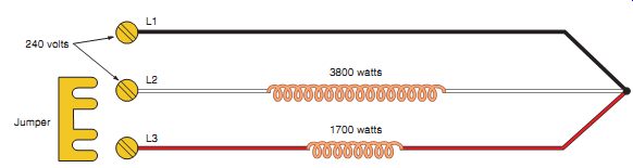
One element is rated 3800 watts and one element is rated 1700 watts. Three leads are brought out to the terminal block. The 3800-watt heating element is connected initially, with the option of connecting the second 1700-watt heating element if the wiring to the water heater is capable of handling the higher total combined wattage of 5500 watts. To attain the higher wattage, a jumper (provided by the manufacturer) is connected between two terminals on the terminal block, FGR. 7.
Any electric heating element coated with lime scale may be noisy during the heating cycle. Limed up heating elements should be cleaned or replaced, following the manufacturer's instructions.
Don’t energize the electrical supply to a water heater unless you are sure it’s full of water. Most water heater heating elements are designed to operate only when submersed in water.
Residential electric water heaters are avail able with one or two heating elements. FGR. 5 shows two heating elements. Single-element water heaters will have the heating element located near the bottom of the tank. If the water heater has two heating elements, the upper element will be located about two-thirds of the way up the tank.
===
Above: FGR. 7
A dual-wattage heating element. The two wires of the incoming 240-volt circuit are connected to L1 and L2. These leads connect to the 3800-watt element. To connect the 1700-watt element, the jumper is connected between L2 and L3. With both heating elements connected, the total wattage is 5500 watts.
240 volts 1700 watts 3800 watts L1 L2 L3 Jumper
===
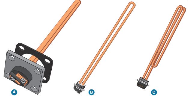
Above: FGR. 6 Heating elements.
===
Speed of Recovery
Speed of recovery is the time required to bring the water temperature to satisfactory levels in a given length of time. The current accepted industry standard is based on a 908F (32.228C) rise. For example, referring to TBL. 1, we find that a 3500-watt element can raise the water temperature 908F (32.228C) of a little more than 16 gallons an hour. A 5500-watt element can raise water temperature 908F (32.228C) of about 25 gallons an hour. Speed of recovery is affected by the type and amount of insulation surrounding the tank, the sup ply voltage, and the temperature of the incoming cold water.
TBL. 2 shows the approximate time it takes to run out of hot water using typical shower heads with various storage capacity residential electric water heaters. Current standards for new shower heads are typically 2.5 gallons per minute. When the flow restrictors are removed, the flow rate can increase to 6-18 gallons per minutes per shower head. There are very low-flow-rate showerheads available in the range of 1-2 gallons per minute. All of this depends on the water pressure.
An easy way to determine a showerhead's flow rate is to turn on the water, hold a large bucket of known capacity under it, and time how long it takes to fill the bucket.
====
TBL. 1
Electric water heater recovery rate per gallon of water for various wattages.
HEATING ELEMENT WATTAGE
GALLONS PER HOUR RECOVERY FOR INDICATED
TEMPERATURE RISE
Notes: If the incoming water temperature is 408F (Northern states), use the 808 column to raise the water temperature to 1208F.
If the incoming water temperature is 608F (Southern states), use the 608 column to raise the water temperature to 1208F.
For example, approximately how long would it initially take to raise the water temperature in a 42-gallon electric water heater to 1208F where the incoming water temperature is 408F? The water heater has a 2500-watt heating element.
Answer: 42 4 12.9 5 3.26 hours (approximately 3 hours and 16 minutes).
To keep this table simple, noncluttered, and easy to read, only Fahrenheit temperatures are shown.
====
TBL. 2
This chart shows the approximate time in minutes it takes to run out of hot water when using various shower heads, different incoming water temperatures, and different capacity water heaters.
LENGTH OF CONTINUOUS SHOWER TIME-IN MINUTES- FOR TYPICAL SIZES OF RESIDENTIAL ELECTRIC WATER HEATERS.
CHART BASED ON 70% DRAW EFFICIENCY. RECOVERY RATE IS NOT Above: Fig. D IN BECAUSE IT IS NORMALLY NOT A FACTOR IN CONTINUOUS DRAW OF WATER SITUATIONS.
Example #1: A 40-gallon electric water heater has a 408F incoming water supply. How many minutes can a 3 GPM shower head be used to obtain 1058F hot water? Answer: 11 minutes Example #2: A residence has an 80-gallon electric water heater. The incoming water supply is approximately 608F. How many minutes can two 2 GPM shower heads be used at the same time to obtain 1058F hot water? Hint: Two 2 GPM shower heads are the same as one 4 GPM shower head.
Answer: 19 minutes
====
Scalding from Hot Water
The following are plumbing code issues but are discussed briefly because of their seriousness.
Temperature settings for water heaters are problematic! Set the water heater thermostat high enough to kill bacteria on the dishes in the dishwasher and possibly get scalded in the shower. Or set the thermostat to a lower setting and not get scalded in the shower, but live with the possibility that bacteria will still be present on washed dishes.
The Consumer Product Safety Commission (CPSC) reports that 3800 injuries and 34 deaths occur each year due to scalding from excessively hot tap water. Unfortunately, the victims are the elderly and children under the age of 5. They recommend that the setting should not be higher than 1208F (498C). Some state laws require that the thermostat be preset at no higher than 1208F (498C). Residential water heaters are all preset by the manufacturer at 1208F (498C).
Manufacturers post caution labels on their water heaters that read something like this:
SCALD HAZARD: WATER TEMPERATURE OVER 1208F (498C) CAN CAUSE SEVERE BURNS INSTANTLY OR DEATH FROM SCALDS. SEE INSTRUCTION MANUAL BEFORE CHANGING TEMPERATURE SETTINGS.
To reduce the possibility of scalding, water heaters can be equipped with a thermostatic non-scald mixing valve or pressure-balancing valve that holds a selected water temperature to within one degree regardless of incoming water pressure changes. This prevents sudden unanticipated changes in water temperatures.
TBL. 3 shows time/temperature relationships relating to scalding.
What about Washing Dishes?
Older automatic dishwashers required incoming water temperature of 1408F (608C) or greater to get the dishes clean. A water temperature of 1208F (498C) is not hot enough to dissolve grease, activate power detergents, and kill bacteria. That is why commercial and restaurant dishwashers boost temperatures to as high as 1808F (828C).
Newer residential dishwashers have their own built-in water heaters to boost the incoming water temperature in the dishwasher from 1208F (498C) to 1408F-1458F (608C-638C). This heating element also provides the heat for the drying cycle. Today, a thermostat setting of 1208F (498C) on the water heater should be satisfactory.
===
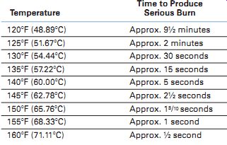
TBL. 3
Time/temperature relationships related to scalding of an adult subjected to moving water. For children, the time to produce a serious burn is less than for adults. (Shriners Burn Institute, Cincinnati Unit)
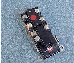
Above: FGR. 8
Typical electric water heater controls. The 7-terminal control combines water temperature control plus high-temperature limit control. This is the type commonly used to control the upper heating element as well as provide a high-temperature-limiting feature. The 2-terminal control is the type used to control water temperature for the lower heating element.
(THERMO-DISC, Inc., subsidiary of Emerson Electric)
===
Thermostats/High-Temperature Limit Controls
All electric water heaters have a thermostat(s) and a high-temperature limit control(s).
Thermostats and high-temperature limit controls are available in many configurations. They are available as separate controls and as combination controls.
FGR. 8 illustrates a combination thermostat/high-temperature limit control. This particular control is an interlocking type sometimes referred to as a snap-over type. It’s used on 2-element water heaters and controls the upper heating element as well as providing the safety feature of limiting the water temperature to a factory-preset value. Another thermostat is used to control the lower heating element. When all of the water in the water heater is cold, the upper element heats the upper third of the tank. The lower thermostats are closed, calling for heat, but the interlocking characteristic of the upper thermostat/high limit won’t allow the lower heating element to become energized. With this connection, both heating elements cannot be on at the same time.
This is referred to as non-simultaneous or limited demand operation.
When the water in the upper third of the tank reaches the temperature setting of the upper thermostat, the upper thermostat "snaps over," completing the circuit to the lower element. The lower element then begins to heat the lower two-thirds of the tank. Most of the time, it’s the lower heating element that keeps the water at the desired tempera ture. Should a large amount of water be used in a short time, the upper element comes on. This pro vides fast recovery of the water in the upper portion of the tank, which is where the hot water is drawn from the tank.
Safety Note: Most residential water heater thermostats are of the single-pole type. They don’t open both ungrounded conductors of the 240 volt supply. They open one conductor only, which is all that is needed to open the 240-volt circuit to the heating element. What this means is that a reading of 120 volts to ground will always be present at the terminals of the heating element on a 240-volt, single-phase system such as found in residential wiring. If the heating element becomes grounded to the metal sheath, the element can continue to heat even when the thermostat is in the "OFF" position because of the presence of the 120 volts.
The high-temperature limit control opens both ungrounded conductors.
Various Types of Electrical Connections
There are many variations for electric water heater hookups. Most electric utilities have their own unique time-of-use programs and specific electrical connection requirements for electric water heaters. It’s absolutely essential that you contact your local electric utility for this information.
Because of the cumulative large power consumption of electric water heater loads, electric utilities across the country have been innovative in creating special lower rate structures (pro grams) for electric water heaters, air conditioners, and heat pumps. Electric utilities want to be able to shed some of this load during their peak periods. They will offer the homeowner choices of how the water heater, air conditioner, or heat pump is to be connected and, in some cases, will provide financial incentives (lower rates) to those who are willing to use these restricted "time-of day" connections. "Time-of-day," "time-of use," and "off-peak" are terms used by different utilities. If homeowners have a large-storage-capacity electric water heater, they will have an adequate supply of hot water during those periods of time the power to the water heater is off. If they can not live with this, they have other options. Check with the local power company for details on their particular programs.
The following text discusses some of the methods in use around the country for connecting electric water heaters, and in some cases air-conditioning and heat pump equipment.
Utility Controlled
The world of electronics has opened up many new ways for an electric utility to meter and control residential electric water heater, air-conditioning, and heat pump loads. Electronic watt-hour meters can be read remotely, programmed remotely, and can detect errors remotely. The options are endless.
The utility can install watt-hour meters that combine a watt-hour meter and a set of switching contacts. The contacts are switched on and off by the utility during peak hours, using a power line carrier signal. Older style versions of this type of watt-hour meter incorporated a watt-hour meter, time clock, and switching contacts. The time clock would be set by the utility for the desired times of the On-Off cycle. Today, the metering and the programming for timing and control of the On-Off cycling is accomplished through electronic devices.
Electronic meters contain an optical assembly that scans the rotating disc and a microprocessor that records the number of turns and speed of the disc. These electronic digital meters can record the energy consumption during normal hours and during peak hours, allowing the electric utility to bill the homeowner at different rates for different periods of time. One type of residential single phase watt-hour meter can register four different "time-of-use" rates. This type of meter is shown in Figure 29-2.
One major utility programs their residential meters for "peak periods" from 9 am to 10 pm, Monday through Friday-except for holidays.
Their "off-peak" periods are weekend days and all other hours. Programming of electronic meters can extend out for more than 5 years. The possibilities for programming electronic meters are endless.
Older style mechanical meters used gears to record these data, and did not have the programming capabilities that electronic meters do as in Fgrs 9, 10, and 11.
The switching contacts in the meter are connected in series with the water heater, air conditioner, or heat pump load that is to be controlled for the special "time-of-day" rates, Fgrs 9, 10, and 11. The utility determines when they want to have the electric water heater on or off.
FGR. 9 shows a separate combination meter/time clock for the electric water heater load. The utility sets the clock to be "OFF" during their peak hours of high power consumption. Thus the term off-peak metering. Off-peak metering is oftentimes called "time-of-use" or "time-of-day" metering. In exchange for lower electric rates, the homeowner runs the risk of being without hot water. Should homeowners run out of hot water during these off periods, they have no recourse but to wait until the power to the water heater comes on again. For this type of installation, large-storage-capacity water heaters are needed so as to be able to have hot water during these periods.
=== 
Above: FGR. 9
Wiring for a typical "off-peak" electric water heater circuit. A separate watt-hour meter/time clock controls the circuit to the water heater. The utility sets the time clock to turn the power off during certain peak periods of the day. This type of circuitry is called "time-of-day" programming.
----
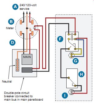
Above: Fgr 10.
240/120-volt service Main watt-hour meter Water heater watt-hour
meter Service conductors to main panelboard Two-pole disconnect switch or
circuit breaker Combination high temperature limit and upper interlocking
thermostat Upper heating element Lower thermostat Lower heating element Notations
used in Fgrs 9, 10, 12,
and 13.
===
MAIN
Neutral Meter 240/120-volt service Double-pole circuit breaker connected to main bus in main panelboard
Above: FGR. 10 The meter contains a set of contacts that can be controlled by the utility.
The water heater circuit is fed from the main panelboard, through the contacts, then to the water heater.
----

Above: FGR. 11
In this diagram, the utility sends a radio signal to the relay, which in turn can "shed" the load of a residential water heater, air conditioner, or heat pump. If the relay has two sets of contacts, four conductors would be required. Low-voltage relays are also used, in which case low-voltage conductors are run between the radio control unit and relay in the appliance. For the control of an air conditioner or heat pump, the radio control unit is connected "in series" with the room thermostat.
This arrangement can be used with one watt-hour meter, using a sliding rate schedule with a "time-of-day" control. Contact the electric utility for technical data regarding how it wants the electrical connections to be made for its particular programs.
Relay Utility can turn the water heater on and off by sending a radio signal to the relay MAIN Branch circuit WATER HEATER
===
FGR. 10 illustrates a type of meter that contains an integral set of contacts, controlled by the utility via signals sent over the power lines.
These meters are available with either 30-ampere or 50-ampere contacts, the contact rating selected to switch the load to be controlled. The electric utility determines when to shed the load. The home owner must be willing to live with the fact that the power to the water heater, air conditioner, or heat pump might be turned off during the peak periods.
In FGR. 11, the utility mounts a radio controlled relay to the side of the meter socket.
One major utility using this method makes use of 10 different radio frequencies. When the utility needs to shed load, it can signal one or all of the relays to turn the water heater, air conditioner, or heat pump load off and on. This might only be a few times each year, as opposed to time-clock programs that operate daily. This method is a simple one. One watt-hour meter registers the total power consumption. The homeowner signs up for this program. The program offers a financial incentive, and the homeowner knows up front that the utility might occasionally turn off the load during crucial peak periods.
Customer Controlled
There are some rate schedules where customers can somewhat control their energy costs by doing their utmost to use electrical energy during off-peak hours. For example, they would not wash clothes, use the electric clothes dryer, take showers, or use the dishwasher during peak (premium) hours. The choice is up to homeowners. To accomplish this, watt-hour meters can be installed that have two sets of dials: one set showing the total kilowatt hours, and the second set showing premium time kilowatt hours. See Figure 29-2. With this type of meter, the utility will have the total kilowatt hours used as well as the premium time kilowatt hours used. With this information, the utility bills customers at one rate for the energy used during peak hours, and at another rate for the difference between total kilowatt hours and premium time kilowatt hours. The electric utility will determine and define premium time.
Some homeowners have installed time-clocks on their water-heater circuit to shut off during peak premium time hours to be sure they are not using energy during the periods with a high rate per kilowatt-hour.
Uncontrolled
The simplest and most common uncontrolled method is shown in FGR. 12. There are no extra meters, switching contacts in the meter, extra disconnect switches, or controllable relays. The water heater circuit is connected to a 2-pole branch-circuit breaker in the main distribution panelboard. The electrical power to the water heater is on 24 hours a day. This is the connection for the water heater in the residence in this text. Instead of separate "low-rate" metering that requires an additional watt-hour meter, the utility offers a sliding scale of rate steps.
State, local, and applicable regulatory taxes would be added to the amount due.
Certain utilities will use the higher energy charge during the June, July, August, and September summer months.
Another uncontrolled method is to use two watt hour meters, FGR. 13. The water heater has power 24 hours per day. One meter will register the normal lighting load at the regular residential energy charge. The second meter will register the energy consumed by the water heater, air conditioner, or heat pump at some lower energy rate.
Are Water Heater Control Conductors Permitted in the Same Raceway as Service-Entrance Conductors?
Conductors other than service-entrance conductors are not permitted in the same raceway as the service-entrance conductors, 230.7. However, Exception No. 2 to this section does permit load management control conductors that have over current protection to be installed in the service raceway.
====

Above: FGR. 12 Water heater connected to 2-pole circuit in Main Panelboard.
MAIN Neutral Meter 240/120-volt service Two-pole circuit breaker connected to main bus in main panelboard Kilowatt-hour power consumption of water heater is metered by same meter used for normal household loads. Only one meter is required. Power rates are usually on a sliding scale; that is, the more power in kilowatt-hours used, the lower rate per kilowatt-hour.
====
EXAMPLE
Meter reading 06-01-20XX 00532 Meter reading 05-01-20XX 00007 Total kilowatt-hours used 00525 Basic monthly energy charge $11.24 1st 400 kWh × 0.10206 40.82
Next 125 kWh × 0.06690 8.36 Amount Due $60.42
====