AMAZON multi-meters discounts AMAZON oscilloscope discounts
Process Task
In most thermoplastic extrusion operations, the basic function of the extruder is to accept a product, melt it through a combination of mechanical and thermal energy, and generate sufficient pressure to pass the molten polymer through a die. Sometimes the product is fed to the extruder in the form of a melt. In these cases, the task of the extruder is limited to providing additional energy input for homogenizing the melt with other ingredients and then to generate sufficient pressure to pass the molten material through a die. Other process tasks include
++devolatilization of residual monomers, solvents, water, etc.
++chemical reactions such as polymerization, polycondensation, polyaddition
++polymer alloying and blending
++incorporation of fibers (glass, carbon, etc.) for reinforcing
Screw extruders are applied in many areas outside of the plastics industry, for example:
++food processing (extrusion cooking of starch-based raw materials)
++energetic materials (mixing and forming of propellants)
++adhesives and sealants (compounding and feeding of coating equipment)
++chemicals and pharmaceuticals (reactive processing)
++hazardous waste treatment (encapsulating, solidification)
Design Feature- Single-Screw Extruders
A helical screw that rotates inside a cylindrical barrel housing can be referred to as a single-screw extruder. The screw consists of three sections: feeding, compression, and metering.
The feed section consists of deep screw flights designed to accommodate feed intake of low-bulk-density powders or pellets. Single-screw extruders usually operate with the feed section filled 100 percent (flood feeding); less than 100 percent fill in the feed section is called starve-feeding.
The compression section (sometimes referred to as the transition zone) is designed to input mechanical energy for melting, cooking, etc. Compression ratio is the term used to describe the ratio of flight depth or pitch in the feed zone to flight depth or pitch in the metering zone; typical compression ratios are from 1:1 to 5:1. There are two basic design approaches to achieve compression:
1. increase root diameter (decreasing flight depth)
2. decrease pitch, constant root diameter (constant flight depth)
The metering section is located before the die restriction. Most of the mechanical energy dissipation occurs in the metering section, producing the highest temperature in the extruder, high shear rates, and mixing. Enhanced mixing is achieved in the metering section with interrupted flights, mixing pins, screw barriers, etc.
The barrel housing may be grooved on the inner surface to improve frictional characteristics in the feed zone. Small grooves are cut into the barrel wall, either straight (axially down the barrel length) or spiral (helical grooves cut opposite to the conveying direction of the screw).
Several hybrid single-screw extruder designs are available; one incorporates a single screw that reciprocates as it rotates. Fixed pins on the barrel fit between interruptions in screw flights to promote mixing within the screw channel with each revolution. Some designs provide blades instead of pins, which can be adjusted to more or less restrict flow, depending on the angular position of the blade; shear intensity can be varied to suit the process application.
Design Features- Twin-Screw Extruders
Twin-screw extruders can be classified according to the direction of screw rotation and to the amount the screws intermesh with each other (FIG. 9). A screw system that is lengthwise open (down channel) has a passage from the inlet to the outlet of the machine. Material exchange can take place lengthwise in the screw channel. In a lengthwise closed design, the screw flights in the longitudinal direction are closed at intervals. Crosswise open channels allow material exchange from one flight to another; in crosswise closed channels no material transfer is possible (neglecting mechanical clearances). Whether the screws are open lengthwise or crosswise or have a closed geometry has a direct effect on conveying characteristics, mixing, and pressure-generating capacity of the screw system.
Non-intermeshing twin-screws extruders are closest in principle to single-screw extruders. Two screws are arranged next to each other with the center line distance a little greater than the screw diameter; the screws can rotate at the same or different speeds. The interaction of the screws is limited to a random passage of material from one screw to the other (non-intermeshing screws are open both lengthwise and crosswise). Non-intermeshing systems are available with co-rotating or counter-rotating screws.
Fully intermeshing twin-screw systems can be co-rotating (both screws turn in the same direction) or counter-rotating (screws turn opposite, either toward or away from each other at the tip of the extruder). Fully intermeshing, counter-rotating twin-screw extruders are characterized as lengthwise and crosswise closed, similar to a screw pump. Fully intermeshing, co-rotating twin-screw extruders are lengthwise open and can be crosswise closed with conveying screws or crosswise open when staggered screw discs are used. Fully intermeshing twin-screws are also known as self-wiping.
Partially intermeshing twin-screw extruders are lengthwise open and can be crosswise closed (counter rotating) or crosswise open (co-rotating or counter-rotating). The degree of interaction between the screws is more pronounced than the non-intermeshing systems.
Twin-screw machines are now available that can operate both as a co-rotating and counter-rotating extruder using the same gearbox; a lever device is mounted on the gearbox to change rotation, and the appropriate screws are installed. Another twin-screw system that is not shown in FIG. 9 is a fully intermeshing, counter-rotating conical screw system. The screw diameters decrease from the feed toward the discharge. This system provides a large free volume for feeding low-bulk-density materials and a large heat transfer surface area.
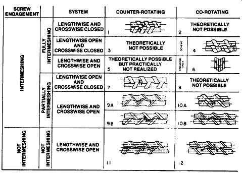
FIG. 9 Screw meshes and configurations. (Werner & Pfleiderer Corporation,
Ramsey, NJ.)
Single-Screw versus Co-Rotating versus Counter-Rotating
Feeding and Conveying of Solids
When fed with a solid, conveying is the first extrusion operation. Like any screw conveyor, an extruder operates on the principle of frictional relationships between a solid and the surrounding barrel walls. In order to analyze solids conveying, a force balance has to be made. The balance of the frictional forces determines the solid plug transport.
The driving force is the friction between the barrel surface and the plug and is proportional to the pressure exerted by the plug on the barrel. The retarding forces are friction forces on the flights and the root of the screw.
An increased coefficient of friction between the plug and the barrel wall (such as barrel grooves) and a lower coefficient of friction at the flights and the root of the screw (smooth screw) will result in better solids conveying. This conveying mechanism applies both to single- and twin-screw systems.
Single-screw extruders have deep-cut flights in the feed section to maximize volumetric capacity. Throughput is influenced by screw speed, since flood-feeding is commonly used. Barrel grooves improve frictional relationship for solids conveying.
Counter-rotating twin-screw extruders turn outward at the top, inward at the bottom (if the screws turned inward on top, the material would have to be pulled in by the calendar gap formed between the screws). The material is conveyed to the lower wedge where it is partially compressed and conveyed as a unit volume.
In order to utilize the largest possible free volume, multi-flighted deep-cut screws are used. Since the conveying principle of the counter-rotating screws forms closed chamber unit volumes, this machine is ideal for feeding solids. The entire free volume can be utilized, assuming optimum pitch angle.
Co-rotating twin-screw extruders convey material from one screw toward the lower wedge, where the material is compressed and then picked up by the other screw and conveyed further. The flow path is then a figure-eight shape, material being continuously transferred from one screw to the other around the periphery as it moves downstream.
Melting Process
The melting process in all screw machines can be divided into two sections:
1. Compacting of the solids to eliminate air pockets. The air in most cases escapes through the feed opening. Simultaneously, a melt film is formed on the barrel walls; the material fuses due to heat and pressure.
2. Generation of melt through sheafing of the material and mixing of the unmolten particles with the already formed melt. As a result, a large heat exchange surface is generated between the solid particles and the melt.
Single-screw extruders achieve compaction in the compression section of the screw where air is forced back to the feed opening. A melt film on the barrel wall is scraped off by the pushing side of the screw flank. The melt pool collects in front of the pushing flank.
Fully intermeshing, counter-rotating twin-screw extruders with tight clearances cannot efficiently compress the air out of the closed chambers toward the feed opening. Loose clearances are intentionally created for this reason. Solid particles are drawn into the wedge area and softened; the plasticized mass is taken in by the calendar gap and collected at the trailing flank.
Solids compression in co-rotating twin-screw extruders is produced through flow restriction. Reverse pitch screw elements or staggered screw discs are used to convey in the opposite direction, causing a pressure build-up upstream of the reverse pitch section. Air is allowed to flow back toward the feed, since the system is lengthwise open. Melting results from the backup length generated by the reverse pitch section.
Venting
Removal of volatiles, moisture, or entrapped air is commonly practiced in single- and twin-screw extruders. Screw geometry, vent port design, and process parameters will vary for venting on single-screw, co-rotating, and counter-rotating twin-screw extruders. Vent ports can be operated atmospherically or under vacuum, depending on the amount of volatiles to be removed.
Single-screw extruders use reduction of pitch or flight depth (increase in root diameter) prior to vent ports to produce a pressure drop for venting. The degree of fill under the vent is less than 100 percent, preventing material from being forced out of the screw. Downstream of the vent(s), the screw must have another compression zone and metering zone to overcome die pressure.
Counter-rotating twin-screw extruders have a reduced pitch prior to the vent opening to create a pressure drop under the vent where pitch may be increased again.
Non-intermeshing (tangential) designs turn into one another at the top and drag material away from the vent opening. Lengthwise and crosswise closed channels on fully intermeshing counter-rotating extruders create melt sealing for vacuum venting. Fully intermeshing counter-rotating screws turning away from each other also prevent material from being forced out of the screw channels.
Co-rotating twin-screw extruders use reverse pitch screw elements or staggered screw discs to form a restriction in the screw. Conveying screws upstream of the restriction must overcome this resistance, resulting in a pressure drop in the vent area. Large pitch screws are installed in the vent section to provide a low degree of fill.
Several types of vent ports are used to keep the up-turning side of the screw(s) covered, preventing material from being forced out of the vent opening. Mechanical vent "stuffers" are available to keep material in the screw flights while under vacuum.
Pressure-Generating Capacity
The pressure-generating capacity of an extruder is a function of the screw geometry.
Single-screw extruders have lengthwise open channels; pressure is generated by the metering section. Single-screw machines generally use the entire screw length to overcome die resistance (100 percent degree of fill throughout extruder). Fully intermeshing, counter-rotating twin-screw extruders provide positive displacement through tight clearances. Closed chamber volumes intermittently releasing may lead to pressure fluctuations; enlarged clearances are sometimes used to overcome these pulsations, which also decreases positive-displacement capabilities.
Fully intermeshing, co-rotating twin-screw systems provide partial positive conveying through the wedge resistance. Material viscosity plays an important role in pressure build-up where a lengthwise open channel exists. Due to downstream restrictions, such as dies, the melt accumulates along the screw channel upstream, over several turns of the screw. Back-up length (zone of 100 percent degree of fill) is a function of material viscosity, screw geometry, and die resistance.
Process Variables
Process optimization on screw extruders requires special attention to the interaction of process variables and their influence on process parameters.
Length/diameter (L/D) ratio is used to characterize extruder size. Diameter refers to outside screw diameter, length refers to the effective barrel length. Single- and twin-screw extruders are available from L/D = 3 to L/D = 48. The L/D ratio is kept constant for geometric scale-up. Residence time is a function of extruder L/D ratio.
Screw geometry is a key factor in extruder performance. Screw configuration will influence residence time, mixing quality, specific energy input, discharge temperature, and degree of fill.
Single screw compression ratio, length of metering zone, and other geometric variables are well documented and predictable for thermoplastic processing.
Barrier-type screws permit melt recirculation to improve melting and mixing performance.
Counter-rotating twin-screw extruders require selection of screw pitch, clearances between screws and between screw and barrel, and flight width. Interrupted flights are also used to enhance mixing.
Co-rotating twin-screw extruders offer different pitches and conveying directions (fight or left hand); additional shear/mixing is provided with staggered screw discs (kneading discs). These mixing elements have various widths and stagger angles to influence mixing intensity and residence time distribution (FIG. 10). Screw speed has a direct influence on mixing quality, specific energy input, residence time, and degree of fill. Single-screw and co-rotating twin-screw extruders can operate at 300 to 500 RPM; counter-rotating twin-screw extruders and very large co-rotating twin-screw extruders run much slower due to mechanical limitations (FIG. 11).
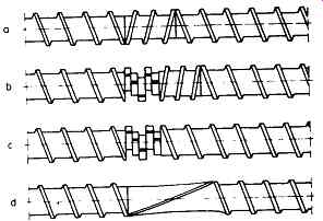
FIG. 10 Different screw arrangements in the plasticizing zone of a twin-screw,
co-rotating extruder: (A) left-hand screw; (B) right-hand kneading block,
left-hand screw; (C) right-hand kneading block; (D) large pitch left-hand
screw. (Werner & Pfleiderer Corporation, Ramsey, NJ. )
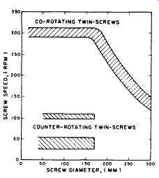
FIG. 11 Commercially common screw speeds for twin-screw machines. (Werner & Pfleiderer
Corporation, Ramsey, NJ.)
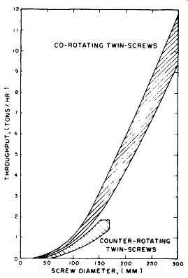
FIG. 12 Common throughputs for twin-screw machines.
Throughput is used as an independent variable on twin-screw extruders; throughput is dependent on screw speed in single-screw extruders that are flood-fed.
Throughput affects degree of fill, residence time, specific energy input, and mixing quality. Common throughputs for twin-screw machines are shown in FIG. 12.
Barrel temperature has an effect on specific energy input and discharge temperature. The temperature profile can influence material viscosity, effectively thinning or building viscosity in the extruder screw. Extruders processing high-temperature polymers operate with barrel temperatures at 400 to 500 degree extruders used for intensive cooling have glycol solution circulating through the barrel jackets and screw shafts at -15 C. Die pressure can have a significant impact on extruder performance. Open channel screws will have difficulties in generating high pressure with a very low viscosity product, where a closed screw channel will have no problem. Die pressure can be used as a variable in this way to influence degree of fill (called backup length), residence time, and specific energy input (open channel machines). Extrusion pressures for plastics processing are in the range of 500 to 3500 psi. Screw extruder designs are available for continuous service ratings of 9000 psi.
Process Parameters
The combination of extruder process variables produces a unique set of process parameters (residence time distribution, specific energy input, heat transfer, mass transfer, and degree of fill) responsible for a given product quality. The objective in scale-up is to reproduce those unique process parameters at a higher rate with larger equipment.
Residence Time
Residence time distribution (RTD) in a screw extruder is a compromise between an ideal tubular reactor (plug flow) and a cascade of ideally mixed stirred tank reactors.
The RTD of a screw extruder is more plug-like than a pipe of comparable L/D. Single screw, non-intermeshing and partially intermeshing twin-screw extruders are not self-cleaning and exhibit long residence time tails. Fully intermeshing twin-screw extruders are self-cleaning; residence time distribution is sharply defined.
Axial mixing in a longitudinal direction is shown in the width and length of the residence time distribution curves.
Average residence times can vary from less than ten seconds (short extruder, high speed) to more than ten minutes (long extruder, slow speed, low throughput).
Specific Energy
Specific energy input is defined as kilowatt-hours per kilogram (or horsepower-hours per pound) and describes the mechanical energy introduced into the product by the screw (specific mechanical energy) and thermal energy through the barrel jacket (specific thermal energy). Specific energy is a function of degree of fill, screw design, extruder length (L/D), and temperature.
Heat Transfer
Heat transfer in screw extruders occurs between the material in the screw channel and the barrel wall (or through the screw shaft for additional heat transfer surface area). Screw geometry and extruder design play a decisive role in achieving good heat transfer. Fully intermeshing co-rotating and counter-rotating twin-screw extruders provide constant renewal of material layers in the screw channel; multi-flighted screw systems provide shallow flight depths for better conductive heat transfer. Measurements with polymer melts on fully intermeshing, co-rotating twin-screw extruders have given heat transfer values of 200 to 500 kcal/m 2 hr degree
Mass Transfer
Devolatilization of solvents, monomers, reaction products, or water is accomplished on screw extruders with the use of vent port openings in the barrel. Volatiles can be removed atmospherically or under vacuum, depending on the process requirements.
Limiting factors for mass transfer in screw extruders are equilibrium volatile content, residence time in the vent, vapor velocity (vent open area), and film thickness in the screw channel. Devolatilizing extruders usually have several vents to provide staged vacuum strength, increased residence time, and maximum open area. Single-screw extruders use shallow flight depths, while twin-screw extruders use large screw pitch under the vents to produce thin film thickness (low degree of fill) for enhanced mass transfer.
Degree of Fill
The degree of fill in screw extruders is influenced by a combination of process variables. Single-screw extruders are typically 100 percent filled throughout the screw length (except for venting extruders), while twin-screw extruders operate at anywhere from 20 to 100 percent fill along the screw length. Degree of fill is manipulated by screw geometry (forward or reverse conveying, screw pitch), throughput, and screw speed. Low degree of fill is required for venting or downstream feeding and high degree of fill is necessary for pressure build-up.
Extruder Instrumentation and Controls
Extruders are equipped to varying degrees with instrumentation for obtaining process information. Analog or digital meters and strip-chart recorders are usually provided with the appropriate sensors:
++Torque indicates percent of available power that is transferred to the process material. Torque may be displayed as percent or motor amps used to indicate load (torque instrumentation must be calibrated to 100 percent of available power).
++Kilowatts may be displayed to provide an absolute value of energy consumption.
The signal is the product of torque and speed signals.
++Screw speed is taken from a tach generator on the drive motor or a speed pickup in the gearbox.
++Die pressure is displayed as an absolute value (psi) from a pressure transducer placed in the extruder die, or locally indicated with pressure gauges. Thrust bearings in the extruder gearbox may be fitted with pressure transducers or strain gauges for pressure measurement.
++Barrel temperatures indicate the actual steel temperature detected by thermocouples placed along the extruder barrel.
++Product temperature is taken from a thermocouple placed in the barrel (or die) that actually contacts the material in the extruder.
Additionally, thermal (heater) power may be indicated with amp-meters or totalizers, flow rates of components from gravimetric feeders, pelletizer speed, and so on. Start/stop push buttons are provided to energize main drive, auxiliary pumps, feeders, and potentiometers used to control screw speed, pelletizer speed, etc.
Screw extruders are operated with open-loop (manual) or closed-loop (automatic) control systems. Microprocessor-based control systems can operate any number of extruders, including upstream and downstream equipment.
Open-Loop (Manual) Controls
Open-loop control is used to describe manual setting of feed rate, screw speed, barrel temperature, etc. Steady state conditions are reached when material temperature, torque, die pressure, and barrel temperatures are at equilibrium ("lined-out"). Thermal equilibrium takes the longest to achieve, since the mass of material within the screw is very small compared with the mass of metal in the barrel.
Several control system interlocks are typically used to prevent mechanical damage from occurring:
++Underload protection prevents the extruder screw(s) from running dry in the event of a feeder malfunction or loss of feed material. Typically, extruder drive shuts down when motor torque remains below a preset value for a specified time period.
++Overload protection prevents damage to screws, shaft(s), and gearbox. High motor torque shuts down the extruder main drive or causes the coupling to disengage.
++High pressure interlock for protecting the thrust bearings in the gearbox will shut down the main drive.
++ Lube oil pressure and temperature alarms will shut down main drive for low lube oil pressure or high oil temperature to protect the gearbox from damage.
++Large extruders may have strategic bearings in the gearbox instrumented for shock pulse measurements (SPM) to warn of possible bearing failure. The SPM system is usually programmed to shut down the main drive when the signals reach preset values.
Closed-Loop (Automatic) Controls
Closed loop control of screw extruders provides the same interlocks as in an open-loop control system, and additionally may include automatic start-up and shutdown, data acquisition, and control of one or several process parameters.
Automatic start-up and shutdown is optimized for each product to reduce the amount of scrap material produced, resulting in increased productivity. Start-up and shutdown is reproducible; ramp functions control screw speed, feeders, etc.
Data acquisition requires constant monitoring of process variables. Production reports are generated from process data.
Automatic control of screw extruders provides a method for on-line quality measurement and control. Several control strategies are possible:
1. Constant melt temperature can be controlled by adjustable shear-control devices.
2. Constant pressure at the screw tips can be controlled by adjustable throttle devices.
3. Constant specific energy can be maintained by adjusting feed rate or screw speed.
4. Constant melt viscosity can be controlled by metering viscosity-controlling additive(s) (e.g., free radical chain scission reactants) or process variables (e.g., screw speed). On-line methods of measuring various aspects of product quality (e.g., viscosity, color, composition, dispersion quality) are being developed to further increase productivity of screw extruders.
Scale-Up
Scaling up is an extrusion operation that requires monitoring of all process variables on laboratory-scale or pilot plant equipment. Scale-up factors are increasing as larger extrusion equipment becomes available; e.g., polyolefin compounding extruders are capable of 20,000 kg/hr, and larger capacity extruders are being designed.
Determination of the limiting factor in scale-up places emphasis on accuracy of measurements and reproducibility of pilot plant experiments.
Scale-Up of Feeding and Conveying
A step-by-step analysis of extrusion technology can be accomplished by breaking the process down into its elementary unit operations (feeding, melting, mixing, conveying, venting, and pressure generation). Process parameters that influence scale-up can be isolated, including the effect of basic extruder design (free volume). Small single screw extruders (3-in to 6-in screw diameter) are relatively easily controlled in terms of power input, feed rate, and conveying. In larger extruders that have much deeper screw channels, the frictional relationship between the material and barrel is very difficult to control. FIG. 13 shows a typical solids-fed single-screw extruder with one vent port. In the feed section, the solids feed must be compacted to create sufficient friction on the inside barrel walls to assure efficient intake; careful temperature control of the feed barrel area is required. Axial or spiral grooves in the barrel may be necessary in addition to precise temperature control, especially when materials with low coefficients of friction are fed (e.g., polymers with slip additives or lubricants). The basic conveying capabilities of single-screw extruders depend on a number of interrelated factors, some of which are not easily controlled. To achieve proper conveyance in the solids, melt, mixing, and pressure build-up areas, screw design and screw operating conditions are all closely interdependent. This interrelationship becomes more critical with larger screw diameters and larger screw channels.
Twin-screw extruders have improved feeding and conveying characteristics due to the screw geometry. Feed intake and conveying of slippery or wet materials is predictable, dependent solely on free volume (function of third power of screw diameter) and screw speed. Twin-screw compounding extruders usually run faster and provide higher free volume/length than comparable single-screw machines and, therefore, have improved volumetric intake capability.
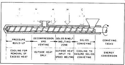
FIG. 13 Basic conveying functions of single-screw extruder and need for
addition and withdrawal of energy. (Werner & Pfleiderer Corporation,
Ramsey, NJ.)
Scale-Up of Melting and Mixing
An extruder is an energy conversion device. In order to maintain a proper energy balance, it is generally necessary to add heat by conduction and to withdraw heat by cooling. The poor heat transfer characteristics of polymer melts are well known; problems associated with heat transfer become more severe with increasing screw channel depth and increased thickness of the polymer layer in the screw channel. The heat transfer area in an extruder increases with the second power of screw diameter, but the volume of material with a given residence time increases with the third power of screw diameter (assuming a constant L/D ratio and comparable screw geometry). Heat transfer scale-up in single-screw extruders becomes increasingly difficult with larger screw diameters; the ratio of inner barrel surface area to volume in twin-screw pilot plant extruders does not differ much from production size units.
Laminar flow patterns in the screw channel of single-screw extruders are disrupted with sufficient statistical frequency by leak-flow over the screw flights leading to changes of shear direction; this is essential for good mixing. As screw diameter increases, the statistical frequency (per volume of material) of shear direction changes decreases, often to a point where adequate mixing cannot be achieved.
Additional shear and mixing devices are used as modifications of basic single-screw concepts (e.g., barrier-type screws, mixing pins, etc.) with good results in operation, but are difficult to scale-up.
Twin-screw extruders provide rearrangement of material layers with every rotation as material is transferred from one screw to the other. The direction of shear relative to the original shear planes can be changed with selection of screw pitch (counter-rotating) or use of staggered screw discs (co-rotating).
Scale-Up of Venting Operations
In removing large quantities of air or volatiles, the problems of foaming and entrainment exist. In the case of removal of volatiles in low concentrations, the problems are primarily caused by very slow diffusion speed of the volatiles in the molten polymer. Residence time, film thickness, and renewal of surfaces become a significant factor in venting. The thickness of the material layer controls diffusion rate; increasing screw channel depths on large-diameter screw extruders makes diffusion-limited scale-up difficult for single- and twin-screw machines. Vent open area and exposed screw surface area are scaled to produce similar vapor velocities in the vent ports.
Scale-Up of Pressure Generation
Screw extruders dissipate energy in generating sufficient pressure to pump molten material through a die. This energy results in temperature rise of the material being pumped. Controlling discharge temperature becomes increasingly difficult with deeper screw flights due to poor heat transfer. The pressure drop for a given die geometry can be calculated, given the rheological behavior of the material. The scale-up task is to predict the temperature rise in screw extruders as a function of pressure.
The "wetted" section of screw used to build up pressure is called the backup length (zone of 100 percent degree of fill). In single-screw extruders, the entire screw is 100 percent filled (except for vent areas); the length of the metering zone with fully molten material is used to determine pressure-generating capability and temperature rise. The backup length in twin-screw extruders might only be a few turns of the screw. Because of improved pumping efficiency, viscous energy dissipation of intermeshing twin-screw extruders is greatly reduced.
Scale-up models can predict temperature rise in generating a specific pressure with a given screw geometry (single- or twin-screw) and rheological properties of the material; backup length (twin-screw) or length of the metering zone (single-screw) necessary to develop this pressure can also be calculated.
Materials of Construction
Screw extruders experience abrasion and/or corrosion depending on the process application; materials of construction for screw and barrels are selected for optimum service life. Most screw extruder components are manufactured from carbon steel and may be nitrided or through-hardened for wear protection. Modular designs of screw elements and barrels have distinct advantages for corrosion and wear protection. New machines only have to be equipped with wear-protected components in the area where wear or corrosion is expected. In a corrosive environment, the generation of a galvanic element by pairing of different materials has to be avoided.
With varying barrel wear along the processing section, barrels can be exchanged and relocated so that all barrels are worn down uniformly to the point where a replacement becomes necessary. The same philosophy applies to screw elements.
Besides adhesive wear, which is experienced in some extruders due to contact between screw and barrel, the following wear mechanisms may be observed:
1. abrasive wear due to the material being processed or fillers contained in the material (e.g., glass-fiber-reinforced thermoplastics, mineral fillers, etc.)
2. corrosion due to aggressive acidic or basic components in the processed material (e.g., fluoropolymers, chemical reactions, etc.)
Designs for Wear-Protected Barrels
Several designs are available for manufacture of barrels for corrosion- and wear- protection. Exchangeable liners provide the most flexible and economic solution.
Liners can be press-fit into barrels or split-barrels designed to bolt around the liner. The space between the liner and split-barrel is usually filled with heat-transfer cement to eliminate air gaps. Barrel liners are typically through-hardened, manufactured from castings, or machined from forgings. High chrome, high carbon alloys provide excellent wear resistance due to a high content of chromium carbides.
Bimetallic liners may also be utilized, with two bimetallic tubes welded together for twin-screw applications. The bimetallic liner has high adhesive wear resistance (NiCrB or NiCrMo alloys with or without carbide reinforcement) with a ductile backing material.
Barrels that do not have liners may have surfaces welded with hard-facing materials and machined to original bore dimensions. Unlined barrels may also be machined to accept a liner.
Corrosion-resistant barrels or liners may be manufactured from hardenable chromium steel or CoMoCr alloys for extremely high corrosion resistance in addition to very good wear resistance.
Designs for Wear-Resistant Screws
Extruder screws are subject to the same corrosive and/or abrasive environment as barrels and are manufactured from material suited to the application. The crests of screw flights can be welded with hardened materials (e.g., stellite), screws can be through hardened (e.g., tool steel), spray-coated (e.g., carbide coatings), or chrome plated; corrosion-resistant materials (e.g., lnconel -type, hardenable stainless steel) are also available.
Extruder manufacturers can provide recommendations for materials of construction based on field experience.
Extruder Maintenance
Routine maintenance of screw extruders can be divided into two sections: gearbox/drive motor and process section. Extruder manufacturers provide recommendations for preventive maintenance intervals based on experience in normal operations; modifications to these intervals will depend on the particular process application.
Gearbox/Drive Motor Maintenance
Scheduled maintenance on the extruder gearbox involves checking lubricating oil level, temperature, and pressure on a regular basis. Lube oil specifications are provided by the extruder manufacturer. Service life of gear oil depends on gearbox loading and environmental factors, but it typically should not exceed 12,000 operating hours or three years. Oil should be inspected every 2,000 operating hours (sample analysis). Radial bearings have an expected lifetime as a function of average screw shaft speed and average load. This information is provided by the extruder manufacturer to schedule radial bearing replacement in the gearbox.
Thrust bearings also have an expected lifetime as a function of average screw shaft speed, average material pressure, and average load. As with the radial bearings, expected lifetimes are calculated for normal operating conditions; operation at low screw shaft speed, low material pressure, or low motor loading increases lifetime.
In all cases, bearing overhaul is typically recommended within 64,000 operating hours.
Shock pulse metering (SPM) or acceleration-spike energy systems are available to monitor extruder bearing conditions, giving early warning of possible failure.
Gearbox overhauls are usually performed on site with or without supervision from the extruder manufacturer, or gearboxes can be returned to the manufacturer for overhaul.
Torque-limiting clutches that are not positive-disengagement-type should be checked if clutch slipping occurs; a clutch will disengage at a different setting as pads or shoes wear (recalibration may be necessary). Maintenance of drive motors is generally performed under recommendations from the motor manufacturer.
Process Section Maintenance
Maintenance of extruder screws and barrels becomes necessary when machine performance deteriorates due to abrasive or corrosive wear; routine inspection of process section components is recommended.
Worn barrels and screws can be reconditioned to factory specifications depending on their condition and material of construction. New crests can be welded on worn screw flights and precision-ground to original dimensions.
Barrel cooling channels may become fouled or have scale deposits that restrict the flow of heating/cooling fluids. Plugged or fouled cooling bores are often repaired by the extruder manufacturer.