AMAZON multi-meters discounts AMAZON oscilloscope discounts
INTERNAL MIXERS
Internal (Banbury-type) mixers have found widespread application in the rubber industry, where high-horsepower mixing is required for masticating and compounding; the technology has been successfully applied to plastics and chemicals for high- and low-viscosity systems:
Rubber Applications |
Plastic Compounds |
Other Applications |
Tires, tubes Molded articles, profiles Hoses, gaskets, seals Shoe soles, heels Foam, sponge rubber Packing, sealing, roofing Flooring (sheet) |
Polyvinylchloride (PVC)s (flexible, semirigid) PVC scrap reclaim ABS (molding) Polyethylene, polypropylene, PVC, ABS color concentrates Phenolic Thermoplastic/rubber blends |
Adhesives, sealants Carbon electrodes Ceramics Chewing gum Dewatering, devolatilizing Pharmaceuticals |
The common goal is to mix solid and/or liquid additives into a rubber or plastic-type matrix. Additives (agglomerated particles or droplets bound by surface tension) must be separated, reduced in size, and uniformly distributed within the matrix: Two types of mixing phenomena are involved: extensive mixing and intensive mixing.
Extensive (also known as distributive) mixing is responsible for spatial distribution of the individual particles within the polymeric matrix. Intensive (also known as dispersive) mixing is responsible for separating and reducing the particle size of the additives.
Principle of Operation
Internal mixers are designed to provide intensive and extensive mixing. Intensive mixing occurs in the narrow gap formed between the rotor tip and the mixing chamber wall. The mixture is repeatedly passed through this high shear field where fluid mechanical stresses separate and rupture agglomerates; dispersive forces are similar to those in a two-roll mill. Extensive mixing takes place between the rotors: the mixture is circulated from side to side and from one end of the mixer to the other after passing through the shear zone.
Energy dissipation from intensive mixing results in heating of the mixture.
This heat is removed through the walls of the mixing chamber, the rotor bodies, and other contact parts (ram, discharge door, etc.) through cooling channels. The effective heat transfer of internal mixers can be the limiting factor to intensive work, since discharge temperatures cannot exceed the critical temperature of the mixture, which is determined, for example, by thermal breakdown of organic phase, onset of undesirable reactions (e.g., cross-linking), or the decrease of continuous-phase viscosity to a point where dispersion cannot proceed. Poor heat transfer will cause these temperature limits to be reached before dispersion is complete.
Design Features of Internal Mixers
Optimum dispersion is achieved through proper selection of machine type and process parameters. Internal mixers are available today with intermeshing and tangential (nonintermeshing) rotors. Rotor design is a critical factor in mixer performance, and some manufacturers offer various rotor configurations. (This topic is covered in detail later). FIG. 1 shows the major components of internal mixers. A completely enclosed mixing chamber houses the spiral-shaped rotors, which rotate in opposite directions and at the same speed (intermeshing design) or at different speeds (tangential design) to keep the material circulating. The gap between the rotor tips and the chamber wall produces intensive shearing of the mixture. A hopper allows for loading ingredients, and an air-operated ram in the feeding neck confines the batch within the mixing chamber. A discharge door allows for quick and efficient unloading of the mixture at the end of the mixing cycle. The mixing chamber, rotors, and discharge door are all temperature controlled with steam and/or water.
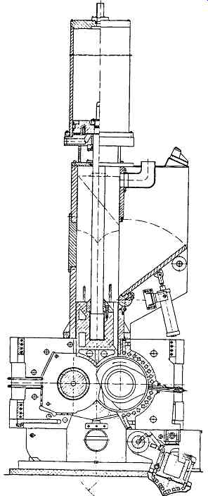
FIG. 1 Cross-sectional view of internal mixer with intermeshing rotors.
(Werner & Pfleiderer Corporation, Ramsey, NJ.)
Mixing Chamber
The mixing chamber body is usually of two-piece construction, split vertically.
This allows for removal on-site without dismantling the entire mixer. The internal body halves are lined with wear-resistant materials to maintain rotor tip-to-wall clearances; the exterior is heavily reinforced for mechanical loading.
Temperature control of the mixing chamber is accomplished with steam or circulating water. The body halves are fitted with one of three types of chamber sides: cored, spray-type, or drilled.
Cored sides have passages arranged in a serpentine pattern running along the length of the sides of the chamber. These passages are usually formed in the casting, through which water or steam is circulated.
Spray-type sides use nozzles to spray water onto the sides for cooling effect; flood-type design is also available, without nozzles.
Drilled sides are the most common type of temperature control for the mixing chamber. Holes are drilled laterally in the body halves and provide a serpentine path for the flow of water. These holes are smaller and greater in number than the cored passages, as well as being closer in proximity to the chamber wall.
End Frames
The ends of the mixing chamber provide support for the mixer body. End frames carry the rotor bearing assemblies and dust-stop seals.
Self-aligning roller beatings are standard on most internal mixers.
Double-acting axial thrust bearings can be used on large internal mixers to increase lifetime and efficiency of the rotor seals.
Dust stops are used to seal dust (carbon black, pigments, etc., used in the mix) within the mixing chamber. There are several designs available; one type relies on a hydraulically actuated yoke to apply pressure on the sealing rings. Self-sealing dust stops use the mechanical pressure of the mixture to maintain seals. Powders or dust that pass into the dust stops are flushed with process oil.
Discharge Doors
The discharge door of internal mixers is designed to provide quick and efficient dumping of the mixture. The door top must be hard-surfaced to withstand the mixing environment; some designs include a removable/replacement door top section. Most discharge doors are provided with passages for heating or cooling media; the door is usually cooled to prevent the mixture from sticking. Two types are available: drop door and sliding door.
The drop door type is pivoted on a shaft running through bearings located in the end frames. The door swings downward (135 degree to 180 degree ) and away from the mixing chamber, providing a clear path for the material discharge.
The sliding door is mounted on an air-operated cylinder. Guides are necessary to provide clearances for door operation. Also available are mixing chambers that tilt over (up to 140 degree) to discharge the mixture through the top opening. Tilting mechanisms are electrically or hydraulically driven.
Feed Hopper
The feeding of materials into an internal mixer can actually take longer than the mixing cycle. Thus, efficient designs are utilized on the hopper assembly of internal mixers to facilitate quick charging of ingredients. The feed opening itself must be large to allow venting of air (and dust) as the batch is charged. The feed opening and throat on larger mixers are sized to accommodate rubber bales intact. Air-operated doors are provided in the hopper assembly to allow for loading of material into the mixer. Openings on the sides or in the rear of the hopper for charging of fillers, accelerators, curatives, and other dry powder components are normally connected to weigh hoppers or other means of feeding.
Ram Cylinder Assembly
A ram is used to confine the batch within the mixing chamber. Air pressure (10 to 120 psi) is applied to the cylinder, forcing the ram down into the mixing chamber.
The bottom of the ram is usually shaped to conform to the gap between the rotors (V-bottom). The ram is fitted with a height indicator, used to gauge the state of the mix. Cavity cooling is used for temperature control of the ram bottom. The ram cylinder assembly is usually air-operated, but it can also be a hydraulic device. Ram pressure can have a significant impact on dispersion quality, and it is sometimes used as an operating parameter.
Drive Train
There are three mixer drive arrangements available: "standard," semi-unidrive, and unidrive. Standard drive trains use reduction gears mounted on the mixer base to drive the rotors; one rotor shaft is longer than the other, functioning as pinion shaft and reduction gear. Semi-unidrive systems use a separate reduction gearbox prior to the rotor shaft. One rotor shaft is longer than the other, carrying the pinion gear. Unidrive systems have speed reduction and dual output shafts within a single gearbox. Rotor shafts of equal length are coupled to the pinion shafts from the gearbox.
Rotor speed directly influences mixing quality, mixing time, and batch temperature. Optimum rotor speeds are chosen to process materials at their highest acceptable temperature within the shortest cycle time. A single-speed drive limits the number of formulations that can be processed optimally. Two-speed motors increase internal mixer flexibility. Several other alternatives are also available:
++constant speed motor with integral (or separate) two-or four-speed gearbox
++variable-speed DC or variable frequency AC motor (ultimate flexibility)
Bed Plate
The bed plate is the base frame that anchors the mixing chamber (and possibly gear-box). It is strengthened to withstand torque transfer and vibration of the rotors, as well as to evenly distribute the load of the mixer onto a foundation.
Auxiliary Systems
Operation of internal mixers requires several dedicated systems.
The tempering system supplies constant-temperature fluid to heat or cool the various mixer components. Steam/water, pressurized water, or heat-transfer oils can be used. Several separate circuits may be needed for efficient operation (e.g., ram and mixing chamber at one temperature, discharge door at another temperature, and rotors at yet a third temperature). The lubricating oil system ensures adequate supply of lube oil to critical components in the drive train, rotor bearings, dust stops, etc.
The process oil injection system injects oil into the mixing chamber. The injection nozzle should be a self-sealing type to prevent fouling from mixture.
The hydraulic or pneumatic system operates discharge door (or tilting mechanism), ram cylinder, feed chute door, etc. It is controlled by means of solenoids.
The temperature sensor, strategically located, indicates batch temperature. It may be located in the feeding ram, in the discharge door, or through the end frames. Sensors should have intimate contact with the mixture to provide accurate readings.
Instrumentation and Controls
The degree of sophistication of internal mixer control systems can vary. They can
1. mix batch until desired temperature is reached
2. mix batch for predetermined time period
3. mix batch until predetermined energy is consumed
4. use various combinations of the above
Efficient operation of internal mixers is attained with automation of the mixing process. Increased productivity and consistency in product quality can be realized with computerized control of the mixing line from batch weighing through downstream processing.
Manual Control. Standard internal mixer control systems provide interlocks and data acquisition for manual operation. Interlocks are installed on ram cylinders, feed hoppers, and discharge doors for operator safety and on drive components for overload protection. Operating data are usually recorded on strip-charts housed in a control panel for production monitoring of discharge temperature, power consumption, and cycle times. Stop/start push buttons are provided for drive motor and auxiliary equipment.
Automated Mixer Control Systems. Application of a process computer system to an internal mixer significantly improves batch quality as well as quality consistency from batch to batch. Flow of raw materials, mixing control, downstream equipment, and production planning can all be integrated into a supervisory computer system.
Optimum mixer control is achieved with logic controls and/or combinations of mixing time, energy input, rotor speed, stock temperature, and chemical reaction parameters. Adaptive process control systems allow the mixing process to follow predefined energy and temperature curves that are stored in memory with each formulation.
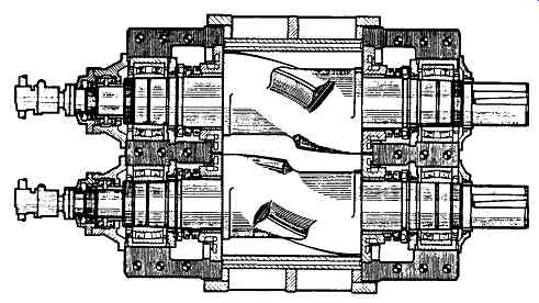
FIG. 2 Plan view of tangential four-wing rotors, rotor bearings, and dust
stops. (Werner & Pfleiderer Corporation, Ramsey, NJ. )
Rotors
Mixing is achieved in internal mixers with the rotors, rotating toward each other at the same speed (intermeshing design) or at different speeds (tangential design). The rotors are designed to interact with each other via the rotor blades, called wings.
Short wings and long wings are used in combination on each rotor. Mixers are available with either two-wing or four-wing rotors. Two-wing rotors have one short and one long wing, while four-wing rotors have two short and two long wings.
The rotors are arranged in the mixer such that the long wing of one rotor interacts with the short wing of the other rotor (FIG. 2). The edge of the blade is called the wing tip, which forms the shearing gap between the rotor blade and the chamber wall.
The rotors are temperature controlled with steam and/or water, which flows through the center of each shaft. Spray-type cooling or forced circulation is available.
Rotors and shafts can be manufactured as a one-piece steel casting or as two pieces: forged steel rotor shafts with rotor bodies shrunk onto the shafts. The entire rotor bodies are hard-surfaced for wear protection or are chrome plated with hard-facing only on the tips.
Rotor Design
Intensive mixing occurs where the material is compressed between the rotor wing tip and the mixing chamber wall. The width of the tip, the clearance between the wing tip and the chamber wall, and the leading/trailing angle affect dispersion. Wing length and helix angle influence the distribute mixing from rotor to rotor and from one end of the mixer to the other.
Tangential Rotors
Conventional internal mixer designs use tangential rotors with two or four wings.
The rotor diameter is equivalent to the center distance between the rotors. Tangential rotor mixers are mainly used for large-volume mixing, as in the tire industry.
Two-wing rotors are characterized by two flow regions due to different radial clearances between the rotors. Mixing intensity is directly influenced by ram pressure with a two-wing rotor system.
Four-wing rotors provide constant radial clearances between the rotors. Total wing length is greater than the two-wing system, producing higher specific energy input and better homogeneity.
The torque capacity of internal mixers supplied with four-wing rotors is approximately 30 percent greater than with the two-wing rotor system. Modified four-wing rotor designs have been developed with enhanced longitudinal (distributive) mixing.
Intermeshing Rotors
Manufacturers of internal mixers have developed intermeshing rotor systems in response to quality and productivity requirements of compounders. The diameter of intermeshing rotors is greater than the center distance between the rotors (FIG. 3). A calendar effect is created by the intermeshing geometry of the wings, resulting in improved dispersion. Intermeshing rotor systems are capable of higher rates of energy input and better heat transfer than tangential designs. The number of mixing steps, as well as mixing time for each step, may be reduced by changing from tangential to intermeshing rotors. Internal mixers with intermeshing rotors are used mainly for high-quality mixing.
Operation of Internal Mixers
Several mixing techniques are commonly practiced using internal mixers: single-stage, master-batch, and multistage mixing.
Single-stage mixing is used for materials that can tolerate relatively long mixing time at low rotor speed; temperature rise is the limiting factor. All ingredients can be charged at the same time or added sequentially while mixing. The sequence of addition of plasticizers and oils is critical to dispersion quality.
Masterbatching is an implied two-stage mixing process. Viscous components and fillers are mixed first. This stage can tolerate higher rotor speed and material temperature. Thus, short mix cycles produce complete dispersion. The batch is discharged and allowed to cool. A fraction of the first stage (masterbatch) is then loaded with the balance of ingredients that make up the total formulation. The predispersed masterbatch mixes efficiently and can produce higher quality dispersions in less total mixing time than a comparable single-stage mixing process.
Multistage mixing can include several masterbatching steps, a remilling stage to disperse the masterbatch, and final mixing.
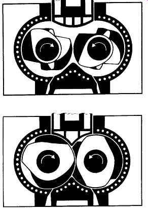
FIG. 3 Tangential (top) and intermeshing (bottom) rotor geometries. (Werner & Pfleiderer
Corporation, Ramsey, NJ.)
Operating Parameters
Optimization of internal mixers requires knowledge of how operational parameters affect mixing quality. Generalized statements can be made as to the influence of fill factor, mixing sequence, ram pressure, rotor speed, mixing time, and temperature control.
Fill factor is an indication of the working volume of the mixer. Chamber volume is used to specify internal mixing capacity (in liters or cubic inches); empty volume is measured with the rotors installed. The working volume is the space occupied by the mixture (function of batch weight, specific gravity). The ratio of working to empty volume gives the fill factor.
Internal mixers are available with chamber volumes up to 650 liters (1), which can handle a 560-kilogram (kg) batch; laboratory-scale internal mixers used for research and development have net volumes as low as 0.41, requiring less than 0.3 kg per batch.
Fill factors vary for different mixer geometries (two-wing versus four-wing; intermeshing versus tangential) and different mixing tasks. Intermeshing rotor mixers generally use lower fill factors than tangential rotor systems, but they can achieve the same level of dispersion in a shorter mixing time. A compound that runs on a tangential mixer at 70 to 75 percent fill factor (four-wing rotor) would run between 60 and 65 percent fill factor on an intermeshing mixer.
Fill factor directly influences dispersion quality, specific energy input, and discharge temperature by providing empty volume for the mixture to circulate within.
Mixing sequence has a significant effect on dispersion quality, specific energy input, and discharge temperature when large amounts of oil are being processed.
Oil or plasticizers are typically added later in the mixing cycle, after fillers have been dispersed.
Ram pressure is used as a process variable to influence the specific energy input and discharge temperature. Tangential rotor mixers are more sensitive to ram pressure than intermeshing rotor mixers. Increased ram pressure can shorten the mixing cycle by compressing the batch within the chamber to intensify mixing.
Discharge temperature can be reduced by decreasing ram pressure.
Rotor speed is used to control the rate of specific energy input. Higher rotor speeds can reduce mixing time by dissipating more energy in a shorter time period.
Rotor speed and ram pressure can be independently varied to achieve a target energy input, dispersion quality, or material temperature. Internal mixers supplied with a variable-speed motor have more flexibility in optimizing rotor speed for a given formulation than a single- or two-speed mixer. Large internal mixers operate at rotor speeds of 10 to 60 RPM; laboratory-scale internal mixers operate at speeds up to 110 RPM or higher.
Mixing time in conjunction with fill factor (batch weight) determines the throughput capacity of the mixer. Decreasing the mixing time (by increasing rotor speed or ram pressure) then increases mixer output. Mixing times vary widely depending on formulation and quality of mix. For example, single-stage mixing of one particular rubber formulation and oil, which takes eight minutes on a tangential mixer, can be processed in only five minutes on an intermeshing mixer. A typical tire formulation running on a tangential rotor system takes about three minutes for the masterbatch stage, three minutes for the remilling stage, and two minutes for final mixing.
Temperature control of mixer components (chamber body, rotors, ram, and discharge door) has several effects: adherence of material to rotors (rotor temperature), discharge temperature (cooling effect through chamber body), and efficiency of discharge (discharge door temperature). The mixer is usually started up hot to prevent slippage, and then cooling is applied when the material is in a fluxed state.
Accurate temperature control of each part of the internal mixer helps maintain batch-to-batch uniformity.
Downstream Equipment
An internal mixer usually discharges directly into some type of shaping/forming equipment or onto conveyors. Downstream equipment is sized to provide a continuous process from the batch mixer; two mixers can also be arranged with alternating discharge.
Mixing Mill
Roll mills are used for cooling and shaping as well as for after-homogenizing and mixing. Cross-linking chemicals that cannot be added in the internal mixer due to temperature limitations in single-stage mixing can be added in the mixing mill.
Mixing mills are built with fixed friction ratios (constant speed on rolls), or variable friction can be achieved with variable-speed control of each roll. Adjustment of the roll gap can be carded out under load with hydraulics.
Extruder
Single-screw extruders are used to produce pellets or sheet from the internal mixer.
Pelletizing extruders are fitted with screens or strainers and die-face pelletizers or underwater pelletizers. Force-feeding devices (screws or rams) can also be installed.
Sheet stock is produced from extruders equipped with a roller-die.
Maintenance of Internal Mixers
Routine maintenance of internal mixers requires attention to the various subsystems responsible for smooth operation (e.g., hydraulic, pneumatic, and temperature-control systems). Mixer manufacturers provide recommendations for preventive maintenance on rotor bearings and seals, lubricating oil changes, gearbox overhauls, etc. High on-stream factors are achieved when maintenance records are kept and factory recommendations are followed.
Major overhauls of internal mixers are required when the product specifications (dispersion quality, discharge temperature, etc.) are no longer acceptable. Abrasive wear on rotors, chamber body, and ram becomes evident in mixer performance: dispersion quality cannot be maintained as clearances increase between rotor tip and chamber wall; discharge temperature increases as a result of increased clearances and subsequent reduction of heat transfer. Manufacturers of internal mixers can provide a field inspection service to periodically document wear. Critical components (rotors, bearings, dust stops, etc.) are usually kept in stock for emergency delivery.
Rebuilding of internal mixers is a service performed by the manufacturers.
Worn rotors and chamber bodies can be rebuilt to factory specifications. New dust-stop parts, door tops, and end frames are installed. Older mixer designs can be converted from cored or spray-type sides to drilled sides, from two-wing rotors to four-wing rotors, from standard gear to unidrive, etc.
SINGLE- AND TWIN-SCREW EXTRUDERS
Screw extruders were designed as continuous mixers for dispersing additives into a molten polymer. Intensive or extensive mixing takes place in the extruder as a function of screw geometry and operating conditions. Mixing time in continuous mixers cannot be arbitrarily chosen as in batch mixers, but is determined by operating conditions, screw geometry, and extruder length (residence time). Evaluation of single- and twin-screw extruder designs for various process tasks requires a basic knowledge of key components: gearbox, drive motor, screw shafts, screws, and barrel (FIG. 4).
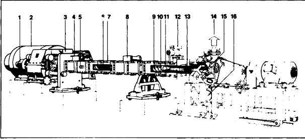
FIG. 4 Extruder components. 1-Thrust bearing assembly; 2-motor with overload
safety clutch; 3- gear box; 4-feed barrel; 5-electrical resistance heater
shells; 6- kneading elements; 7- thermocouple for stock temperature; 8- venting
section; 9- screw elements; 10- stock pressure gauge; 11 - thermocouple for
barrel temperature; 12- start-up valve; 13-screen pack changer; 14-pellet/water
discharge; 15-UG(under-ground pelletizer); 16-water inlet. (Werner & Pfleiderer
Corporation, Ramsey, NJ.)
Mechanical Description
Gearbox
The gearbox performs speed reduction, torque transfer, and thrust loading for the extruder. These functions can be handled separately with individual components or combined in a single unit. Drive motor speed is reduced to operable extruder screw speed in the gearbox. Various gear ratios are available to provide different output speed ranges from standard motor input speeds. Torque is transferred from the drive motor to a single output shaft (single-screw) or must be equally split for dual output shafts (twin-screw). Axial thrust loading (back-pressure) from the screw shaft(s) is taken up by thrust bearings.
Single-screw extruders are able to utilize large thrust bearings. Twin-screw extruders, however, must use alternative methods, since the close proximity of the screw shafts precludes the use of large bearings. Twin-screw extruder gearbox designs are inherently more complex than single-screw designs.
Drive Motor
Small single-screw (<8 in) and twin-screw (<130 mm) extruders use constant-torque variable-speed DC drive motors to provide process flexibility. Extruder systems can also use constant speed AC motors with mechanical variable-speed gearboxes, variable-frequency AC motors, or even hydraulic drives to achieve the same flexibility. Very large extruders are usually equipped with fixed-or two-speed drives, with an auxiliary drive for start up.
Drive motors can be direct-coupled to the gearbox or belt-driven. Mechanical slip clutches, positive disengagement couplings, or shear-pin devices are installed to provide overtorque protection.
Typical installed power for twin-screw extruders is shown in FIG. 5.
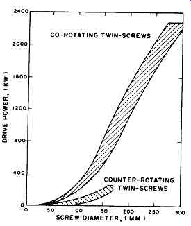
FIG. 5 Installed power for twin-screw extruders. (Werner & Pfleiderer
Corporation, Ramsey, NJ.)
Screw Shafts
The screw shaft(s) transfer the motor torque to the screw(s). Splines, keys, and other methods of torque transfer are used to mount the screws to the shafts. One end of the screw shaft is coupled to the output shaft of the gearbox; on some extruders the screw shaft is an extension of the pinion shaft and is not removable. The screws are fixed to the screw shaft with a screw tip that compresses the screw bushings together on the shaft. Screw shafts can be cored for flow of heat transfer fluids that can enter through the gearbox end or the discharge end.
Extruder Screws
The extruder screw(s) transfer the motor power into the material via viscous dissipation. Single screws are built as one piece or may be assembled from modular sections. Some twin screws are manufactured as one piece, but most are of modular design. The discrete screw elements offer two significant advantages"
1. Process flexibility to alter the screw geometry, thereby influencing shear, mixing, and residence time distribution.
2. As screw elements wear, only those pieces that are subject to abrasion need to be replaced, not the whole screw. Special materials of construction can be used for those particular screw pieces subject to abrasion or corrosion instead of for the entire screw.
Single screws typically have one or two flights; twin screws can have one, two, three, or more flights together on the same shaft ( FIGs. 6 and 7). Screw elements can have various pitch angles, lengths, and number of flights, and can be forward or reverse conveying.
Co-rotating twin-screw extruders additionally use staggered screw discs (called kneading discs, mixing paddles, etc.) to provide additional mixing. The screw discs have various widths and stagger angles, as well as being forward or reverse conveying to tailor the amount and type of mixing required.
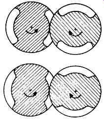
FIG. 6 Cross section of counter-rotating screws. (Werner & Pfleiderer
Corporation, Ramsey, NJ.)
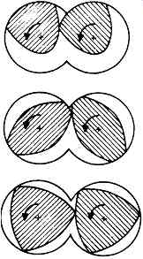
FIG. 7 Cross section of co-rotating screws: single-flight (top), two-flight
(center), three-flight (bottom). (Werner & Pfleiderer Corporation, Ramsey,
NJ.)
Extruder Barrel
As with screws, barrels can be built as one piece or of modular construction. The modular design provides the same advantages as for screws. Barrel sections are open for feeding and venting or closed for conveying and pressure build-up. The extruder barrel can have several openings for venting or feeding solids downstream.
Access ports are provided to inject liquids or for installing melt thermocouples or pressure transducers.
Temperature control of the barrel can be accomplished in several ways: electric heating (with water or air cooling), steam heating, or fluid heating/cooling.
Barrels either have drilled passages or are equipped with external jackets for flow of heating/cooling fluids. Maximum operating temperatures are usually limited by the materials of construction of the extruder barrel, screws, etc. Electric heating is provided with bolt-on resistance or induction heaters. Water or air is used to trim temperature. Several temperature zones can be installed, each with a dedicated controller. Steam heating requires mixing valves to control temperatures or flow control valves to control flow rate. Pressure ratings of barrel jackets or cored passages may limit steam pressure for high-temperature applications. Fluid heating/cooling provides very stable temperature control; commercial heat-transfer oils operate up to 650 degree while glycol solutions may be used for intensive cooling.
Extruder barrels are designed to provide access to the screws for cleaning, maintenance, etc. Clamshell designs are available, which open horizontally (top and bottom) or vertically (side-to-side). In other cases, the screw is pulled from the barrel, or the barrel housing can be pulled, leaving the screw attached to the gearbox.
Barrels can be manufactured with a replaceable liner for wear- or corrosion-resistance. The liners are press-fit or a split-barrel designed to bolt around the liner.
Only those barrel sections where wear or corrosion is anticipated need to be built of special materials or replaced when worn.
Miscellaneous
A feeding device, located near the feed opening of the extruder, is a starting point common to single- and twin-screw extruders. Its purpose is to provide a continuous source of raw materials from a storage bin or mixer/surge system to the extruder.
Volumetric or gravimetric metering equipment is used to regulate throughput with twin-screw extruders; a simple gravity bin with bottom discharge can be used with single-screw extruders, since the extruder operates at 100 percent degree-of-fill in the feed section (flood feeding). Starve-fed extruders are very sensitive to feeding; disturbances or fluctuations may not be dampened out within the extruder. Separate feeding of several components to a twin-screw compounding extruder requires a gravimetric feeding system for accurate metering.
Force-feeding devices are used in conjunction with single- and twin-screw extruders for improved feeding of low-bulk-density materials. These are available in single-or twin-screw configurations for side feeding or vertical feeding (FIG. 8).
Shear control mechanisms are designed to alter the shear intensity of the screw(s) while the machine is running. Several designs are available; most operate on the principle of a variable orifice restricting flow in the screw channels or at the screw tips.
Downstream equipment is used in conjunction with single- and twin-screw extruders to form, pelletize, and filter.
Extrusion dies are available to produce strands, sheet, film, fibers, and profiles.
Heat- and shear-sensitive materials can be processed in a two-stage extrusion process: a second extruder or gear pump is used to pressurize the die, relieving the compounding extruder of this task.
Pelletizing equipment depends largely on the properties of the material. Molten strands can be pulled through a water bath (if the material has enough strength) and fed into a strand cutter. Underwater pelletizers are used if the material tends to smear when cut in air. Water-ring pelletizers and other types of die-face cutting are possible if the material can be cut in air and cooled in an air or water conveying system.
Screens are used to filter molten polymers for film and fiber extrusion. Fixed screens, screen-pack changers, or deep filter elements are installed between the extruder and the die assembly.
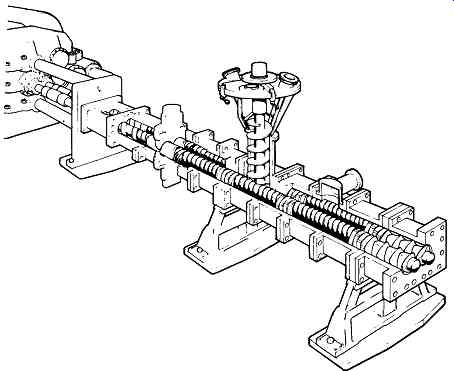
FIG. 8 Downstream feeding of abrasive resin extenders and additives reduces
extruder wear and maintenance costs. (Werner & Pfleiderer Corporation,
Ramsey, NJ.)