AMAZON multi-meters discounts AMAZON oscilloscope discounts
Centrifugal separators are used in a variety of applications, some of them in conventional technology, such as food processing, for instance dairy creamers and chemical conversions. More recently, the design demands placed on this technology have increased with mineral beneficiation applications, such as extracting synthetic crude from oil sands. When the prototypes of this application were first tried in 1977, the centrifuge nozzles had a life of a few hours. The material had to be changed to one that better withstood the highly abrasive sand involved. The nozzle angle also had to be varied.
INTRODUCTION
Frequently, mixtures of solids and liquids must be separated into their components in order to be effectively utilized. The mixtures may be of different solids or the liquid fraction may contain dissolved solids that are to be removed. Such situations occur in food processing, mineral beneficiation and chemical conversions.
When the solids and the density difference is small and the flow volume is large, disk nozzle centrifuges are often the best means to accomplish the purification. The separation which takes place within the rotor of a disk nozzle centrifuge is effected by the G force, the "rising rate" of the liquid (related to the feed flow)
and the separation area provided by a set of conical, close-spaced disks as well as the process factors of fluid viscosity, particle size, shape, and density. In addition, the design of the equipment must allow for the quantity of solids to be handled, the flow characteristics of the slurry and other practical engineering considerations.
Whereas disk nozzle centrifuges have been in use for concentration purposes for a long time, they are now employed as purifiers; in which instance a large flow of "upflowing" liquid greatly enhances the purity of the products.
A benchtop illustration makes it easier to see how this elutriating stream functions. Using this concept we can deduce the beneficial action of displacement washing versus dilution washing and how the improved flow pattern enhances the "classification" of particles. Three examples are presented which show typical processes.
Disk nozzle centrifuges have been used for over 60 years for the concentration of fine solids in a stream of slurry feed. Such centrifuges are now in common use around the world for handling food products, chemicals, minerals, biological materials and waxes. These centrifuges are made in a variety of materials and sizes and in many different countries by various manufacturers with differing design concepts.
However, the significant principles are well established and many publications show the relationships of the operative factors.
In addition to simple sedimentation, where the objectives are to obtain a clarified effluent or thickened solids-loaded fraction or the separation of two liquid phases, it is also possible to simultaneously introduce a stream of "wash" into the centrifuge. There may be several purposes served. First, the discharging solids may exit in the "wash" fluid rather than in the mother liquid, or upflow action of the wash stream may flush out a smaller size solids fraction from the larger size solids fraction. In the first case we have purification by washing (solubles removal) and in the second case we have purification by classification (slower-settling solids removal). FIG. 1 is a photo of an intermediate size disk nozzle centrifuge. This machine is fitted to operate under elevated temperature and pressure conditions and for the purification of terephthalic acid crystals. Note the electric motor, the overhead V-belts and the flexibly mounted beating assembly. These power the pendulum-suspended rotor which has somewhat of a double cone shape, with the nozzles being located at the largest periphery. The housing material is Hastelloy for extra corrosion resistance and the rotor is similarly special to withstand the severe mechanical and chemical conditions.
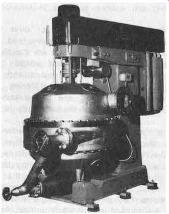
FIG. 1 Shop photo of Merco PCH-30 centrifuge. (Dorr-Oliver Inc, Millford
CT.)
FIG. 2 is a cutaway view of a disk nozzle centrifuge that shows the flow pattern. It is easy to follow the path of the feed slurry as it flows continuously down into a central rotating feed distributor and laterally into the main separating chamber.
Here the high sedimenting force (of perhaps 5000 g) acts to draw the heavier solids outward where they discharge from the rotor through backwardly reacting nozzles.
This slurry is then gathered in a collecting volute and recycles (by means of its velocity head) back to a re-injection port in the bottom of the stationary housing and jets back into the rotor hub where it is re-accelerated.
A major portion of the underflow can be drawn off through a valve located appropriately in the return loop. Meanwhile, the surplus flow (the feed minus the draw-off) moves inwardly through the separating disks, where fine solids are removed, and it discharges from the top of the rotor as clarified overflow. The method of feeding into the disk stack through a set of vertically punched holes and the arrangement of spaces on the disks are well known. They are sized and located in a specific fashion appropriate to the application. Similarly the recycled flow is directed through special tubes back towards the nozzle region.
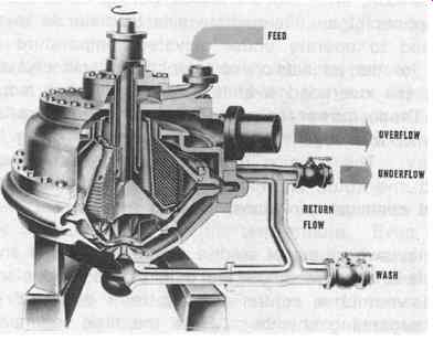
FIG. 2 Cutaway view of a disk nozzle centrifuge and its flows. (Dorr-Oliver
Inc, Millford CT.)
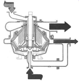
FIG. 3 Cutaway view of Merco centrifuge with a special wash inlet. (Dorr-Oliver
Inc, Millford CT.)
FIG. 3 is a cutaway view of the centrifuge with a special wash inlet system inserted at the bottom of the housing. This system makes it possible to inject large volumes of wash at the interior of the rotor where the flow must travel inwardly and counter-currently to the outward motion of the solids. This action can accomplish a great increase in the washing capability of a single stage or it can significantly enhance the sharpness of the separation between two classes of solids.
In the process of washing, the most important thing is to remove the contaminants as completely as possible. Thus, the use of large quantities of wash are generally of benefit. However, we often want to conserve the wash fluid for economic reasons. Accordingly, a balance is struck and the degree of efficiency of washing becomes important.
In the process of classification, the most important thing is to remove all of the slow settling solids but to not remove the other solids. Thus, the appropriate quantity of wash has to be sought by testing.
DISK NOZZLE CENTRIFUGES
The solid-liquid separation in a disk nozzle centrifuge is involved with the physical properties of the solids and the fluid as well as the fluid dynamic phenomena in the disks. Since the flow pattern inside the rotor is very complicated, much effort has been devoted to the understanding of the separation mechanism and to improving the separation efficiency.
The process of sedimentation of solid particles in a tank can be contemplated in order to understand the mechanism of centrifugal clarification. FIG. 4 shows the continuous clarification of solids in a sedimentation tank. A solids suspension with different particle sizes is fed to the tank and flows out at a velocity w. The suspended solids settle at a velocity v to the bottom of the tank. The processing capacity of the sedimentation tank can be calculated from the terminal velocity of the particles with a critical diameter (dc). The critical diameter is the minimum diameter of the particles that can be completely separated in the sedimentation tank.
Stokes' law predicts the sedimentation velocity (v) of particles under gravity as follows:
d 2 (Ps - Pl ) v = g (eqn.1)
18/.t
...where d is the diameter of the particles; Ps the density of solids in the suspension; Pl the density of the liquid phase; /z the viscosity of the liquid phase; and g the acceleration due to gravity.
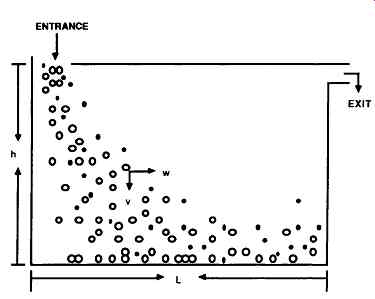
FIG. 4 Continuous clarification of solids in a sedimentation tank. (Dorr-Oliver
Inc, Millford CT.)
By inserting the critical diameter, densities and viscosity in the above equation, we can readily obtain the sedimentation velocity (Vg) of particles with the critical diameter. The retention time of the process stream in the sedimentation tank can then be calculated by dividing the volume of the tank by the flow rate (Q), thus,
... where V = bhl and b is the width of the tank, h the height of the tank and l the length of the tank.
In the same period of time, the particles settle to the bottom of the tank. The longest time that particles take to do this is for particles with the critical diameter, so
... By equating the above two equations, the capacity of the sedimentation tank can be obtained as follows:
... where A is the bottom area of the tank. The above equation shows that the height of the sedimentation tank does not influence the process capacity and that the capacity is linearly proportional to the bottom area of the tank.
Accordingly, more horizontal plates might be inserted into the tank as shown in FIG. 5 in order to increase the capacity of the tank. Thus, the total capacity of the tank is
Q = NAvg
...where N is the number of horizontal plates. With a continuous flow of a slurry stream in the above mentioned tank, the separation path can be easily clogged by the settled particles after some period of operation. If the horizontal plates were inclined at an angle, then the sedimented particles will slide down to the bottom of tank during the sedimentation process. In this case, the area term in equation (5) is the projected area of the inclined plates. FIG. 6 shows the concept.
If the sedimentation tank with inclined plates is transformed into the configuration shown in FIG. 7 to allow the use of centrifugal force to enhance the separation power, we have a prototype of the disk centrifuge.
Within the centrifuge, the traveling distance of the solids is confined in the space between two disks. Usually, rectangular metal bars are placed on the top surface of disks, and their thickness determines the disk spacing. The disk spacing is adjusted according to the solids load and the properties of the process slurry.
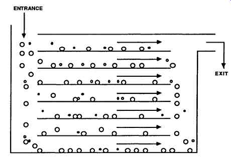
FIG. 5 Sedimentation tank with horizontal plates.
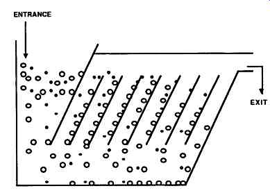
FIG. 6 Sedimentation tank with inclined plates.
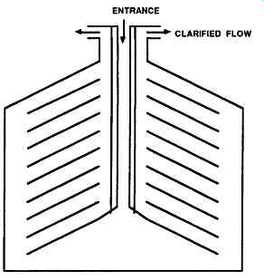
FIG. 7 Prototype of a disk centrifuge.
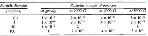
TABLE 1 The Reynolds Numbers of Spheres (SG = 2.8) at Different Accelerating
Forces Particle diameter; Reynolds number of particles
Since the rear surface of disks is critical for solids traveling down away from the separating zone during centrifuging, the surface is manufactured to be as smooth as possible. The metal bars also separate the disks into many sectors in which separation takes place. The segregation by the metal bars also limits the influence of the Coriolis effect which can reduce the separating efficiency to a great extent.
During continuous operation a steady state is usually maintained so that the underflow concentration is held constant, which is very beneficial to the downstream process. In this case, the underflow flowrate should be able to be adjusted so that a desired concentration can be achieved. The discharge from the centrifuge underflow may not always provide the desired concentration so a recycle device is needed.
Dorr-Oliver's Merco centrifuges are equipped with a recycle bend, and this permits more functions for different applications. In addition to clarification and concentration, operations such as washing, classification and soluble recovery can be done with centrifuges with an underflow regulating valve and a return bend.
The motion of a particle in a sedimenting centrifuge may be regarded as strictly analogous to that of a particle settling under gravity, with the difference that the gravitational acceleration is replaced by centrifugal acceleration, w^2r. At a given value of acceleration, a particle will accelerate until it reaches a constant terminal velocity at which the centrifugal force is balanced by an opposing drag force due to the friction between the surface of the particle and the fluid through which the particle is traveling. The terminal velocity subject to a centrifugal force may be expressed as follows.
...where w is the angular velocity of the particle in the settling zone and r is the radius at which settling velocity is determined. The term (w^2r/g) refers to the G force.
In order to justify the validity of Stokes' Law used for settling particles in the centrifugal bowl, the Reynolds number (Re) of the particles has to be evaluated. The much higher accelerating force generated in a centrifuge raises the possibility that a different flow pattern might result. If spherical particles having specific gravity of 2.8 settling in water is taken as an example, the Reynolds number can be calculated for differing sizes of particles under certain gravitational forces. TABLE 1 indicates the results. It provides reasonable confirmation for the general assumption of Stokes' law for usual industrial combinations of particle size and gravity.
Whereas the sedimenting surface area linearly affects the capacity of the sedimentation tank as discussed above, the "Sigma" concept proposed by Ambler has been widely used in centrifugal studies, in which the capacity of the centrifuge is expressed in terms of the equivalent area of a gravity settler performing the same duty. Similar to equation (4), the throughput of a centrifuge can be expressed as follows:
...where V is volume of liquid held in the system and S is the thickness of the liquid layer. Comparison of equations ( 1), (4), ( 6) and (7) shows the following equality:
This is termed the Sigma factor, E, for a given centrifuge, since it is dependent only upon the characteristics of the centrifuge and not upon the solid/liquid system which it is handling. Sigma theory shows that ... if the concept of a 50% cut point is taken into consideration. The 50% cut point is the diameter of particles half of which will be removed in passage through the centrifuge bowl, and half of which will not be removed.
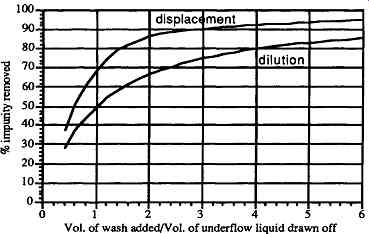
FIG. 8 Advantage of Merco centrifuge washing.
WASHING
Washing processes are commonly employed in the food, chemical and pharmaceutical industries. The main objective of washing is purification, which is to reduce the concentration of soluble materials (impurities) in the mother liquor. There exist two modes of washing, dilution washing and displacement washing. Taking a bath and taking a shower are examples showing the difference between these two modes.
Usually displacement washing gives better efficiency than does dilution washing.
Typical washing efficiency curves for these two washing modes are shown in FIG. 8.
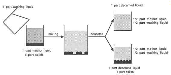
FIG. 9 Dilution washing mode for 50% mother liquid removal.
FIG. 9 shows the conventional system of washing by dilution. In one stage the feed mixture is diluted, and then the insoluble solids settle since their specific gravity is higher than that of the liquid. The soluble impurities in the mixture are reduced by the ratio of the quantity of washing liquor to the quantity of mother liquor. For example, if a ratio of 1:1 is applied, the soluble impurities concentration is reduced by 50%.
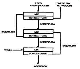
FIG. 10 Countercurrent dilution washing circuit. (Dorr-Oliver Inc)
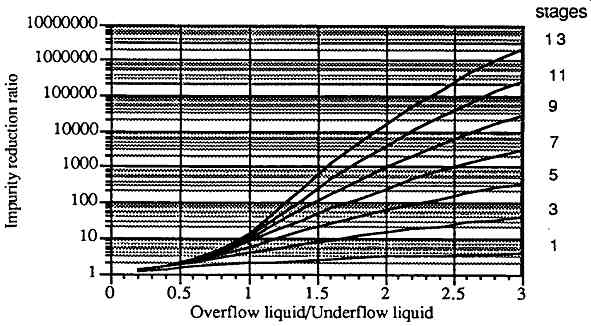
FIG. 11 Impurity reduction ratio by dilution washing mode at various wash
quantities and stages.
In an actual operation, a series of stages may be set up to operate counter-currently. FIG. 10 shows a process in which the process material mixes with the overflow stream from the second stage before going to the first stage. The overflow of the first stage goes back to the process, while the underflow is concentrated in the first stage and fed to a mixing tank to mix with the overflow of the third stage.
The circuit of the streams extends to as many stages as needed in such a pattern.
A governing equation for describing the counter-current dilution washing scheme is as follows:
...where S, is the soluble ratio at stage n and r,, is the wash ratio (overflow rate over underflow rate) at stage n. This equation states that the soluble ratio for any stage is the wash ratio times the solubles ratio for the succeeding stage plus one. Since, in the final stage, the soluble ratio is unity and if the underflow rate is constant, then the soluble reduction ratio in n stages in a series is as follows:
The above equation cannot be used for the case when the wash ratio is one. When the wash ratio is one, the reduction ratio for n stages can be calculated as follows...
FIG. 11 describes the impurity reduction ratio for different numbers of stages at differing wash ratios. The dilution washing mode can be found in processes where such solid-liquid equipment as hydrocyclones, screens and decanters are operated.
===
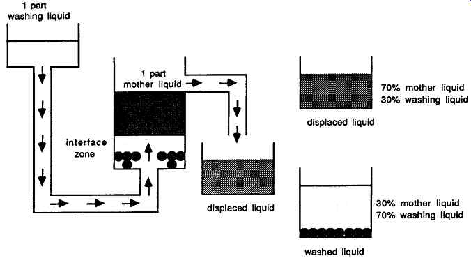
FIG. 12 Mechanism of displacement washing mode.
===
The mechanism of displacement washing is shown in FIG. 12 where the washing liquid enters from below and pushes the mother liquor in the container upward and replaces the mother liquor. In this way the washing efficiency can be greatly increased. Seventy percent efficiency is assumed in FIG. 12 so that the displaced liquid contains 70% mother liquid and 30% washing liquid, whereas the wash liquid with all of the insoluble solids contains 30% mother liquid and 70% washing liquid.
The efficiency depends on the stability of the interface as well as the degree of mixing. When a liquid is displaced by another immiscible fluid of lower viscosity, the interface between the phases is frequently unstable. The phenomenon of "viscous fingering" will result. The degree of mixing is caused by the turbulence in the eddies of the flow patterns.
In the displacement washing mode, the concentrations of overflow and undeflow streams are different. The concentration of soluble impurities in the underflow can be separated into two parts; a certain fraction, R, being from the feed, and the remainder, I-R, from the wash stream. An equation can be derived for the displacement washing mode as follows:
If the underflow rate and wash rate are constant in the series of counter-current washing stages, the values of a and rn being the same for every stage, a general ... equation describing the soluble reduction ratio as a function of displacement ratio (wash rate over underflow rate) is as follows:
When the displacement ratio (W/U) is 1, the above equation cannot be used, instead, the following equation should be employed:
This is a much more effective procedure than dilution washing. In fact, in most cases only one stage need be used but, of course, there are cases where the impurities must be eliminated to such an extent that several stages are employed and these are arranged to be counter-current as shown in FIG. 13. FIG. 14 describes the impurity reduction ratio in a series of stages at different displacement ratios (W/U). From FIGs. 11 and 14, we can easily observe that fewer stages are needed for the displacement washing mode than for dilution washing. For example, to achieve an impurity reduction ratio of 100, four stages are needed for displacement washing at the displacement ratio of 1.5, while nine stages are needed for dilution washing at the wash ratio of 1.5. The displacement washing mode may occur in rotary vacuum drum filters, and in some centrifuges such as the Merco (disk nozzle with return bend) and Mercone centrifuge (screen with wash injection).
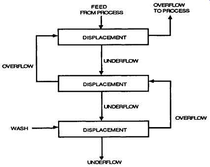
FIG. 13 Counter-current displacement washing circuit.
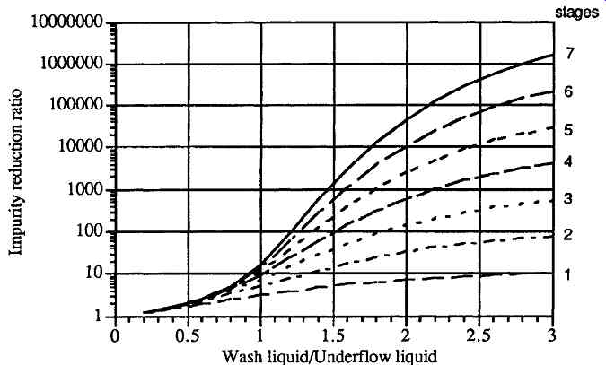
FIG. 14 Impurity reduction ratio by displacement washing mode at various
wash quantities and stages.
Classification
A different aspect of purification involves the removal of solid impurities from a slurry of mixed solids based upon their difference in settling rates. This is called "classification". The solids may be different in nature (protein and starch, for example) or just in size (kaolin clay particles, for example). If two kinds of particles are to be separated and one particle has a specific gravity lower than that of the medium and the other particles have a higher specific gravity than that of the medium, then it is not difficult to separate them, as one would float and the other sink. If both kinds of particles have higher specific gravity than that of the medium, sharp and complete separation of both groups of particles becomes challenging. In this case of classification, the wash stream will be employed and provides another force to be manipulated so that the solids can be classified as desired.
FIG. 15 shows the conventional classification method for the separation of small and large spheres as a time sequence. The large spheres have a diameter two times that of the small spheres. According to Stokes' law as stated in equation (1), the settling velocity of the large spheres is four times that of the small spheres, assuming both have the same specific gravity. At time 0 the mixture is suspended uniformly and then the solids are allowed to settle. The large spheres move downward more quickly. If the mixture is decanted at time interval 2, and the mixture is split into two equal parts, all of the large spheres will be recovered whereas a portion of the small spheres will be present with the large spheres in the underflow stream. If the time interval is increased for example, at time interval 4, more small spheres will settle with the large spheres and make the separation worse.
Thus, the operation of classification following the conventional method will be very touchy and the set-up of the machine specifications becomes tricky.
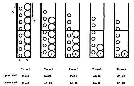
FIG. 15 Principles of the conventional classification method.
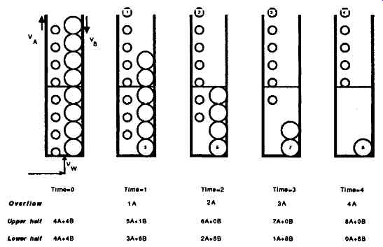
FIG. 16 Principles of the improved classification method.
An improved method is proposed for classification as shown in FIG. 16.
An additional stream is fed as wash and is adjusted to a rate such that the velocity of the wash stream is greater than that of the small spheres and smaller than that of the large spheres. In this case, the velocity of the wash is two times that of the small spheres. Accordingly, the large spheres settle down into the underflow, whereas the small spheres cannot settle down and are carried over to the effluent (overflow). Therefore, sharp and complete separation of spheres can be effected by proper adjustment of the wash flow.
The fine particles in the overflow can be thickened in another centrifuge and the clear liquid fraction can be recycled back to serve as the wash stream. Obviously, the upflow rate of the wash liquid is critical and specific to the situation. If its velocity is too high, all of the spheres may be lost and if the velocity is too low, then some contaminating small spheres may remain with the large spheres. One restriction to this operation is that the size range of the small particles cannot overlap the size range of the large particles. In the overlapping case, a sharp separation cannot be achieved.
Marco centrifuges have washing capabilities which provide a unique feature allowing the operation of classification of particles simply by following the principles illustrated.
APPLICATIONS
Three kinds of processes, i.e. classification of kaolin clay particles, washing of terephthalic acid crystals, and de-waxing of lube oil, are employed for the purpose of discussing the application of the disk nozzle centrifuge in the purification of solids mixtures occurring in the chemical industry.
During the processing of kaolin clay, the raw material is mined and slurried and the coarse sand and grit is removed. Several stages of centrifugation are employed in order to separate the slurry into various fractions for other uses. Such equipment includes decanter centrifuges and batteries of hydrocyclones. High-speed disk nozzle centrifuges are used in several positions in the flowsheet but the most critical station is for "fractionation." The slurry is a mixture of clay solids suspended in water and the solid material is all of the same density and character except for size. The most valuable clay fraction is less than 2 microns but larger than 0.5 microns in size and is used to make paper whiter and improve the appearance of print. Here is where we "cut out" the slimes and leave the bulk of the supply as product. A typical feed would have 30-40% DS and the "underflow" product would be 50-60% DS and the "overflow" product would be 15-20% DS depending upon the product requirement.
The disk nozzle centrifuge would typically operate at high speed and with a large number of large size rotor nozzles so as to cope with the flow requirements. The feed rate to the centrifuge and the underflow compositon (% solids) are controlled by valves so as to render the desired "cut" (the overflow). Operation in this way is quite different than when a centrifuge is in a "clarification" mode. Both fractions are opaquely white and the sharpness of the "cut" requires that the particle size distribution of each fraction be determined. The analyses are done using special instruments.
By using the elutriation wash principle, as described earlier, it is possible to remove the slimes more completely and to simultaneously recover more of the valuable material. The action takes place exactly as explained. The wash is introduced into the centrifuge rotor at the bottom and it enters the slurry bed at the "bottom" (the inboard periphery near the discharge nozzles). The water rises through the suspended bed carrying slimes with it and the flow passes on through the separating disks and discharges as "overflow". Accordingly, the underflow has less slimes remaining in it and the overflow has more. There is some dilution of the overflow due to the additional water.
When this scheme is practiced, a series of runs must first be conducted at various wash water addition rates. The results will show how much benefit each increment of water provides. One can then calculate the optimum combination of feed and wash rates to perform the purification. According to the test results, normal classification by differential settling of kaolin particles gives 75% recovery of the most valued fraction, whereas classification enhanced by elutriating wash results in 85% recovery.
The processing of terephthalic acid affords a rather novel example of the benefit of displacement washing when using a disk nozzle centrifuge. In this case, the product (PTA crystals) is washed while it is suspended in a hot corrosive fluid under elevated pressure and temperature conditions.
Terephthalic acid is made in many countries around the world and by a variety of processes. Some of its uses are fiber, film, and plastic bottles. In most processes centrifuges are employed to separate the solid crystals (less than 200 microns in size) from the mother liquor and a counter-current washing scheme is used to assure the production of purified crystals.
The solids content of the feed may be of the order of 35% DS and the underflow may be exactly the same or at a higher concentration. The large size of the crystals (peaking around 70 microns and none smaller than 20 microns) makes it possible to operate with high upflows of the wash fluid. Most of the Merco centrifuges operate at 10 bar, or less, pressure but some models operate at 20 bar. Higher pressures and temperatures improve the performance by reducing the fluid viscosity.
High-speed disk nozzle centrifuges are used in series where the displacement wash efficiency can be over 90% per stage if high wash ratios are used, such as W/U of 2.2. These particular centrifuges have outstanding performance records for on-stream time and have required very little mechanical maintenance.
A third example involves the processing of petroleum wax which is removed from lube oil by chilling the feed stock together with the introduction of certain solvents which enhance crystal formation. In this process the conventional arrangement is to use rotary vacuum filters in series in order to completely dewax the oil.
The procedure is practiced around the world in similar fashion but on differing flow scales.
Merco disk nozzle centrifuges are uniquely able to perform in this process even though the density difference between the wax crystals and some mixtures of solvents and oil are very small as well as having the handicap of higher-than-normal viscosities. The centrifuges are completely sealed and may be pressurized, as required.
In this example, the percentage of wax crystals is less than in the previous cases and this value will vary with the temperature. Even a small rise in temperature will liquefy some wax--there is no fixed melting point. Both the wax and oil vary according to the source of the crude oil and specific testing has to be done in order to define the performance in each case. Fortunately, this can be done easily. It is also important not to have emissions. This is for environmental pollution reasons as well as the hazard of fire.
In summary, several criteria must be met in order to use a disk nozzle centrifuge for the purification of a solids-liquid slurry, as follows:
1. A continuous supply of a large volume stream of a solids-liquid mixture.
2. An impurity being present that can be separated away by virtue of a differential settling rate to a solids fraction (includes classification and washing).
3. The solids to be small (below 1 micron up to 200 microns) and difficult to settle (otherwise a simple gravity device would suffice).
4. The product to have a substantial value.
5. A complex set of operating conditions can be overcome by virtue of having diverse experience already (corrosion, temperature, pressure, solvents, hazards).
6. High solids concentrations can be reached and high wash rates can be used as well as using multi-stage counter-current systems.
Dilution and displacement are the two washing modes used in process industries. Displacement washing is the more effective of the two, as with substantially less wash, more liquor can be displaced.
Disk nozzle centrifuges with internal recirculation are uniquely equipped for displacement washing, because the wash is introduced into a pre-concentrated underflow slurry, of which most of the mother liquor had been previously displaced within the separation chamber. Using equal amounts of wash versus feed liquor, displacement washing achieves a 70% removal while dilution washing is limited to 50%. Increasing the wash liquor to 2:1 improves the washing efficiency to 90% versus 67% for dilution washing. Washing of starch to remove protein, washing of TPA to remove soluble constituents and the removal of wax fractions from petroleum are just some of the more common and proven applications.
The same principle of upflow used in displacement washing is used for classification purposes to classify very fine from coarse particles. A typical application is in kaolin where 0.5 micron or smaller particles are separated from 2 micron material.
Centrifuges have the added advantage of being totally enclosed, contain a minimum of (process liquid) inventory, operate in a continuous mode, can be easily temperature controlled and are available in corrosion resistant materials.