AMAZON multi-meters discounts AMAZON oscilloscope discounts
Many process operations involve fluid mixing. TABLE 1 lists basic classifications, including liquid-solid mixing, gas-liquid mixing, liquid-liquid mixing, blending of miscible liquids, and fluid motion. In practice, most mixing operations involve several of these.
As shown in TABLE 1, process performance can be judged by physical uniformity, determined by taking samples and calculating the degree of uniformity produced, or by the time it takes to achieve a certain degree of uniformity.
When choosing mixing equipment, the viscosity of the fluids and mixtures is an important consideration, as is the density of materials and the resulting density of the mixture of materials involved. Mechanical mixing equipment can be categorized according to (1) the kinds of impellers used to suit specific process requirements; (2) the types of mechanical drives required to accommodate power, speed, and shaft length; (3)the necessity for sealing the tanks against high pressures imposed by certain processes. Another consideration is the requirement of stabilizing devices on the impellers as well as steady bearings in the tank. However, we will first take a look at some fluid mechanics involved in the mixing tank and some of the parameters that must be measured and observed--the mixers and agitators.
IMPELLER FLUID MECHANICS
A prime consideration is the power drawn by the mixer. In the average plant it is often necessary to measure horsepower, usually by means of electrical measurements for electric motor-driven equipment. Other types of drives are possible; these would include hydraulic motors, air motors, and steam or gas turbines, but electric motors are by far the most common. The most reliable way of measuring mixer power is by means of a recording wattmeter. Clamp-on amp-meters can be used to give an approximation, but they usually must be ratioed to full-load nameplate amperage and may not take into account voltage fluctuations that could exist in plant operation.
When taking a wattmeter reading, the electrical efficiency of the motor must be considered. Alternatively, a motor curve from the motor manufacturer would be helpful in relating amperage readings to the actual output horsepower. Motor manufacturers and mixer suppliers normally have these curves available for different horsepower ratings, different types of enclosures, and varying starting characteristics for motors. The curves would indicate average values expected for particular motor types. If a more accurate reading is desired, an individual motor curve should be considered. Most motors of 100 HP and over have had these electrical characteristics recorded, and motor manufacturers can often produce a motor curve for a particular motor on a given installation.
In any event, a subtraction must now be made for mechanical efficiency in the gear.
Typically, gear reducer efficiencies for spiral bevel or helical gears are about two percent of rated horsepower per reduction. Another subtraction must be made if there is a stuffing box or mechanical seal involved in the equipment. This estimate usually must be obtained from mixer or seal manufacturers. The resulting quantity is the shaft horsepower, and all this horsepower is transformed into heat in the mixing vessel.
It is not recommended that no-load readings be taken as a subtractor for wattmeter average readings. Motor efficiencies are often very low at no-load readings, and these give errors that are too large for accurate calculation of shaft horsepower. All the power produced in the fluid is proportional to the pumping capacity (Q) and impeller velocity head (H). This can be expressed as Pcx QH. However, since the typical mixing system does not incorporate a casing around the impeller, the definite pumping capacity must be through some arbitrarily chosen discharge area of the impeller. Considerable variation exists in practice in this regard, and a particular definition must be obtained when observing pumping capacity data from mixer manufacturers. In addition, the velocity head is not easily measured, so this too is a quantity that cannot be readily related to the shaft horsepower.
In concept, these two quantities are extremely important. The pumping capacity circulates fluid throughout the tank, and the process entrains other fluids with it; so the total flow of the tank may be anywhere from a few percent to as much as ten times higher than the actual flow from the impeller.
The velocity head is related to the fluid shear rate of the system. The fluid shear rate is a velocity gradient and is the only means by which particles get together in the mixing system. If it were not for shear rate, the particles would never meet each other; each one would go around in its own velocity pattern, which is identical to the pattern of every other particle.
Shear rate is an important factor in many processes, and process engineers must carefully consider the shear rate required and make sure that it is compatible with the process result desired.
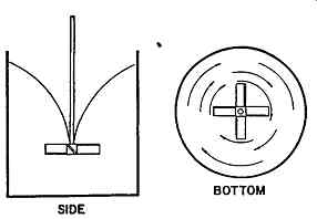
FIG. 1 Typical swirling condition of tank without baffles. (LIGHTNIN Rochester,
NY.)
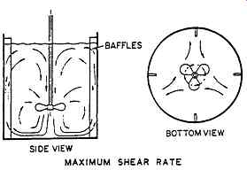
FIG. 2 Typical flow pattern with axial flow impeller tank with wall baffles.
(LIGHTNIN, Rochester, NY.)
When low-viscosity media are mixed in tanks that are unbaffled, they tend to swirl and will produce a vortex, as shown in FIG. 1. Sometimes this action is desirable, but usually it is not. Hence, four wall baffles are often used to produce the flow pattern shown in FIG. 2. These baffles are usually 1/12 of the tank diameter in width. In calculating the strength for supporting the baffles, the mixing tank must resist all be applied by the mixer. Torque is the power divided by the impeller speed or the torque consistent units.
Torque(in_lb ) = HP(63,000) N (RPM)
The baffles must resist this torque, allowing us to divide the torque by the number of baffles, and then by the tank radius to the center of the baffle. This gives the actual torque acting on each of the baffles. Although this torque is distributed over the length and width of the baffle, it is acceptable to assume that the torque operates in equal amounts at the location of the various impellers in the system.
This concentrated load at the midpoint can be used to calculate the baffle thickness and the strength of the support arms required.
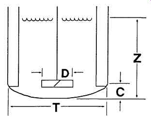
FIG. 3 Nomenclature employed in typical mixer applications. (LIGHTNIN Rochester,
NY.)
Tank Shape
FIG. 3 depicts the nomenclature used in explaining mixer layout and design.
Most tanks are cylindrical and typically have a liquid height over tank diameter (Z/T) ratio of about 1.0. On occasion, tanks have very low Z/T ratios of 0.2 to 0.4, which is typical of the large storage tanks in the petroleum industry. On the other hand, tanks can be very tall and slender. Multiple impellers must be used on large, tall tanks, while single impellers are used on tanks with Z/T ratios of less than approximately 0.8. While the least power is usually required for tanks that have a Z/T ratio of 0.6, the specifying engineer must investigate some additional parameters in an effort to optimize the entire installation. He or she should be aware that tanks with a Z/T ratio of 0.6 are more costly to build than tanks having a Z/T ratio of 1.0, and this may offset the power savings.
Square tanks are often used, as are rectangular tanks. Up to a power level of about 1 HP/1000 gallons, these tanks are self-baffling and do not require additional baffles. Above that level, baffles are required, as shown in the drawing. Four baffles are typically used in square tanks and two baffles in rectangular tanks. There are also tanks with very complicated shapes, including elliptical heads, spherical heads, spherical tanks, and horizontal cylindrical tanks.
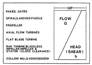
FIG. 4 Chart showing difference between flow and shear. (LIGHTNIN Rochester,
NY )
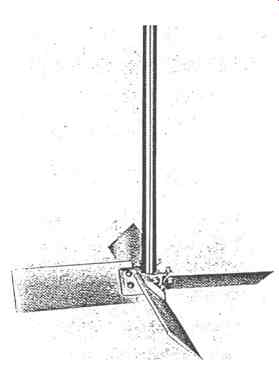
FIG. 5 Typical axial flow turbine. (LIGHTNIN Rochester, NY.)
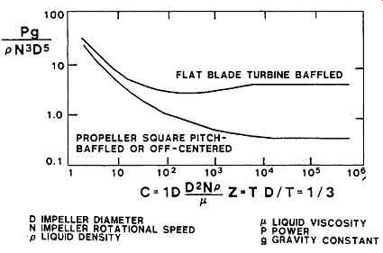
FIG. 6 Reynolds number-power number curve for two different impeller types,
radial low and axial flow. (LIGHTNIN, Rochester, NY.)
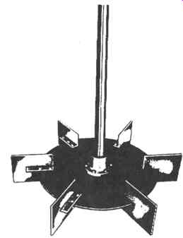
FIG. 7 Typical flat blade turbine. (LIGHTNIN, Rochester, NY.)
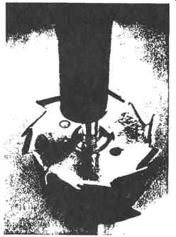
FIG. 8 Typical high-speed disc-type radial flow high-shear impeller. (LIGHTNIN,
Rochester, NY. )
Impellers
There are two basic kinds of impellers, radial flow and axial flow. FIG. 4 shows a spectrum of flow and shear rates for different impeller types. It will be noted that axial flow impellers are typically high-flow, low-shear devices, compared with the radial flow impellers. The axial flow device shown in FIG. 5 has historically been the most common impeller used for axial flow situations. Axial flow impellers incorporate blade angles of about 45 degree to the horizontal, although this angle can vary between 5 degree and 60 degree An impeller diameter over tank diameter (D/T) ratio of 0.3 to 0.5 is quite common, and these ratios are particularly applied to areas where high flow is needed, such as blending and solids suspension.
All impellers have a Reynolds number power curve, as shown in FIG. 6.
This allows the calculation of the Reynolds number when viscosity is known, the Reynolds number being the product of the impeller speed, the impeller diameter squared, and fluid density divided by the fluid viscosity. This has to be in consistent units. Having established the Reynolds number, FIG. 6 can be used to obtain the power number, which is the power times g divided by density, speed cubed, and diameter to the fifth power. From this, the power can be calculated. These curves must be available for the particular geometry of the impeller, baffles and tank configuration.
The fiat portion of the curve depicts the turbulent region, which is commonly for low-viscosity materials. There is also a viscous region in which the slope is minus 1, with a transition area in between.
Radial flow turbines are normally used where higher shear rates are required and where lower pumping capacity is needed. Radial flow turbines include the flat-blade turbine shown in FIG. 7 and high-speed disc turbines for high-speed applications (FIG. 8). An axial flow airfoil impeller (FIG. 9) has higher pumping capacity and lower shear rates than does the axial flow turbine and is particularly suited to blending and solids suspension. It is also particularly suited for large tanks, where often very poor blending conditions exist compared with flow patterns in small tanks in the pilot plant. Axial flow airfoils are not particularly desirable for pilot plant operation, since blend times can appear to be adequate whereas full-scale counterparts may not be. For viscous materials, normally with Reynolds numbers of less than 10, the helical impellers shown in Figure 10 and anchor impellers (Figure 11) are typical. Both are very effective in providing visual blending throughout large-scale systems in viscous fluids and typically operate at speeds as low as 5 to 15 RPM. This is considerably lower than the speed of radial mixing impellers.
During the 1980s highly flow efficient impellers (FIG. 10) were originally designed to maximize the outlet flow in terms of pumping capacity and axial flow direction. This was done to optimize their performance capability in processes such as low viscosity blending and solids suspension. Now there is a whole family of high efficiency impellers" one for gas-liquid applications, another for the paper stock industry, and a third for draft tube circulators.
Recently, additional advances have been made in fluid-foil impellers to extend the range of these impellers beyond the turbulent fluid regime to higher viscosities. Measurements of fluid velocities performed using a dual channel laser doppler velocimeter (LDV) and blending studies have demonstrated equal blend times at one-half of the power consumption compared to a pitched-blade turbine which has historically been used in these flow regimes. The results show that this axial impeller can be effectively used in the transitional flow regimes.
A structural composite mixer with hydrodynamic design and proplet tips (FIG. 11) represents another dramatic change in fluid mixing technology. This vinyl ester resin axial impeller reinforced with graphite and glass fibers, is highly resistant to corrosives and abrasion. Its lightweight composition makes possible the use of longer shafts and increases its effectiveness in deep tank applications.
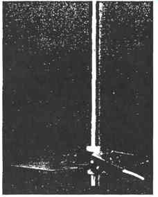
FIG. 9 Typical fluid foil impeller used to provide maximum flow and minimum
shear rates. (LIGHTNIN, Rochester, NY.)
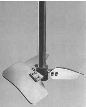
FIG. 10 A320 high flow efficiency impeller with laser doppler velocimeter
measurements. (LIGHTNIN, Rochester, NY. )
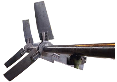
FIG. 11 Fluid foil impeller made from structural composite materials; also
shown are laser measurements of flow characteristics.
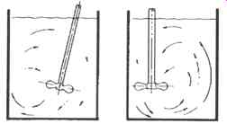
FIG. 12 Illustration of proper angle to achieve top-to-bottom turnover without
wall baffles with portable mixers. (LIGHTNIN, Rochester, NY.)
Portable Mixers
Portable mixers are often provided with suitable clamping devices that permit mounting to the side of an open tank. Portable mixers range in horsepower up to about 3. Constant speed versions are usually either direct driven at 1150, 1450, or 1750 RPM or operate at either 280 or 350 RPM with a gear drive. The gear-driven portable mixer has a larger impeller and operates at slower speed that its direct-driven counterpart. It therefore develops more flow and less shear rate than the comparable direct-drive unit, which has a smaller impeller and higher speed.
Using a ball and socket joint for a clamp allows the impeller to be skewed, as shown in FIG. 13. Good flow patterns can thus be obtained without using baffles. These mixers can also be provided with a permanent angular mounting for open tanks. Portable mixers typically use the airfoil impeller (FIG. 9), although other impellers may be used if called for by special fluid conditions. The gear-driven portable mixer can be more expensive, since it requires a gear drive; this follows the general principle that mixers for low speed and high flow normally require higher capital outlays than mixers producing high shear and low flow. There are many other options available, such as hydraulic motors, air motors, and various kinds of variable-speed motors. Variable frequency, adjustable speed drive mechanisms represent another important option.
Heavy-Duty, Top-Entering Mixers
Industrial fluid mixers for large tanks usually incorporate a two- or three-stage gear speed reduction mechanism. These mixers go up from 2 HP to several thousand HP. The torque provided by the gear box can reach one million in-lb. These mixers are normally installed on the tank centerline. Wall baffles are typically used, and impellers may be either radial flow turbine, axial turbine, or airfoil type. Most gear drives are rated at constant torque. FIG. 13 illustrates the typical range of gear boxes; it indicates that for any given size, the mixer output is proportional to the output speed. Also shown on this curve is a typical process curve for a blending or solids suspension process. This confirms that for flow-controlled applications, there is a trade-off between operating costs and capital expenditures. For example, the choice of mixers can be between a 75-HP mixer, size five casing, or a 190-HP mixer, size four casing, which would cost less in capital dollars but would require more power. For high levels of power and high fluid shear rates, the radial flow flat blade turbine offers good mechanical stability. It has the ability to improve almost any power level that is required for the process.
The axial flow turbine, since it has a higher pumping capacity, is limited to lower power levels. These usually range from 0.5 to 5 HP/1000 gallons. Axial flow turbines are used in applications where circulating capacity is needed with a moderate amount of fluid shear rates. When the only process requirement is pumping capacity and minimum horsepower is needed, the airfoil impellers use power levels on the order of 0.1 and 2 HP/1000 gallons and are very adaptable to blending in solids suspension applications.
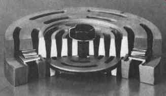
FIG. 13 Typical chart showing power versus output speed for various sizes
of speed reducers. Most speed reducers are rated essentially at constant
torque. (LIGHTNIN, Rochester, NY. )
Typical D/T ratios for all three impeller types are usually between 0.3 and 0.5. When the D/T ratio gets much beyond 0.5, there is a tendency for additional entrainment of fluid to become very minimal. The advantage of large-diameter, slow-speed units is to give more total pumping capacity is not realized.
One of the key design elements of top-entering mixers is that they must run below the first natural frequency of the mixer shaft. In designing a mixer of this type, the operating speed is selected for the particular diameter and power level desired for the process result. The operating speed is divided by the ratio of operating speed and critical speed desired, which most manufacturers set somewhere in the range of 0.7 to 0.8. The critical speed of the shaft can then be calculated.
The radius of the forces acting on the impeller must be calculated from the fluid mechanics and the fluid forces involved in these systems along with a suitable stress level for the material being used. The shaft diameter required at the maximum bending moment point is calculated. In addition, the diameter of the shaft is calculated based on torque requirements. The largest of these three diameters is the shaft required to satisfy all foreseeable conditions. As a general rule, there is some shaft diameter that will allow any length of the shaft to be run overhung with no steady bearing, operating at a suitable distance from the natural critical frequency. Using a steady bearing at the bottom of the tank allows the shaft diameter to be reduced.
The cost of maintenance of the steady beating must be balanced against the extra cost of a large diameter shaft without a steady beating.
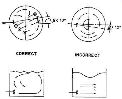
FIG. 14 Illustration of correct flow patterns for installation of side-entering
mixers and large petroleum storage tanks. (LIGHTNIN, Rochester, NY )
Light-Duty, Top-Entering Mixers
There is a gap between the range where typical portable applications stop and where the heavy-duty mixers described earlier must be used. This undefined range is usually in the vicinity of 5 to 15 HP with speeds on the order of 68 to 125 RPM. A variety of mixers are available in this area, all of which have somewhat differing basic design characteristics and which yield satisfactory performance at reasonable cost.
Side-Entering Mixers
Side-entering mixers must be properly positioned in the tank (FIG. 14). Positioning about 10 degree off the tank diameter gives effective flow patterns for many types of blending applications. These mixers are quite commonly used in paper-stock suspension blending, or in gasoline and crude oil tanks, as well as to prevent settling of solids in the sediment and water component of many oil pipelines. Side-entering mixers often produce quiescent zones 90 degree from the entry location. These zones can cause difficulty with solids settling if caution is not exercised in the process design. The major advantage of side-entering mixers is the low initial cost compared with that of top-entering mixers. Top-entering mixers must have a support structure, which adds considerably to the total cost of the installation.
Side-entering mixers will always require higher horsepower for the same application, since they run at higher speeds, typically 150 to 400 RPM. They have smaller diameter impellers than corresponding top-entering mixers and thus require more horsepower for the required circulating capacity. A relativity short shaft and cost savings on the gear box favor the economic evaluation. However, since the mixer shaft must penetrate the tank wall, a mechanical seal is needed. Materials that are very abrasive or corrosive can cause severe problems unless component configurations and materials of construction are carefully chosen and properly engineered.
Bottom-Entering Mixers
Bottom-entering mixers, as shown in FIG. 15, are not as frequently used as top-entering mixers. They are chosen for certain reasons - one of them may be the desire to eliminate the shaft passing through the liquid surface, thus being subject to fouling due to collection of process material on the shaft. While it may be desirable to perform drive maintenance at floor level rather than on an elevated structure, it must be recognized that bottom-entering mixers require a mechanical seal at the bottom of the tank. Seal failure can cause the tank contents to discharge.
Bottom-entering mixers allow the head space to be used for other types of piping connections. One disadvantage is that the high Z/T ratio is not readily handled, since the second and third impellers above the lower impeller are positioned on a shaft that is unsupported and may complicate the design.
Shaft Sealing Devices
There are two types of shaft sealing devices for mixers and agitators. One is the somewhat unsophisticated stuffing box that utilizes soft packing pressed against the shaft by an adjustable gland plate (FIG. 16), upper half). The other sealing method employs mechanical face seals, as illustrated in the lower half of FIG. 16.
Mechanical face seals are an indispensable component of high-pressure, toxic, flammable, or high-value mixer applications. Unlike soft packing, which must be adjusted so as to allow a small amount of leakage in order to provide a lubricating fluid film between shaft and packing, mechanical face seals can be arranged for virtually zero leakage. Moreover, mechanical seal housings can be designed to include stabilizing beatings ( FIGs. 17 and 18) or emergency shutdown features (FIG. 19). FIGs. 17 and 18 illustrate double mechanical seals, which are typically surrounded by a buffer fluid that is maintained at about 10 to 25 psi over tank pressure. Should seal leakage occur, the buffer fluid captured between the two seals would either leak into the tank or toward the atmospheric (bearing housing) side.
However, leakage rates are either extremely small and will be replenished from a makeup container, or else loss of buffer fluid can be detected by appropriate instrumentation and a safe shutdown be initiated without delay.
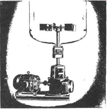
FIG. 15 Bottom-entering mixer. (LIGHTNIN, Rochester, N.Y.)
FIG. 16 Shaft sealing area for mixer-agitators. Soft-packing is shown above
the centerline of shaft; a double mechanical seal is shown below the shaft
centerline for comparison. LIGHTNIN Co., Inc., Rochester, N.Y.)
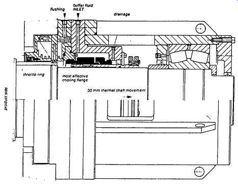
FIG. 17 Double mechanical seal for a modern mixer. (Burgmann Seals America,
Houston, TX.)
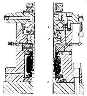
FIG. 18 Double mechanical seal for vertical mixer. Radial and thrust bearings
are incorporated in the seal housing. (Burgmann Seals America, Houston, TX.)
===
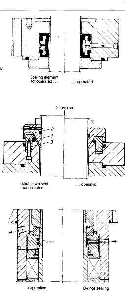
FIG. 19 Shutdown or emergency seals for mixers and agitators. (Burgmann
Seals America, Houston, TX.)
STD
Shut-down seal
Product side shut-down seal with rubber elastic sealing element (item 1), pneumatically or hydraulically operated.
Seal can be changed with the tank filled Suitable for top and bottom drive.
Flange with connection dimensions to DIN 2813 can be supplied.
Shut-down Seal with shaft centering
Product side shut-down seal for agitator with bottom drive.
Seal can be changed with the tank filled.
Item Ir
1 O-ring 2 centering cone 3 thrust ring Emergency Seal
Emergency sealing of the atmospheric side of an agitator seal is possible by pneumatic or hydraulic operated O-rings (item 1). With this version a seat cannot be changed during operation, but aggressive products are prevented from escaping to atmosphere if the seal fails. In order to change the seal the agitator must be stopped.
===
FIG. 19 shows three of many shutdown or emergency seals for mixers and agitators. Upon loss of a main seal, the mixer will be automatically shut down and the emergency seal activated to contain the product in a safe fashion.
It is almost always a serious mistake to purchase the least expensive seal for a mixer or agitator application, as the resulting frequent seal failures will burden the user with high maintenance expenses. On the other hand, properly designed mechanical seals have extended the run time of modern mixers by orders of magnitude. The downtime and repair cost avoidance achieved with superior mechanical seals will often pay for the seals in the first few weeks of operation.
Also see: fluidmixers web-site