AMAZON multi-meters discounts AMAZON oscilloscope discounts
Section A
Water-Flooded Single Screw Process Compressor Technology
The origin of single screw process compressor technology lies in two diverse fields--naval shipboard air compression applications and natural gas applications. It is the naval shipboard air application which fostered the water flooded single screw technology. The combination of water injection and water lubricated bearings has made possible totally oil free gas compression.
Since 1992, significant opportunities for the application of this technology have been recognized in the process gas market.
Certain gas compression applications exist in which oil contamination of the gas is unacceptable. Many of these applications also require that compressor components exhibit a high degree of corrosion resistance. These technological challenges have been met with the development of a family of water flooded single screw process compressors manufactured entirely from austenitic stainless steel. Other materials are available which can be applied to a wide range of operating environments, from relatively inert to highly corrosive.
In concert, the inherent flexibility of the single screw compressor design, the range of materials of construction and the prospect of totally oil free gas compression provides an opportunity to pursue new applications in the process gas market. This compressor class represents an improvement in the technology available to the markets served.
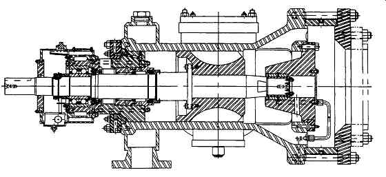
Fig. A-1 Single screw process compressor - driveline section. (Dresser-Rand,
Olesn, NY.)
THEORY OF OPERATION
The single screw process compressor is a positive displacement, high speed, clearance critical, rotary machine.
There have been four different variations of the single screw machine. The "PP" design utilizes a planar screw and planar gate-rotors. The compression grooves are located on the front and back faces of the main screw. Two gate-rotors are used for each side (4 in all) and the shafts for these gate-rotors are all parallel each other.
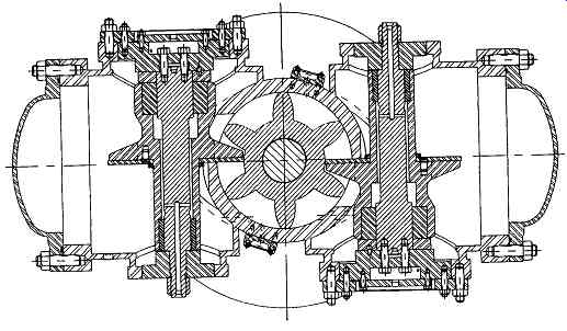
Fig. A-2 Single screw process compressor - gate-rotor section. (Dresser-Rand,
Olean, NY.)
The "PC" design has a similar planar main screw but utilizes 2 cylindrical gate-rotors. Compression occurs on the front face of the screw. The gate-rotor shafts are oriented at opposing angles from the axial face of the main screw. The third design "CC" has both cylindrical gate-rotors and a cylindrical screw.
Compression from the two gate-rotors occurs on the top and bottom face of the main screw. As with the "PC" design, the gate-rotor shafts are oriented at opposing angles. The final design, and the one discussed in this appendix and referred to as the single screw process compressor, is the "CP" design. This compressor has a cylindrical main screw which meshes with two planar gate-rotors ( FIG. A-1 and 2). The gate-rotor shafts are parallel to each other with axes perpendicular to the axis of the main screw. Compression occurs in the volume created when the gate-rotors mesh with the main screw. This volume, along with tight screw to housing clearances, forms a compression chamber. The cycle begins as suction gas is drawn through the front of the compressor and fills the exposed grooves of the main screw ( FIG. A- 3). As the screw rotates, the gas becomes trapped within the three sides of the screw, the cylindrical casing and the gate-rotor. Further rotation causes the groove volume to diminish which increases the internal gas pressure. Near the end of the compression cycle, a machined port in the housing is exposed and the gas is discharged into a plenum. As the groove discharges on one side of the gate-rotor, the same groove is filled with suction gas on the opposite side and the process is repeated. By means of a viscoseal on the high pressure end of the screw and equalization holes in the housing, the main screw is subjected to suction pressure on both ends. Since the front and rear faces of the main screw are nearly equal in surface area, axial thrust loading is substantially reduced. In the absence of this thrust load, Llo life for the main drive bearings increases dramatically. This feature extends the continuous running life of the compressor and enhances its overall reliability.
During the compression process, water is injected into the compression groove. Water enters the compression groove through fixed port holes drilled into the housing. The water acts as a sealant to increase efficiency and a coolant to remove the heat of compression. The injected water is directed through the discharge port with the gas mixture.
A liquid separator is used to remove the gas from the water.
The compressed saturated gas is delivered to the customer's process line while the separated water is cooled, filtered, and recycled through the compressor again. This closed-loop injection water system is typical for all compressor sizes. The injection water system not only supplies both sides of the main screw but also lubricates the compressor bearings.
DESIGN CONSIDERATIONS
Gate-Rotor Support Loading
The planar gate-rotor rides on the horizontal face of a gate-rotor support. This gate-rotor support rotates about a stationary shaft. The gate-rotor support is subjected to load fluctuations throughout the load cycle. For example, at any time, suction pressure may be acting on one gate-rotor tooth, an intermediate pressure may be acting on an adjacent tooth, and discharge pressure can be acting on its adjacent tooth. This combined loading must be supported by the gate-rotor bearings. A computer program has been developed to determine this combined loading. The program first determines the relevant geometric properties of the screw, including volumes and areas at each rotational step.
Once this information is stored, the program determines the pressure-volume profile of the compression process.
Leakage and water injection effects are incorporated into the model. Next, the program determines the number of teeth exposed to the gas at any given time during the compression.
Then the pressures stored for that time are multiplied by the exposed area for the tooth. These forces are totaled for the load step and the program continues. Once the cycle is complete, a diagram depicting the loads is generated ( FIG. A-4). With this information, loading on the gate-rotor support can be determined. The average load is converted into radial and thrust loads acting on the bearings (FIG. A-5). For the single screw process compressor, two fixed profile bearings are used to support the gate-rotor support as it rotates about the stationary gate-rotor shaft. The top bearing is referred to as the free end bearing while the bottom bearing is the thrust bearing.
Water Lubrication
The gate-rotor bearings are lubricated by the system's closed loop water. Using water as a lubricant has a number of benefits. A costly sealing mechanism is not required to seal the injectant from the lubricant. The bearings have relatively cool running temperatures due to the high specific heat capacity of water. However, water lubrication presents a number of design challenges also. The two most significant are the low viscosity of water and its relatively poor properties in the boundary lubrication regime. 1 Laboratory tests have been performed to determine the optimal combination of bearing and journal materials that can withstand the water environment. The single screw process compressor utilizes a hardened stainless steel journal with a graphite grade bearing material. This material has proven to be resistant to the localized water surface velocities and soft enough to interact as a mating surface for the journal. Alternate grades of material have been evaluated in terms of corrosion resistance and could be used if the conditions of the application warranted.
From a design point of view, standard design calculations are used for water lubricated journal bearings. It is important to note however, that the bearing lubricant is the same water used in the process. Therefore, it is imperative to fully determine the fluid and thermodynamic properties of the gas-liquid solution. Once this is known, standard design practice 2.3 can be followed.
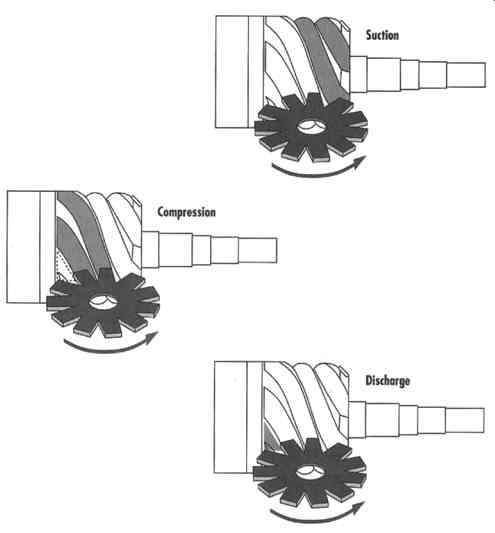
Fig. A-3 Single screw compressor compression cycle - CP design. (Dresser-Rand,
Olean, NY.)
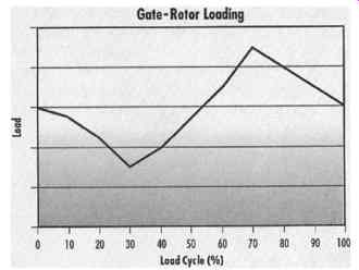
Fig. A-4 Typical gate-rotor loading. (Dresser-Rand, Olean, NY.) Fig. 15A-5
Gate-rotor loadlng. (Dresser-Rand, Olean, NY.)
Sealing
The single screw process compressor utilizes a number of different sealing mechanisms to improve efficiency and prevent process gas leakage to the environment. Three primary seals are employed; the first one located on the high-pressure end of the main screw and the other two located behind the screw on the drive shaft. Seals are not required fsor the gate-rotor supports or the suction end of the screw.
The first seal is a spiral groove seal, or viscoseal. The primary function of the viscoseal is to increase efficiency by reducing circumferential and axial leakage from the compression grooves. Thus it is located on the high-pressure end of the main screw. Very often, this seal is confused with a labyrinth seal. In operation, these two types of seals are very different.
The labyrinth seal is a widely used non-contacting shaft seal. Labyrinth seals are based on positive, finite running clearances which are sufficiently large to preclude the possibility of contact between the seal and shaft. This type of seal is effective by reason of generation of eddies within the cavities created by the grooves. This results in a highly turbulent flow path and inefficient flow process which produces low leakage. Similar to a labyrinth seal, the viscoseal relies on tight running clearances, but it does not depend upon pressure drops across its grooves. A viscoseal is a dynamic seal and is comprised of continuous helical groove cut at a prescribed pitch. Relative motion between the main screw, on which the viscoseal is machined, and the housing induces viscous, or Couette drag, flow in the helical grooves of the seal. 4 A viscoseal can have three possible operating modes; (a) a zero-leakage seal, (b) a leaking seal and (c) a pumping seal.
A zero-leakage seal is classified as having sufficient pumping action to retard the forcing flow. This does not, however, indicate 100% sealing. Liquid droplets will leak from the seal due to instabilities at the interface of the two opposing flows.
A leaking seal is classified as a seal which can not overcome the forcing flow. This may be due to excessive clearances or a relatively short seal length. The last type is a pumping seal. This seal occurs when the pumping action caused by the viscoseal is much greater than the forcing flow. It is in this case where reverse flow may occur. Due to the high reliability of the mechanical face seal located directly behind the viscoseal, the single screw process compressor utilizes a minimum flow leaking viscoseal.
There are many methods available to model the behavior of a viscoseal. Typically, the designer will need to determine the magnitude of the two opposing flows based on the physical dimensions of the seal and housing. For the forcing flow, or the liquid that is being sealed, bushing-flow equations can be used:
To model the drag flow induced by the viscoseal;
As evidenced by the equations, viscoseal flow is highly dependent on the geometry of the seal. Other factors such as eccentricity, Reynold's number and rotative speed are considered during the design of the seal. An effective viscoseal is determined when the two equations are equal. 4 The next seal within the single screw process compressor is a mechanical face seal on the main shaft behind the screw. The purpose of this seal is to prevent gas and/or fluid leakage from migrating along the shaft and into the environment.
The seal utilizes two mating surfaces that form a tight seal during operation. As with the bearings, a significant amount of research went into material compatibility issues. A typical seal will have one relatively soft surface riding on a substantially harder material. For the single screw process compressor lineup, both materials are impervious to corrosive gases and process fluids.
The third line of defense is a vent/purge cavity to which the customer can attach a line to safely remove and leaking gas from the cavity or purge the seal cavity with an inert gas.
This cavity will come into play if there is a failure of one of the previous seals. Finally, directly behind the vent/purge cavity is one additional seal. This seal protects the bearings from becoming contaminated with any leaking gas. For most processes in which this compressor may be applied, it is imperative the process fluid and/or gas does not enter the oil flooded drive bearings.
Discharge Temperatures
An appealing feature of single screw compressors is the ability to compress large ratios in a single stage. Typical applications range from 2-16 ratios, yet higher ratios are achievable. The liquid injection in the compression process enhances the machines ability to reach these pressure ratios.
For a reciprocating compressor, the discharge temperature is dependent upon a number of different factors; i.e. lubrication, friction, valve losses, piston leakage, suction preheat and cylinder cooling. However, a theoretical temperature can be estimated using the isentropic relationship:
Using this estimator, reciprocating compressors reach fairly high (>149~ discharge temperatures after 3.5-4.0 pressure ratios. This heat has detrimental effects on compressor efficiency, as well as, negatively affecting the overall life of the compressor components.
The discharge temperature for a single screw is determined differently. Since water is constantly injected into the compression chamber, a significant amount of heat is removed from the gas by the water. The relationship can be modeled by equating the enthalpies of the gas and liquid. Using the energy equation, the indicated horsepower, or the power consumed to compress the gas, is a direct function of the change in enthalpy of the gas plus the change in enthalpy of the fluid.
In equation form,
Power = mgas Cpgas A Tgas + mcoolant Cpcoolant ~, Tcoolant
For water, the measured discharge temperature is 3-5 degree greater than the water injection temperature. In fact, with the water-flooded single screw process compressor, the discharge temperature of the gas can be less than the suction temperature. This eliminates the need for an expensive gas aftercooler.
Efficiencies
The water-flooded single screw process compressor utilizes a fixed discharge port design. The groove volume is reduced to the same value for all applications. Despite this, efficiencies for the water-flooded compressor have shown to be quite good.
Unlike conventional compressors, the heat of compression is not a factor in the overall efficiency of the unit. The single screw process compressor has volumetric efficiencies ranging from 95% at low ratios (2-6) to 80% at higher ratios (> 18). Discharge port location is determined through the use of a computer program. The single screw process compressor has been designed to offer the most efficient compressor for the widest range of applications and gases. As with most fixed port screw compressors, there are slight inefficiencies when the discharge pressure is reached before and after the discharge port is exposed. Testing has shown however, that the overall machine efficiency is still very good. The nearly isothermal compression process minimizes volumetric losses noted in other positive displacement compressors. In addition, the single screw has the added benefit of not having compressed gas trapped in clearance pockets during suction.
The flow through a reciprocating cylinder is reduced until the trapped pressurized gas is re-expanded. This explains why the performance of the single screw process compressor is not heavily dependent on compression ratio.
Design Program
Throughout this segment, references have been made to algorithms used to determine machine geometrics and thermodynamic properties. A single screw process compressor design program has been written to handle these calculations. The user inputs the machine type, coolant and gas mixture. From this information, the program first determines the area and volumes and at all steps during the compression cycle. This information is then stored. Next, a separate gas analysis is performed to determine all relevant thermodynamic properties, i.e. critical temperature, critical pressure, volumetric exponent, as well as, enthalpies and entropies for each state. Next, a routine utilizes the stored machine geometry, coupled with appropriate flow equations to determine the coolant requirement for the application. Next, the pressure-volume trace is calculated and stored. Once this is known, bearing loads and required bearing flowrates are determined. Finally, the program converts the numbers into the required units and reports the results. A variation of this program has been written to be used as a compressor sizing tool. The variant utilizes the same routines but is geared towards sizing a known compressor based upon a customer's requirements.
SAMPLE APPLICATION
One application in which water-flooded single screw process compressors have made inroads is the compression of oxygen/ozone for medium consistency pulp bleaching systems. 5 In this system, the main function of the compressor is to draw gas from an ozone generator, reduce its volume to a desired phase (or volume) ratio and deliver the compressed gas to a mixer. Typical pressures are 0.2-0.7 barg delivered from the generator compressed to 7.0-12 berg. The unique characteristics of ozone make near isothermal compression a requirement.
The traditional compressor for ozone is the liquid ring compressor. In this machine, a curved impeller, rotating within a housing, causes a water and gas mixture to move towards the center of the rotating ring. As this happens, the movement of the water compresses the gas. On the inside ring portion of the casing, a port allows the compressed gas to be discharged.
The liquid ring can generally compress only 4 ratios per stage, therefore two or more stages may be required in an application where a single stage single screw process compressor may be specified. The liquid ring is used for ozone compressor because of its reduced discharge temperatures and low maintenance. The single screw process compressor exceeds these requirements by offering reduced discharge temperatures, higher isentropic efficiency (lower specific horsepower), a compact design and the ability to compress up to 20 ratios in a single stage. Furthermore, virtually no degradation of the ozone gas occurs across the compressor.
The water-flooded single screw compressor has been shown to be an efficient rotary, positive displacement compressor. Its pressure balanced compression cycle helps maintain smooth operation and extends component life. The single screw process compressor comes as a total package complete with separator, motor and filter. Installation requires only process piping and electrical connections. Due to its high resistivity to corrosive gases and unfriendly environments, the single screw process compressor is an excellent candidate to fill many petrochemical compression requirements.
NOMENCLATURE
Cpcoolant specific heat of coolant
Cpgas specific heat of gas D bearing diameter Gzr flow correction factor Gxg flow correction factor hr radial land clearance
L bearing length mcoolant mass flow rate of the coolant mgas mass flow rate of the gas P bearing unit load P1 inlet gas pressure P2 discharge gas pressure QDushJng volumetric flow through a bushing Qvs volumetric flow through a viscoseal T1 inlet gas temperature T2 discharge gas temperature A Tcoolant change in coolant temperature A Tgas change in gas temperature ratio of groove to land widths helix angle F ratio of groove to land clearance y volumetric exponent # fluid dynamic viscosity v fluid kinematic viscosity
REFERENCES
1. Smith, D.M., Journal Bearings in Turbomachinery. Chapman and Hall, (1969): p. 147.
2. Hersey, M.D., Theory and Research in Lubrication. John Wiley & Sons (1966): p. 190.
3. Wilcock, D.F. and Booser E.R., Bearing Design and Application. McGraw-Hill, 1957.
4. General Electric Co., Viscoseal (Spiral Groove Seal), Seals Design Guide, Study of Dynamic and Static Seals for Liquid Rocket Engines, July 1968- September 1969.
5. Rounsaville, J., Breed, D., Nakamoto, S., Griggs, J., High Concentration Ozone-System Design & Economics. Ingersoll-Rand Co., Sumitomo Precision Products Co., Ltd, Dresser-Rand Co., 1994 TAPPI Pulping Conference AIChE Session.