AMAZON multi-meters discounts AMAZON oscilloscope discounts
Rotary screw compressors and rotary piston blowers belong to the machinery group making up rotating positive-displacement compressors. Of these two machines, rotary screw compressors are primarily used in higher pressure air and process gas services, whereas the rotary piston blowers are more typically used in lower pressure, high-volume applications. Both machines can be used as dry or wet fluid movers.
Rotating positive-displacement machines offer the same advantage as reciprocating positive-displacement equipment with regard to flow versus pressure relationships, i.e., nearly constant inlet flow volume under varying discharge pressure conditions. Also, positive-displacement machines do not have a surge limitation, which is to say, there is no minimum throughput requirement for these compressors.
The rotor tip speeds on rotary screw and rotary piston blowers are low; this allows for liquid injection and handling of contaminated gases. By design, the rotors are self-cleaning during operation, which is a significant advantage in dirty-gas services.
ROTARY SCREW COMPRESSORS
Rotary screw compressors are available in oil-free or oil-flooded construction. Fields of application for oil-free machines include all processes that cannot tolerate contamination of the compressed gas or where the lubricating oil would be contaminated by the gas. Oil-flooded machines can achieve slightly higher efficiencies and utilize the oil for cooling as well.
Properly designed rotary screw compressors are constructed with no metallic contact whatsoever inside the compression chambers, either between the rotors themselves or between these and the walls of the housing.
Although originally intended for air compression, rotary screw compressors are now compressing a large number of process gases in the petrochemical and related industries. These include air separation plants, industrial refrigeration plants, evaporation plants, mining, and metallurgical plants.
Practically all gases can be compressed: ammonia, argon, ethylene, acetylene, butadine, chlorine gas, hydrochloric gas, natural gas, flare gas, blast furnace gas, swamp gas, helium, lime-kiln gas, coking-plant gas, carbon monoxide gas, all hydrocarbon combinations, town gas, air/methane gas, propane, propylene, flue gas, crude gas, sulphur dioxide, oxide of nitrogen, nitrogen, styrene gas, vinyl chloride gas, and hydrogen gas can be found on the reference tabulations of experienced manufacturers.
Application Limits for Rotary Screw
Application limits for rotary screw compressors are given by the pressure and temperature ranges and by the maximum allowable speed of the machines.
Oil-free rotary screw compressors can be mechanically loaded with pressure differences up to 12 bar, and oil-flooded compressors up to 20 bar. Higher pressure differences are possible in special cases.
The maximum allowable compression ratio for one screw compressor stage that will not cause the final compression temperature to rise above the permitted value of 250 degree will to a very large extent depend on the specific heat ratio Cp/Cv of the gas to be compressed. For example, where the specific heat ratio Cp/Cv equals 1.4, the maximum compression ratio would be approximately 4.5, and where the specific heat ratio Cp/Cv equals 1.2, the maximum compression ratio would be approximately 10 for one oil-free screw compressor stage.
Multistage (multicasing) arrangements are not uncommon and can result in pressure ranges from approximately 0.1 bar absolute to 40 bar. Interstage cooling is used in many of these applications.
Depending on compressor size, speeds from 2000 to 20,000 RPM can be encountered. The limiting factor is typically the circumferential speed of the male rotor, which typically ranges from 40 to approximately 120 m/sec, and up to a maximum of 150 m/sec for very light gases.
Flow volumes up to 60,000 m^3/hr can be accommodated in these compressors.
Principal Construction Features
Rotary screw compressors (FIG. 1) are dual-shaft rotary piston machines operating on the principle of positive displacement combined with internal compression.
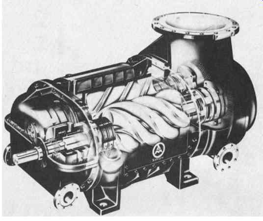
FIG. 1 Modern rotary screw compressor. (Aerzener Maschinenfabrik GmbH, D-3258
Aerzen, Germany.)
The gaseous medium moves from the suction port to the discharge port, entrapped in progressively decreasing spaces between the convolutions of the two helical rotors, being thus compressed up to the final pressure before it is discharged into the discharge nozzle. FIG. 2 illustrates this process.
On small rotary screw compressors, the housing is vertically parted on the suction side. Cylinder and discharge side plate are frequently combined in one housing. The housings of larger machines are often parted horizontally for easy assembly.
Rotors and shafts are milled out of one piece of either forged or stainless steel.
Some manufacturers provide rotors with synthetic coatings. Depending on service conditions, this may lead to a rapid drop in compressor efficiency due to loss of coating on the rotor edges.
Process gas machines incorporate direction of flow from the top to the bottom, thus facilitating liquid removal from the compression space whenever liquid is injected into the rotor chamber for cooling or cleaning during operation. On-stream cleaning is highly advantageous in services where gases are contaminated or tend to polymerize. The sealing area is equipped with connections for sealing medium supply and relief. In principle, it is possible to apply a cooling medium to the cylinder wall, but uncooled cylinder housings can be used as well.
The principal components of a large, two-stage rotary screw compressor are shown in FIG. 3.
FIG. 4 illustrates typical rotor combinations incorporating an asymmetrical rotor profile. The profile combination 4 + 6 means that the male rotor has four teeth and the female rotor, six. Due to this profile combination, the diameter of the rotor core is relatively thick. This allows for operation with large differential pressures.
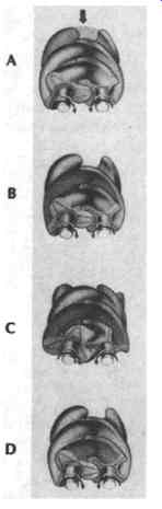
FIG. 2 Compression process in rotary screw compressor. (A) Suction intake:
Gas enters through the intake aperture and flows into the helical grooves
of the rotors, which are open. (B and C) Compression process: As rotation
of the rotors proceeds, the air intake aperture closes, the volume diminishes,
and the pressure rises. (D) Discharge: The compression process is completed,
the final pressure is attained, the discharge commences. (Aerzener Maschinenfabrik
GmbH, D-3258 Aerzen, Germany.)
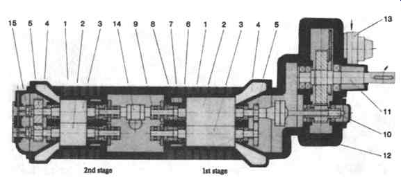
FIG. 3 Principal components of a two-stage rotary screw compressor. 1- Housing;
2- male rotor; 3-female rotor; 4- side plate on intake side; 5-timing gears;
6- graphite ring shaft-seal; 7-oil seal; 8- radial bearing; 9-axial thrust
bearing; 10-torsion shaft; 11- drive shaft; 12- step-up gears; 13- oil pump;
14- coupling; 15- compensating piston. (Aerzener Maschinenfabrik GmbH, D-3258
Aerzen, Germany.)
Bearings
Although air machines are often equipped with rolling element bearings, the majority of compressors for process gas applications are furnished with journal beatings and thrust bearings of the type commonly found in centrifugal process gas compressors. The service life of these beatings is practically unlimited as long as proper lubricating and operating procedures are in force.
Seals
In many rotary screw compressor applications, it is necessary to provide a sealing barrier between the process gas and the beatings. A number of different seal types are feasible:
++carbon ring seals
++barrier water floating ring seals
++double-acting mechanical seals with stationary spring
++combined floating ring/mechanical seals
At the compressor input shaft, manufacturers often opt for:
++labyrinth seals, or
++double-acting mechanical seals with rotating springs
Carbon ring seals with connections for the injection and education of neutral, clean gases are used in cases where leakage gas, even in connection with sealing gas, may enter into the beating areas or into the atmosphere. The gas pressure is relieved across floating carbon tings at the beginning of the seal chamber.
With barrier water floating ring seals, barrier water enters the seal chamber and a small amount of water reaches the compression space. Most of the water is returned to the barrier water system for cooling, filtration, and re-use. Barrier water seals are able to fully prevent gas leakage and can provide valuable cooling and scrubbing duties. FIG. 5 depicts a flow diagram for a single-stage screw compressor with barrier water seals.
A double-acting stationary spring mechanical seal and a combination mechanical and floating ring seal are primarily used for compression with high differential pressures.
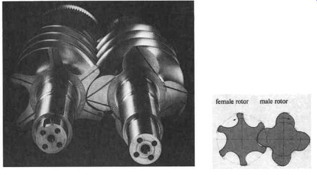
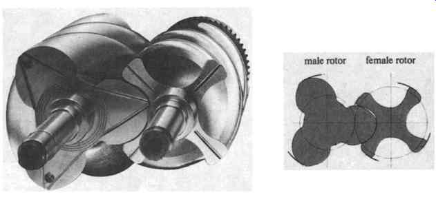
FIG. 4 Asymmetrical rotor sets for modem rotary screw compressors. (Aerzener
Maschinen-fabrik GmbH, D-3258 Aerzen, Germany.)
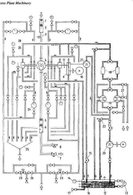
FIG. 5 Water sealing flow schematic. 1- Lateral compensator ss*; 2- starting
strainer; 3- water injection; 4- screw compressor; 5- lateral compensator
ds*; 6 - discharge silencer; 7- non-return valve; 8 - safety relief valve;
9- gear box; 10- drive motor; 11-coupling; 12-oii reservoir (base plate);
13-oil sight glass; 14-level controller (oil); 15 - non-return valve; 16
- oil heating; 17 - oil drain; 18 - twin oil filter; 19- twin oil cooler;
20- oil pump with motor; 21- gear box oil pump; 22- safety relief valve (oil);
23- barrier water controller; 24-flow indicator; 25- barrier water return;
26- valve; 27- slide valve; 28 - manometer. (*ss - suction side; ds - discharge
side). (Aerzener Maschinenfabrik GmbH, D-3258 Aerzen, Germany.)
Operating Principles for Oil-Injected Compressors
Regardless of whether the screw compressor is executed for dry compression or oil injection, the gas is compressed in chambers progressively decreasing in size that are formed by the intermeshing action of the helical rotors and by the housing wall. However, oil-injected compressors do not incorporate timing gears. Instead, the driven male rotor interacts directly with the female rotor without use of timing gears. Oil injected into the compressor cavity provides intensive lubrication, and a large portion of the compression heat is absorbed. At the same time, the clearances between rotors and cylinder walls are filled with oil. This prevents the reverse flow of compressed gas and increases the overall efficiency of compression.
At the compressor discharge flange, gas and oil exit through a check valve to the oil reservoir where most of the oil is separated from the gas. The remaining oil is separated in a downstream separator, and residual oil amounts of typically 5 parts per million (ppm) continue to remain in the gas stream. Oil carryover can be further lowered by downstream cooling and final moisture separation. The oil separation unit has to be properly maintained and the pressure drop across the separator cartridges taken into account to determine the overall performance of the compressor package.
It should also be recognized that the efficiency of oil separation depends on the degree of contamination of the separator elements.
The principle of oil separation is shown in FIG. 6, and a typical oil-injected screw compressor is illustrated in FIG. 7.
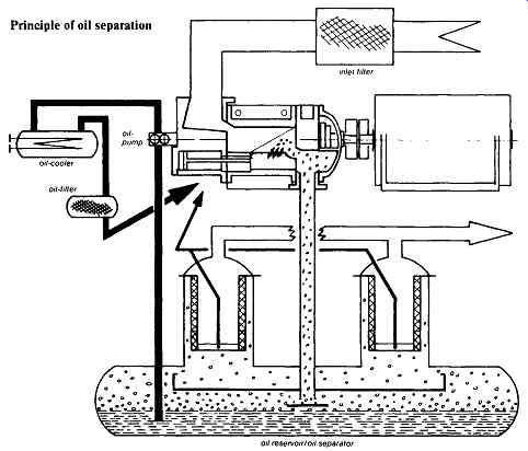
FIG. 6 Principle of oil separation used with oil-injected rotary screw compressors.
(Aerzener Maschinenfabrik GmbH, D-3258 Aerzen, Germany.)
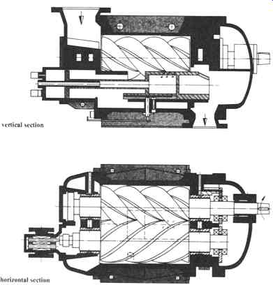
FIG. 7 Oil-injected rotary screw compressor cross section showing slide
valve for capacity control. (Aerzener Maschinenfabrik GmbH, D-3258 Aerzen,
Germany.)
Compressor Volume Control
In principle, it is necessary to consider the problems of volume control for dry-running and for oil-injection-type screw compressors separately.
Dry Screw Compressors
Control by Variable Speed. In consequence of the fact that screw compressors displace the medium positively, the most advantageous method of achieving volume control is that obtained by varying the speed. This may be done in any of the following ways:
++by variable speed electric motors
++by use of a torque converter
++by steam turbine drive
Speed may be reduced to about 50 percent of the maximum permissible speed.
Induced flow volume and power transmitted through the coupling are in this manner reduced in approximately the same proportion. The allowable turn-down depends on the adequacy of bearing lubrication at low speed and compressor discharge temperature. More than 50 percent reduction is possible in special cases. As mentioned earlier, there is no surge limit for these positive-displacement machines.
Bypass. Using this method, the surplus gas volume is allowed to flow back to the intake side by way of a compressor discharge pressure controller. An intermediate cooler brings the surplus gas volume down to intake temperature.
Full-Load/Idling-Speed Governor. As soon as a predetermined final pressure is attained, a pressure controller operates a diaphragm valve that opens a bypass between the discharge and suction sides of the compressor. When this occurs, the compressor idles until pressure in the system drops to a predetermined minimum value. The valve will close once again on receiving an impulse from a pressure sensor. This brings the compressor back to full load.
Suction Throttle Control. This method of control is suitable for air compressors only. As in the case of the full-load/idling-speed control method, a predetermined maximum pressure in the system, for example in a compressed air receiver, causes pressure on the discharge side to be relieved down to atmospheric pressure. Simultaneously, the suction side of the system is throttled down to about 0.15 bar absolute pressure. When pressure in the entire system has dropped to the permissible minimum value, full load is once again restored.
Screw Compressors Equipped With Oil Injection
Suction Throttle Control. Since the final compression temperature is governed by the injected oil, a greater range of compression ratios, such as may arise when the induced volume is throttled down, can be safely coped with. This permits the main flow volume to be varied within wide limits.
Built-in Volume Governor. Large compressors are frequently equipped with an internal volume-regulating device. By operating a slide valve (FIG. 8) that is shaped to match the contours of the housing and that is built into the lower part of the housing, designed to move in a direction parallel to the rotors, the effective length of the rotors can be shortened. The range of this control mode is typically between about 10 percent and 100 percent. Compared with suction throttling, this type of control offers more efficient operation, as graphically represented in FIG. 9.
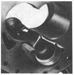
FIG. 8 Slide valve inside housing in partial capacity position. (Aerzener
Maschinenfabrik GmbH, D-3258 Aerzen, Germany.)
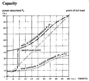
FIG. 9 Capacity versus power curve pertaining to oil-injected rotary screw
compressor. (Aerzener Maschinenfabrik GmbH, D-3258 Aerzen, Germany.)
Fall-off in power absorbed Pk expressed as a percentage of the full-load performance when operating at partial capacity and with the constants:
theoretical curve curve obtained in actual practice
....... curve obtained in actual practice by switching over from say 20 % capacity to idling speed (p~ = P2 = 1 bar)
........ curve obtained at idling speed (P~ = P2 = I bar).
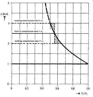
FIG. 10 Pressure-volume diagram for rotary screw compressor. (Aerzener Maschinenfabrik
GmbH, D-3258 Aerzen, Germany.)
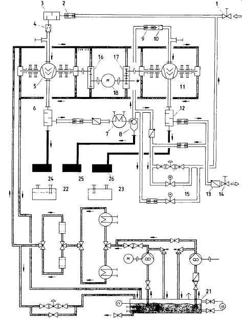
FIG. 11 Flow schematic for a two-stage rotary compression system. 1- Slide
valve; 2 - lateral compensator; 3 - intake silencer; 4 - starting strainer;
5- screw compressor 1st stage; 6-discharge silencer; 7-gas cooler; 8-separator;
9-lateral compensator; 10 - starting strainer; 11 - screw compressor 2nd
stage; 12 - discharge silencer; 13 - non-return valve; 14 - slide valve;
15 - control and shut-off devices; 16 - gear box 1st stage; 17-gear box 2nd
stage; 18- drive motor; 19-noise abatement hood (not shown); 20- noise abatement
hood (not shown); 21 - oil system; 22 - sealing water system; 23 - injecting
water system; 24 - condensate tank 1; 25 - condensate tank 2; 26 - condensate
tank 3. (Aerzener Maschinenfabrik GmbH, D-3258 Aerzen, Germany.)
Calculation Procedures
As was discussed earlier, the spaces in which the gas is trapped and progressively advanced are those formed between the cylinder walls and the interlocking convolutions of the two helical rotors. The position of the edge of the outlet port determines the so-called "built-in volumetric ratio," vi. The "built-in compression ratio," zri, results from the equation 7/" i = vX. * The compression process is shown in the theoretical p-v-diagram (FIG. 10). The induced flow volume may be calculated for any compression ratio, provided the data applicable to the particular compressor being considered are known. One revolution of the main helical rotor conveys the unit volume, q0 (liter/rev). This gives us the theoretical induced flow volume, Q0, at n revolutions:
The actual induced flow volume, Qi, is lower by the amount of gas, Qv, flowing back through the very small clearances. Thus ...
The slip loss volume Qv is mainly dependent on the following individual factors"
++total cross section of clearances
++density of medium handled
++compression ratio
++circumferential speed for rotor built-in volumetric ratio
Volumetric efficiency is…
The theoretical power input required to compress the induced flow volume, Qi, is
The theoretical power input requirement is increased by the dynamic flow loss, Pdyn, and by the mechanical losses, Pv. The latter consist of the losses in bearings, timing gears, and step-up gears. Thus, the power transmitted through the coupling is…
Pk : Pth + Pdyn -+- Pv [kW]
Screw compressors are manufactured to American Petroleum Institute (API) 619 and/or VDI 2045 standards with a permissible tolerance of -t-5 percent in regard to power requirements and induced flow volume. These tolerances result from inaccuracies introduced during the manufacturing process. The final compression temperature is calculated for a dry-type compressor as follows:
When operating on the oil-free, dry-running principle, a screw compressor may attain a maximum final compression temperature of 250 degree When air is the medium handled, this temperature (isentropic exponent X = 1.4) corresponds to a compression ratio of ...
On the other hand, gases with a X - 1.2 will permit, within the temperature limits mentioned, a compression ratio as high as ....
In the case of a screw compressor operating on the principle of oil injection, most of the drive energy applied to the machine is removed by the oil in the form of heat. The amount of oil injected is adjusted to ensure that final compression temperatures of approximately 90 deg. are not exceeded. When taking in air under atmospheric pressure, compression ratios as high as P2/P1 ~ 21 are obtainable.
Typical Flow Schematic
FIG. 11 represents a flow schematic for a two-stage rotary screw compression
system.
ROTARY PISTON BLOWERS
Rotary piston, or lobe-type, blowers derive from the Roots compressor principle and have been built since 1864. They are used in a large variety of process plant applications, including pneumatic conveying of bulk materials, pressurized aeration of water at treatment plants, creation of vacuum, and gas movement in the petrochemical, pharmaceutical, and metallurgical industries. They range in size from fractional horsepower to literally hundreds of kilowatts.
Design and Construction
Rotary piston blowers are twin-shaft rotary machines. The two rotors are axially parallel to one another and located centrally inside the casing. The timing gears ensure that the rotors turn without contact. The rotors are supported on ball and roller bearings. The clearance between the rotors is kept to a minimum and selected for the expected pressure differential and thermal load under working conditions.
Smaller rotors are adjusted in such a manner as to enable them to be run in either flow direction. Large blowers and gas blowers of special design are suitable for flow in one direction only, since in this case the clearances between the rotors and the casing must be kept larger on the low-pressure side to compensate for shaft deflection and bearing clearances. Axial thermal expansion of the rotors is compensated for by larger clearances between the rotors and the end plates at the free bearing end, i.e., at the bearing that is permitted to slide so as to accommodate thermal growth.
The shaft diameter is a very important factor in the evaluation of rotary lobe blower quality. It determines the amount of deflection and thus the magnitude of clearance and volumetric efficiency under load. Adequate bearing span provides space for proper sealing components between compression chamber and bearing housings. Needless to say, well-designed seals prevent contamination of gas by the lube oil and vice versa. This extends the life of bearings and gears.
The principal construction features of rotary piston blowers include driving and driven rotors, timing gears, beatings, and seals (FIG. 12).
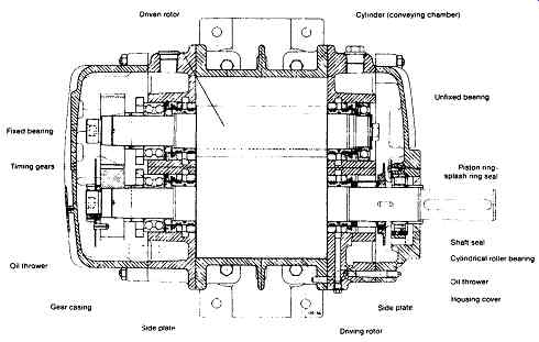
FIG. 12 Principal parts of a rotary piston blower. (Aerzener Maschinenfabrik
GmbH, D-3258 Aerzen, Germany.)
Method of Operation
Two symmetrical rotary pistons revolve in opposite directions timed to one another.
The medium to be conveyed flows into the blower housing that surrounds the two rotors. From there, it is moved via positive displacement in the chambers formed between the rotors and the housing toward the discharge side. At the instant when one rotor tip passes the edge of the discharge port, the gas is compressed by the back flow from the discharge port as can be visualized from FIG. 13. The final pressure adjusts itself to the pressure loss in the piping and in the plant equipment downstream from the blower.
The capacity of a given blower can be calculated for all types of gases and for every possible load condition. Each revolution of the rotors causes four separate volumes q0/4 (liters/revolution) to be conveyed and compressed. The power transmitted through the blower coupling is:
P = Pth --b Pv(kW)
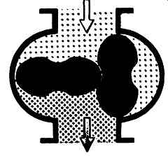
FIG. 13 Operating principle for rotary piston blower. (Aerzener Maschinen-fabrik
GmbH, D-3258 Aerzen, Germany.)
The main component, the theoretical power for compression, is thus independent of the type of gas involved and directly proportional to the working pressure differential and to the blower speed. Since no compression occurs internally, power absorbed when running under no-load conditions is nearly equal to the power loss, Pv. This will be approximately 3 to 5 percent of the power transmitted by the coupling when running on full load.
Rotary piston blowers are typically manufactured with a tolerance band of 4-5 percent, referred to the power consumption and the intake volume. These tolerances are composed of the sum of all manufacturing tolerances. This results in the theoretical capacity…
The actual capacity is obtained by taking the theoretical capacity and reducing it by the amount of gas, Qv, flowing back through the clearances:
The clearance losses depend on the specific density of the gas at intake, Ap, and on the total area, F, of the clearances. Volumetric efficiency is …
Since the rotor clearances are extremely small, efficiency under working conditions is high. The capacity varies very little with changing loads (FIG. 14). The amount of power needed to compress the capacity, Q1, is theoretically…
This power is in actual fact further increased by mechanical friction in beatings, timing gears, and sealing elements, and also by the dynamic losses occurring within the blower parts and in the compression chamber.
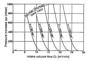
FIG. 14 Volumetric characteristics of a small rotary piston blower. (Aerzener
Maschinenfabrik GmbH, D-3258 Aerzen, Germany.)
===
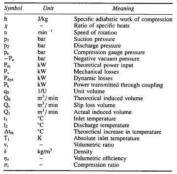
TABLE 1 Nomenclature Typically Used for Rotating Positive Displacement Calculations
Symbol Unit Meaning
Meaning: Specific adiabatic work of compression Ratio of specific heats Speed of rotation Suction pressure Discharge pressure Compression gauge pressure Negative vacuum pressure Theoretical power input Mechanical losses Dynamic losses Power transmitted through coupling Unit volume Theoretical induced volume Slip loss volume Actual induced volume Inlet temperature Discharge temperature Theoretical increase in temperature Absolute inlet temperature Volumetric ratio Density Volumetric efficiency Compression ratio
===
Capacity Control
The capacity of rotary piston blowers can be controlled by either varying the speed or by bypassing flow from discharge back to suction. Speed variation is, of course, the more efficient method, and turndown capacities of 70 percent can be reached in some cases. Power demand and pressure rise are almost directly proportional to blower speed.