AMAZON multi-meters discounts AMAZON oscilloscope discounts
APPENDIX A
Performance Calculations
Performance calculations are made to determine the throughput of a reciprocating compressor and the horsepower absorbed by the process.
The capacity throughput is determined by the displacement rate of the compressor, i.e., the volume swept by piston or pistons, the actual suction volumetric efficiency, and the specific volume at suction conditions. The volume swept by the piston(s) is determined by the total piston area, the piston stroke, and the piston speed.
In the case of a multistage compressor, the calculations must be performed for the first stage only, and the pressure ratio of the first stage has to be used. However, this does not mean that the following formulas cannot be used for each individual as well.
The actual volumetric efficiency is defined as follows: actual suction volume k= % volume swept by piston(s)
In order to calculate this value, the theoretical volumetric efficiency based on ideal gas conditions and not considering efficiency losses of any kind must first be determined ( FIG. A- 1).
…
where Vo = clearance volume (or space) expressed as percentage of the swept volume P2 = absolute discharge pressure of the first stage p~ -- absolute suction pressure of the first stage k = exponent of the re-expansion curve c-d
As a rule, the specific heat ratio is used for the sake of simplicity. The actual re-expansion curve deviates from the isentrope obtained in this way, and the difference has to be included in the coefficient of correction x (see below). This theoretical efficiency has to be corrected by x in order to obtain the actual volumetric efficiency:
X=r/-x%
Correction x allows for all influences that decrease the volumetric efficiency, such as pressure losses across the valves increasing the pressure ratio, preheating of the gas in the suction chamber resulting in a decrease of its specific weight, deviation from ideal gas law (compressibility factors at both suction and discharge conditions), and internal gas leakages. Test results determine x. It is normally between 3 and 10 percent.
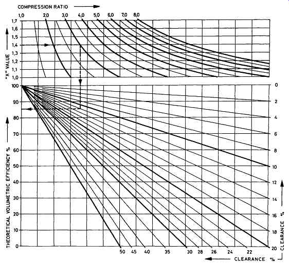
FIG. A-1 Theoretical volumetric efficiency versus clearance volume, compression
ratio (pressure ratio PI/P2), and K value. Example: K- 1.4; compression ratio-
3; clearance volume- 12%; theoretical volumetric efficiency - 85.5%. (Sulzer-Burckhardt,
Winterthur and Basel, Switzerland.)
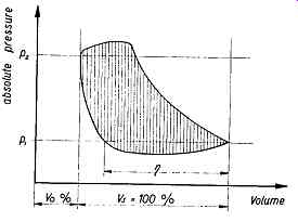
FIG. A-2 P-V indicator diagram, with shaded area representing work required
to compress and deliver the gas. (Sulzer-Burckhardt, Winterthur and Basel,
Switzerland.)
POWER REQUIREMENT
At a very early stage of each project in chemical engineering and in many cases before compressor manufacturers can be approached for quotations, the chemical engineer is confronted with at least three questions:
1. How big is the compressor I need?
2. What initial investment is required?
3. How much power is required?
Since the key to answering the first and second question is the power consumption, it may be useful to have a formula at hand, by means of which it is possible to work out at least an approximate figure for the power absorbed at the compressor shaft.
The basic theoretical single-stage horsepower formula is developed for the pv indicator diagram, the net area of which represents the work required to compress and deliver the gas. This is represented by the shaded area in FIG. A-1. Unlike the diagram of the ideal cycle, the indicator diagram describes the real cycle and includes the pressure losses across the valves.
The actual power requirement is related to a theoretical cycle through an overall efficiency that has been determined by test on prior machines. The overall compressor efficiency is the ratio of theoretical to actual power on the compressor shaft.
As a rule, reciprocating compressors are compared with the isentropic (adiabatic) cycle. Since this leads to a somewhat complicated formula, a good many engineers still use the isothermal power as a basis, as in the formula below:
Pis = R x T l x In P__!2 P~ where R -- gas constant
T = absolute suction temperature
Since this is a general formula saying nothing about the type of compressor or the number of stages, it can also be used for multistage compressors provided that P2/P1 is the overall pressure ratio and not only the pressure ratio of one stage.
Using algebra, the above formula can be converted into the following ones, which are better suited for practical use:
Power absorbed in horsepower:
Power absorbed in kilowatts:
where Pl -" absolute suction pressure in psia P2 = absolute discharge pressure in psia V1 --actual suction volume in acfm r/is - overall efficiency based on isothermal power
Overall efficiency based on isothermal power (rlis) is a figure that must be stated by the compressor manufacturer. In most cases, it is between 0.55 and 0.70 (55 to 70 percent). The value of rlis depends on many factors and its magnitude can be influenced only in part by the compressor manufacturer. It is mainly determined by the following:
++gas to be compressed (specific heat ratio, molecular weight, compressibility factors)
++size and type of compressor (as a rule, one 100 percent capacity compressor has a better efficiency than two 50 percent capacity machines)
++speed of the compressor (pressure losses in the gas stream)
++discharge pressure, pressure ratio
++number of stages
++intercooling with multistage compressors, i.e., the better the cooling effect, the better the efficiency
CONVERSION OF SUCTION CAPACITY
Compressor manufacturers state the actual suction capacity of their machines in acfm or cubic meters per hour, whereas chemical engineers prefer weight rates expressed in pounds per minute or pound moles per minute or flow rates expressed in standard cubic feet per minute (scfm).
The actual inlet volume may be calculated from the following formulas by using the proper inlet pressure and temperature and correcting for moisture content at these conditions and deviation from the ideal gas laws (compressibility): From weight flow (W) to acfm (W lb/min, dry)
where M = molecular weight T1 = absolute inlet temperature Pl -- absolute inlet pressure Z1 = compressibility factor, at intake conditions C1 -- correction factor for the moisture at intake
conditions dimensionless degrees Rankine ~ (/) psia dimensionless dimensionless
Z 1 depends on gas, pressure, and temperature. For ideal gases, Z 1 is 1. C 1 depends on moisture content, temperature, and pressure. For dry gases, C1 is 1. For atmospheric pressure, 14.7 psia, 68 degree and 100% relative humidity, it is 1.024. Use charts for ZI and C1.
APPENDIX B
Capacity Control
There are two main reasons why compressor capacity regulation is used. The most prevalent one is to adjust the suction flow to match the process demand. The second reason is to save energy. As a rule, capacity control is determined by compressor discharge pressure. In cases where the system upstream of the compressor has to be protected against too low a suction pressure, the control point may be governed by intake pressure. Modem control technology permits using other parameters as control points; temperatures, flows, liquid levels are but a few examples.
Where changes in demand are infrequent and slow, the capacity control may be arranged for manual operation, either directly on the compressor or by means of remote control. Modem process plants in which changes in demand are rapid and not always predictable, or where compressors have to be operated without supervision by operating personnel, require automatic control.
There are a number of variations that can be grouped under two branches of capacity control, as shown in FIG. B-1. The optimum capacity control is largely determined by the following parameters:
++the capacity range required
++how frequently changes in demand occur
++how long reduced capacity is required
++size of the compressor
++type of driver
Not all types of capacity controls can be used with a given compressor model, a specific pressure range, or a given gas. The process engineer involved in specifying the compressor should clearly describe the turndown requirements and work with the machine manufacturer in determining feasible capacity control strategies. It is sometimes necessary to combine two or more types of regulation for best efficiency, flexibility, and reliability. Table 14B.1 lists the main characteristics of the capacity control systems as described in FIG. B-1.
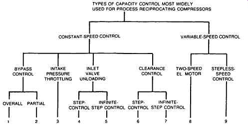
FIG. B-1 Types of capacity control most widely used for process reciprocating
compressors. (Sulzer-Burckhardt, Winterthur and Basel, Switzerland.) ---
TYPES OF CAPACITY CONTROL MOST WIDELY USED FOR PROCESS RECIPROCATING COMPRESSORS;
CONSTANT-SPEED CONTROL VARIABLE-SPEED CONTROL; BYPASS CONTROL; OVERALL PARTIAL;
INTAKE INLET PRESSURE VALVE THROTTLING UNLOADING; STEP- INFINITE- CLEARANCE
TWO-SPEED STEPLESS- CONTROL EL. MOTOR SPEED CONTROL; CONTROL STEP CONTROL;
CONTROL STEP CONTROL
Capacity control by means of an overall bypass can be applied without limitations to all compressors, provided that the gas recycled enters the suction line close to normal suction temperature. This means that an aftercooler or a bypass cooler may have to be used. In addition, a check valve in the discharge pipe is required to prevent the high-pressure gas from flowing back when the compressor is at standstill. Since this regulation is very uneconomical, it should only be used if the compressor has to be operated at reduced capacity for a short time or in combination with an energy-saving type of control.
In multistage compressors, a bypass around the first stage or a partial bypass can be used. The absolute power input can be reduced in this way, although the specific input is increased. In fixing the regulation range of a first-stage bypass, it must be remembered that a reduction of the flow to the second stage causes a drop of all interstage pressures, and consequently it can lead to excessively high pressure ratios and discharge temperatures in the following stages. These pressure shifts can cause overload in the last stage. Therefore, the recycled flow has to be restricted by means of an orifice plate in the bypass pipe. The minimum capacity that can be attained depends on the number of compression stages. The more stages used for a given overall compression ratio, the wider the achievable control range. For oxygen service, a partial first-stage bypass is normally the only recommended means of constant-speed capacity control apart from an inefficient overall bypass. With three-stage compressors, the minimum attainable capacity is approximately 60 percent. If a lower turndown capacity is required with such a compressor, the problem can be solved by providing an additional compressor stage or cylinder.
Bypass regulation are very practical and easy to apply. Standardized components can be used.
Intake pressure throttling will provide an infinite number of steps between full load and reduced load. Capacity changes are achieved by reduction in both gas density and volumetric efficiency, since the latter depends on the pressure ratio.
When this method is applied, it is again necessary to investigate beforehand the resulting changes in pressure, discharge temperatures, and load conditions in the upper stages. When compressing flammable gases, care must be taken not to create a vacuum in the suction pipe in order to avoid the ingress of air.
Inlet valve unloading is the most widely used type of constant speed control.
This consists simply of holding one or more inlet values open during both suction and discharge strokes, so that the gas taken into the cylinder on the suction stroke is pushed back through the suction valves on the discharge stroke. With one double-acting cylinder, two steps--50 and 0 percent--are possible. With two first-stage double-acting cylinders running in parallel, 75, 50, 25, and 0 percent capacity can be attained.
With multistage compressors and control range down to 0 percent, all suction valves have to be fitted with unloaders. The cylinder shown in FIG. B-2 is fitted with suction valve unloaders (A). The suction valve plates can be lifted either by means of threaded spindles with handwheels (not shown in the figure)
or by means of servomotors, as represented in FIGs. B-3 and B-4. These are operated either by oil pressure or, less frequently, by compressed air, or by the process gas.
TABLE 11.1 Main Characteristics of Capacity Control Systems
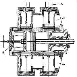
FIG. B-2 (A) Compressor cylinder with suction valve unloaders and (B) clearance
control. (Source-Burckhardt, Winterthur and Basel Switzerland.)
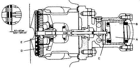
FIG. B-3 Suction valve unloader for reciprocating compressors. (A) Servomotor,
(B) main spring, (C) oil under pressure, (D) bell, (E) suction valve. (Sulzer-Burckhardt,
Winterthur and Basel Switzerland.)
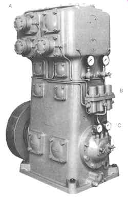
FIG. B-4 Single-stage labyrinth-piston compressor with two double-acting
pistons working in parallel. One cylinder is fitted with suction valve unloaders
(A) on both suction valves, while the other one has an unloader on the lower
suction valve only. The unloaders are actuated by oil pressure supplied by
the crankshaft-driven oil pump (C). The oil flow to and from the servomotors
is controlled by three solenoid valves (B) so that capacity steps of 75,
50, and 25 percent can be achieved. (Sulzer-Burckhardt, Winterthur and Basel,
Switzerland.)
When the servomotor (A) is deactivated, a spring (B)exerts pressure on the spindle, thus keeping the valve plate in the open position. The oil pressure is, as a rule, generated by the crankshaft-driven gear-type lubricating oil pump, which also supplies oil to the compressor beatings. This means that the suction valves are kept open by spring force when the compressor is idle. As a consequence, a compressor equipped with hydraulic suction valve unloaders is started up without load and begins to deliver gas only when the oil pump generates sufficient oil pressure.
When the compressor is running, its capacity is reduced in steps according to the number of suction valves kept open.
Infinite (stepless) control between 100 and approximately 50 percent of each individual suction valve and hence of each cylinder or cylinder half can be achieved by using springs between the servomotor spindle and the bell, which keeps the valve plate open. In this way it is possible to influence the time during which the gas is pushed back to the suction pipe at the discharge stroke. Valves controlled in this way are referred to as timed suction valves. By altering the spring force acting on the bell, the closing of the valve plate can be held up at any point between 0 and approximately 50 percent of the compression stroke, so that the flow can be adjusted continuously between 100 and approximately 50 percent.
The spring force depends on the position of the servomotor piston, which in turn depends on the oil pressure below the piston. Below 50 percent capacity, this control system jumps to the no-load position and the suction valve plates are then kept open permanently. This system also permits unloaded start of the compressor.
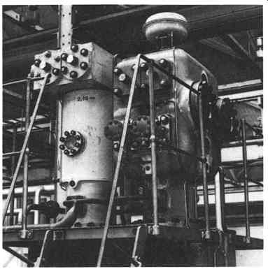
FIG. B-5 One-step clearance controls on vertical compressor cylinder (right
side, top). (Sulzer-Burckhardt, Winterthur and Basel, Switzerland.)
An example of a one-step clearance control is shown in FIG. B-2 (B) and FIG. B-5. Such a device is sometimes used in combination with valve unloading in steps. FIG. B-5 illustrates cylinders of a two-stage labyrinth-piston compressor compressing ethylene from 280 to 1215 psia. The first-stage cylinder (fight) is equipped with a one-step clearance control and with valve unloaders on the lower suction valves. The second-stage high-pressure cylinder has no capacity control. With this combination, steps of 73 and 60 percent can be achieved. Reducing the capacity in one cylinder only causes a drop of the interstage pressure, which could be tolerated in this specific case. The actuator for the clearance pocket control is operated by compressed air. The servomotors for the valve unloaders are actuated by oil pressure; however, the three-way valve controlling the oil flow is controlled pneumatically. The system is suited for manual as well as automatic remote control by means of a 60-psig compressed air signal.
All reciprocating machines have a clearance space, which is imposed by their design and which, particularly in compressors, is kept as small as possible. At the end of the compression stroke, this space is filled with the compressed gas. When the piston returns, the entrapped gas expands to the suction pressure before the suction valve can open and gas can flow into the cylinder. The larger the clearance space, the greater the loss of suction volume. Capacity control by additional clearance space is based on this fact. By artificially increasing the clearance space, the discharge quantity of the compressor can be regulated with only very slight losses.
In its simplest form, this additional space is in the cylinder cover, as shown in FIG. B-2, or is provided by a clearance bottle. By means of a valve, operated by hand, by air or oil pressure, or by a small electric motor, the additional clearance space can be added to the already existing one.
The practical application of this principle today consists in the inclusion of one, two, or more such additional spaces in the design of the cylinder cover, each fitted with suitable valves. With two additional spaces of different sizes, a and b, four stages of regulation--namely full load and the partial loads by connecting a, b, or a+b--can be attained. This method of regulation is reliable and economical, but it permits adjustment to fixed quantities only, so that it sometimes has to be combined with a bypass or suction valve control in order to bridge the intervals between the regulating steps.
Infinite stepless control by clearance space can be obtained if the additional clearance space is designed as a cylinder with a movable piston. Such a design, however, is far from simple and is generally expensive. This method of capacity control is therefore used very rarely, in spite of its technical advantage.
Permanent reduction of capacity by increasing clearance space is sometimes necessary if a compressor has to be operated at reduced flow for a relatively long period of time. In this case, capacity control systems are not the optimum solution.
Clearance space increases are achieved by lifting cylinder cover and/or compressor valves by means of distance rings. If valves are lifted in this way, the lanterns have to be replaced by shorter ones. The higher the compression ratio, the greater the reduction in capacity that can be achieved. In most cases, a reduction of 10 percent or more is feasible at little cost and with practically no loss in power efficiency.
When the full capacity is required again, the distance rings can be removed and the lanterns replaced by the initial ones.
VARIABLE-SPEED CONTROL
The optimum method of regulation is adapting the flow to process demand by changing the compressor speed. Variable-speed control is used whenever the driver is capable of operating at a speed commensurate with demand. Steam and gas turbines and internal combustion engines are in this class.
Most compressors today, however, are driven by electric motors. The simplest and least expensive method is to use a two-speed motor. However, two-speed operation may not be possible with large motors. The problem is aggravated by the fact that in contrast to dynamic compressors, reciprocating compressors have a constant torque over the full speed range. With direct current (DC) motors, a wide speed range can be attained, but DC drive systems can become very costly.
Recent developments in thyristor technology and electronic control made it possible to use adjustable frequency drives for large compressors, resulting in excellent overall efficiency. Adjustable frequency drives are very reliable and easier to maintain than other variable-speed electric motors. With adjustable frequency systems, both induction and synchronous motors may be used. A typical adjustable frequency drive system with electronic control consists of the following main equipment:
++a circuit breaker or motor starter
++a supply converter
++a DC link reactor
++a motor converter
++a brushless, alternating current (AC) synchronous motor
The use of variable-speed drivers creates some problems that deserve special attention:
++The flywheel effect decreases in proportion to the cube of the speed.
++Torsional and other vibrations could coincide with running speeds and cause damage to the machine.
++Gas pulsations in the pipe system must be kept under control over the full speed range.
++Poor lubrication of the compressor bearings occurs at minimum speed, particularly if the lubricating oil pump is driven by the crankshaft. This problem can be solved by means of an independently driven pump.
++It may be necessary to add some additional mass to the reciprocating parts of the compressor in order to ensure piston-rod load reversal at the bottom speed. In most cases, this reversal is required to maintain proper lubrication between the crosshead pin and bushing.
The above list, which is not complete, demonstrates that in certain cases it is not possible to utilize the entire speed range of a driver.
APPENDIX C
Higher Pressures on Dry-Running Compressors
In recent years, energy and environment considerations have led to a growing demand for dry running compressed gases in the chemical industry. A new sealing system was developed to enable reciprocating compressors to raise pressures about 100% more than previous limits.
Operators of compressor installations now demand at least 8000 hours of continuous running. At an average piston speed of 3.33 m/s the sealing and guiding elements cover a frictional distance of 96 000 km in the course of this-more than twice round the earth. During this time, the elements must neither fail nor permit unacceptable leakage rates. This applies also to compressors that have to run oilfree, as in the food industry, for example.
Oil-free ring piston compressors have dry-running sealing systems between the moving and stationary parts, which also guide the piston. Crosshead compressors, which are able to compress gas with the lower piston side additionally, are fitted furthermore with a likewise dry-running piston rod seal too, called a packing. These devices must seal very efficiently, otherwise leakages may result in process gas escaping into the environment. Such losses must be avoided with expensive gases. They are quite unacceptable when inflammable, corrosive or toxic gases are being compressed. Consequently, a great deal of engineering goes into the sealing arrangements.
Dry-running friction pairs function by reason of solid lubricants present in one of the friction partners. Very important here is the formation of a transfer film on the partner that does not supply lubricant. Tests with various metal-plastic pairings have shown that the coefficient of sliding friction is reduced from 0.3-0.6 to 0.1-0.3 after the formation of a transfer film.
As a result of the self-lubricating action, however, the partner supplying lubricant is gradually worn away, so that sooner or later it becomes necessary to replace the sealing and guiding elements.
Filled polymers with a matrix of polytetrafluoroethylene (PTFE) are employed mainly nowadays for sealing and guiding elements in unlubricated reciprocating compressors. Already decades ago, rings of this material ousted the previously predominating rings of carbon/graphite. However, pure PTFE is unsuitable for the purpose in question because its strength diminishes markedly under heating. Fillers matched to the particular application are therefore added to the polymer. Following the trend to unlubricated compression, the performance level of dry-running ring piston compressors has been raised progressively on the heels of the lubricated machines. The application limits are dictated by the properties of the dry-running materials used.
There has recently been a growing tendency to make use of high-temperature polymers like polyether ether ketone (PEEK), polyphenylene sulphide (PPS) or polyimide (PI). These likewise are not suitable in the pure form, and require additions of solid lubricants such as carbon/graphite, PTFE or molybdenum sulphide.
Rings of various plastic mixtures are now offered by virtually all suppliers in a wide variety of compositions and mixing ratios.
Some of these polymer blends have been used with eminent success in areas which were previously dominated solely by PTFE materials containing hard, abrasive fillers such as glass fibers or ceramics. Costly abrasion protection can be omitted as a result.
On the one hand, the oscillating motions of the reciprocating compressor are responsible for an inconstant behavior in time of the key variables in the total stress load, like the sliding velocity, surface pressure and operating temperature. On the other hand, owing to the functional principle of friction seals arranged in series there is no clear-cut distribution between the individual sealing elements. To investigate this, MSB operates a test stand based on a modified process gas compressor of the balanced-opposed type. It allows the pressure and temperature distribution in the packing to be measured as well as the gas leakage rate ( FIG. C-1). To enhance the sealing efficiency and reduce wear, the sealing elements are provided in multiple. Nevertheless, trials with various packing ring designs types did not yield the expected pressure distribution pattern. The differential pressure to be sealed was restrained mostly by one or two highly loaded sealing elements. The load was concentrated first on the elements at the edge of the packing, and when these became worn, it migrated inwards from both sides onto the next, previously unloaded elements till the entire packing was leaking.
FIG. C-2 shows the actual pressure reduction and the associated loading of the sealing elements.
Extensive trials on the test stand with various types of sealing elements made from the same material revealed that not only the leakage but also the temperature and above all the wear are influenced by the ring section geometry. This shows that the sealing elements are likewise significantly improved by their design. To exploit the potential present here, the "Kaskade" simulation program was developed by MSB, simulating the processes in a dry-running friction ring seal. Assisted by laboratory trials and test stand trials with piston and packing rings, it has been possible to advance the design of sealing elements till the frictional heat generated is minimal - a prime requisite for dry running.
With that it is possible to determine the admissible application limits for dry-running sealing systems according to the operating data of the compressor and to design dependable sealing systems.
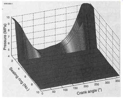
Fig. C-1 Pressure distribution measured in a dry-running piston rod seal.
After the dynamic pressure reduction at the first two rings, there is virtually
no further change till the pressure drops from 4MPa to ambient after the
10th ring pair. ( Sulzer-Burckhardt, Switzerland.)
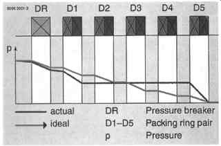
Fig. C-2 The green line plots the expected pressure reduction in serially
arranged friction seals. The measurement (blue line) shows, however, that
only the outer sealing elements are highly loaded. ( Sulzer-Burckhardt, Switzerland.)
The piston shown sectionally in FIG. C-3 has been developed specially for compressing very light gases to high pressures. The retained piston rings held at the upper part are provided exclusively for wear-free sealing of the dynamic pressure part, while the gastight twin rings following seal the static pressure component involving wear. By virtue of the stable separation of functions, with this design the compression of hydrogen to over 20 MPa (200 bar) is possible--completely oil-free. Previously no more than 10 MPA was attained, and this only with heavy gases. The improvement in piston rod sealing means the pressure has been raised from 4 to 10 MPa.
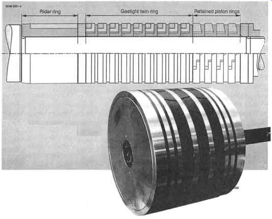
Fig. C-3 Dry-running, double-acting ring piston. With a similar piston having
the sealing arrangement shown here, hydrogen compression to 20 MPa has been
possible for the first time. ( Sulzer-Burckhardt, Switzerland.)