AMAZON multi-meters discounts AMAZON oscilloscope discounts
Compressors for the Production of Low-Density Polyethylene
A characteristic feature of the high-pressure ethylene polymerization process is that a very large difference in pressure is necessary between the inlet gas entering the reactor and the outlet of the recycled gas. The recirculators, generally called secondary compressors ( FIGs. 25 and 26), work between two limits, i.e., 100 to 300 bar on the suction side and 1500 to 3500 bar on the delivery side, for most of the existing processes. As the coefficient of reaction lies between 16 and 30 percent, the secondary compressors have to handle three to six times the quantity of ethylene that is polymerized, being thus by far the most powerful machines in the production loop. Their unit capacities, which when the industrial expansion first began were of 4 to 5 ton/hour, now lie between 15 and 118 ton/hour, and their power requirement per unit has been increased from 400 kW up to some 15,000 kW.
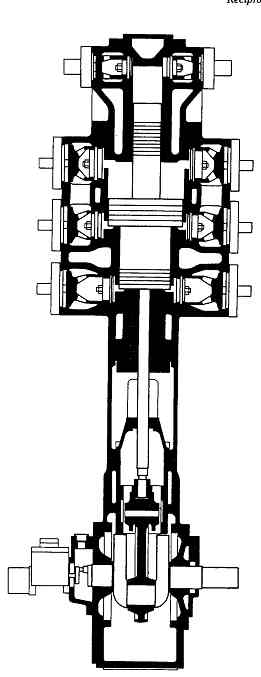
FIG. 24 Section view of acetylene compressor. (Sulzer-Burckhardt, Winterthur
and Basel, Switzerland)
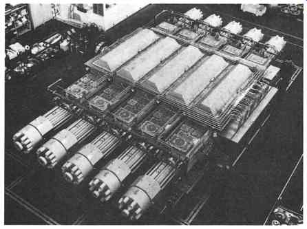
FIG. 25 Large secondary compressor (hyper compressor) (Sulzer-Burckhardt,
Winterthur and Basel, Switzerland)
As the whole operating range of these secondary compressors is placed well above the critical point of ethylene, the thermodynamic behavior of the fluid lies somewhere between that of a gas and that of a liquid. This peculiar condition has two main effects. The first is a very small reduction of the specific volume with increasing pressure; for instance, at a temperature of 25 degree the specific volume is 3 dm^3/kg at 100 bar, 2 dm^3/kg at 700 bar, and 1.5 dm^3/kg at 4500 bar. The second effect is a very moderate rise of adiabatic temperature with increasing pressure; for instance, with suction conditions of 200 bar and 20 degree the delivery temperature will reach only 100 degree at 2000 bar.
These particular thermodynamic conditions greatly influence the design of high-pressure ethylene compressors. Compared with the classical reciprocating compressor, the compression ratio is of little practical significance, the important factor being the final compression temperature, which should not exceed 80 to 120 degree depending on process, gas purity, catalyst, etc., in order to avoid premature polymerization. The influence of the cylinder head clearance on the volumetric efficiency is slight because of the small reduction of specific volume, and very high compression ratios are therefore possible with quite acceptable efficiency. In addition, the stability of intermediate pressures depends chiefly on the accuracy of temperatures; for instance, in the case of two-stage compression from a suction pressure of 200 bar to a delivery pressure of 2500 bar, a drop in the first-stage suction temperature from 40 to 20 degree will cause the interstage pressure to rise from 1000 to almost 1600 bar.
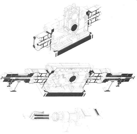
FIG. 26 Longitudinal sections through secondary compressor. The design of
this crank mechanism is based on a moving frame surrounding the crankshaft
and connecting the crosshead to the piston rods on either side. Thus the
crosshead pin is loaded with the difference between the piston-rod loads
only. (Sulzer-Burckhardt, Winterthur and Basel Switzerland)
For these reasons, a secondary compressor is required, which has only one or two stages, despite the very large pressure differences involved. However, this compels the designer to face extremely high mechanical strains due to the high amplitude of pressure fluctuation in the cylinders. Finally, an additional and sometimes disturbing feature of ethylene must be mentioned. If the gas reaches a very high pressure and a high temperature simultaneously (which can easily occur in a blocked delivery port owing to the very low compressibility), it will decompose into carbon black and hydrogen in an exothermic reaction of explosive character.
Cylinders and Piston Seals
Sealing of the high-pressure compression chamber is a major problem, and this could be solved by avoiding friction between moving and stationary parts. This has been realized for laboratory equipment and small-scale pilot plants by the use of either metallic diaphragms or mercury-based sealants in U-tubes, and such arrangements are still in use for research purposes. In addition, they have the advantage of avoiding any contamination of the compressed gas by lubricants. Unfortunately, chiefly for blocked delivery port owing to the very low compressibility), it will decompose into carbon black and hydrogen in an exothermic reaction of explosive character.
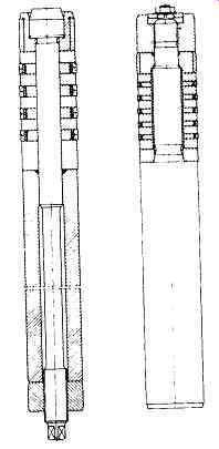
FIG. 27 Built-up piston designs for secondary compressors. (Sulzer-Burckhardt,
Winterthur and Basel, Switzerland)
Cylinders and Piston Seals
Sealing of the high-pressure compression chamber is a major problem, and this could be solved by avoiding friction between moving and stationary parts. This has been realized for laboratory equipment and small-scale pilot plants by the use of either metallic diaphragms or mercury-based sealants in U-tubes, and such arrangements are still in use for research purposes. In addition, they have the advantage of avoiding any contamination of the compressed gas by lubricants. Unfortunately, chiefly for seizure. Owing to the high modulus of elasticity, the amplitude of the "breathing" movement during internal pressure fluctuations is much smaller than with steel, and thus the stress variations in the expanded outer sleeves is appreciably reduced.
However, as these sintered materials have a very poor tensile strength, care must be taken to ensure that the inner sleeve is always under compression, even if the temperature increases. This is the main purpose of the external cooling of the liner and not, as is usual, to dissipate the heat of compression.
At present, plungers with packings of the self-adjusting type, as shown in FIG. 29, are most widely used. The packings are usually assembled in pairs, the actual sealing ring tangentially split into three or six pieces being covered by a three-piece radially cut section. Both are usually made of bronze, kept closed by surrounding garter springs, and held in place by locating and supporting steel plates. The sealing rings are pressed against the plunger by gas pressure, which corresponds to the pressure difference across the sealing elements. The supporting steel plates must also be thermally shrunk to resist the high variations in internal pressure. Unfortunately, the use of sintered hard materials is restricted by the fact that the supporting plates are subjected, in the axial direction, to heavy bending and shearing forces, which these materials generally cannot withstand.
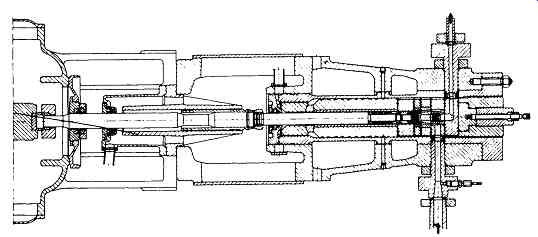
FIG. 28 Medium pressure cylinder for secondary compressor (hyper compressor).
(Sulzer-Burckhardt, Winterthur and Basel Switzerland)
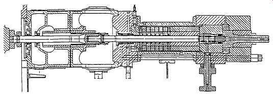
FIG. 29 Modem design cylinder with self-adjusting packing for secondary
compressor. (Sulzer--Burckhardt, Winterthur and Basel Switzerland)
The plungers for medium pressures are made of steel and plated with tungsten carbide. For very high pressures, the use of solid bars of hard metal is the best wear-resistant solution for plungers. The disadvantage of the packed plunger design lies in the much larger joint diameters of the static cylinder parts, which require two to three times higher closing forces than the piston ring design. Large cylinders, such as the one shown in FIG. 29, need a pretensioning of the cylinder bolts to about ten times the maximum plunger load. This ratio is higher for smaller cylinders.
For piston tings and packed plungers, the optimum number of sealing elements appears to be four or five. In both solutions, it is essential that the piston be accurately centered if the seals are to be effective; this is the reason for the guiding ring within or near the cylinder and for the additional guide at the connection between the piston and driving rod. At the base of the cylinder an additional low-pressure gland allows gas leaks to be collected and the plunger to be flushed and cooled.
Other separate glands positioned on the rod connecting the piston to the drive (FIG. 28) prevent the cylinder lubricant from mixing with the crankcase oil, and as the intermediate space is open to atmosphere, it is impossible for gas to enter the working parts.
From the point of view of design and maintenance, piston tings would appear to be the most adequate solution, and they are currently used for pressures up to 2000 bar or in some circumstances up to 3000 bar. The choice between them and the packed plungers depends largely on the process and type of lubricant used. One difficulty is that normal mineral oils are dissolved by ethylene under high pressure to such an extent that they no longer have any lubricating power. The glycerine used in earlier machines has been widely replaced by paraffin oil, either pure or with wax additives, which is much less diluted by the gas than other mineral oils.
However, it is a rather poor lubricant and is inferior to the various types of new synthetic lubricants, which are generally based on hydrocarbons.
Since part of the LDPE is used for the manufacture of plastic films and bags for the foodstuff industry, the ethylene to be compressed must not be contaminated by a toxic lubricant. At present, synthetic oils without toxic ingredients are used almost exclusively.
The basic difference between piston rings and plunger packings is that the latter may be lubricated by direct injection, while piston rings are lubricated indirectly.
This may be an advantage, since the low polymers carried by the return gas back from the reactor are reasonably good lubricants. However, too large an amount of low polymers causes the tings to stick in their grooves, and some kinds of catalyst carriers also brought back by the gas are excellent solvents for lubricants. Thus, the most convenient solution has to be selected for each specific case. In general, for higher delivery pressures (above 2000 to 2500 bar), better results are obtained with the use of packed plungers.
COMPRESSING DIFFICULT GASES
Difficult gases are those that require special attention by the compressor designer due to their specific properties. Very often standard compressors cannot be used for this service and the selection of the proper compressor type must be made very carefully in order to avoid misapplication and other costly consequences.
The following – incomplete - list demonstrates for which phenomena the compressor designer must be prepared when difficult gases are to be compressed.
These gases may:
++assume the liquid state in intercoolers
++decompose at high temperature
++polymerize
++dimerize
++produce the chemical reaction for which they are used already in the compressor cylinder
++form explosive acetylides in the presence of materials of construction promoting such a reaction
++attack the materials of construction
++cause hydrogen embrittlement
++dissolve materials used for gaskets
++dilute the lubricating oil and cause oil foam
++form an explosive and self-igniting mixture with air
++cause a fire (oxygen)
The compressor designer is normally confronted with two or even more of the above phenomena requiting precautions that very often contradict each other. This may explain why difficult gases are also referred to as nasty or unpleasant gases.
The answer to all these problems is a purpose-oriented design that is based on previous and occasionally costly experience. While with some gases the problem can be solved by selecting a suitable lubricant, other gases prohibit the use of any lubricant at all and oil-free compressors have to be used.
Typical unpleasant gases include the following:
++acetylene (see previous paragraph)
++chlorine
++hydrogen sulfide
++sour gas (i.e., wet gases containing hydrogen sulfide)
++hydrogen chloride
++sulfur dioxide
++carbon monoxide
[* For wet gases containing hydrogen sulfide (sour gas), see National Association of Corrosion Engineers Standard MR-01-75, Sulfide Stress Cracking Resistant Metallic Material for Oil Field Equipment, published by the National Association of Corrosion Engineers, Houston. ]
While these gases are normally inert to metals and do not attack the commonly used structural metals under normal conditions of use, they will corrode most normal materials of construction in the presence of moisture. Corrosion is accelerated at higher temperatures and pressures. Even if the gas is absolutely dry, corrosion may occur if atmospheric air is not prevented from entering the compressor. This means that the whole system has to be inserted carefully before and after overhaul services.
Normally, special materials have to be used for the gas-wetted parts of machines compressing difficult gases, and special precautions have to be taken in order to avoid leakage and to keep the gas temperature below the critical limit fixed in codes and standards for handling corrosive gases.* For chlorine, which is normally compressed to 145 to 175 psia in order to liquefy it, special compressors are available. Since this gas forms hydrochloric acid with oil and water, oil lubrication of the cylinders is out of the question. Compressors with sulfuric acid lubrication used earlier have now been replaced by dry-running machines with piston tings and rod-packing glands of carbon or plastic. Clean and dry chlorine has lubricating qualities, and the wear on the piston rings is astonishingly small. It is, however, essential that the chlorine be pure to prevent sealing tings sticking, and it is highly recommended to wash the chlorine gas with liquid chlorine from the liquefier before suction. Care must also be taken to prevent atmospheric moisture from entering the compressor in order to keep the gas dry and to prevent corrosion. The distance piece of these compressors has to be vented by means of dry air or preferably by dry nitrogen under a pressure slightly above atmospheric.
The free length of the rod in the venting chamber is greater than the piston stroke, so that traces of moisture adhering to the rod can never come in contact with chlorine. In order to keep the delivery temperature below approximately 180 degree chlorine compressors are usually made in three-stage designs for liquefaction at 175 psia.
COMPRESSORS WITH DRY-RUNNING PISTON RINGS
In contrast to the compressors described thus far, machines with dry-running piston tings and piston-rod-packing rings utilize no liquid lubricant, neither of a petroleum, synthetic, or other type, nor substitutes (for example, water) within the compression chamber. They belong to the group of nonlubricated compressors.
Basically, there are two different types of nonlubricated reciprocating compressors:
++dry-running compressors with piston rings and rod packing rings, which do not require lubrication
++frictionless, ringless labyrinth-piston-type compressors, which will be described later
The need for nonlubricated reciprocating compressors was first established in the United States by the brewing industry during the immediate post-prohibition period. This industry was in the market for machines supplying uncontaminated compressed air. To meet these requirements, it was decided to build a carbon piston ring compressor based on previous experience with carbon brushes on commutator and collector rings in the electrical industry, which indicated that a reasonable life might be expected. It is interesting to note that the first labyrinth-piston-type compressor, built in Switzerland at about the same time, was also designed upon request of a brewery for compressed air service (see later). Since the first appearance of nonlubricated compressors, these machines have gained a considerable market share. There are many reasons why nonlubricated compressors are used, and only the most important ones will be mentioned:
++Some gases do not permit the use of lubricating oils for safety reasons; oxygen is a typical example.
++Some gases attack lubricating oil, for example, chlorine.
++Lubricant contaminates gas stream (for example, instrument air, gases used in the foodstuff industry, and air and carbon dioxide in breweries).
++Lubricant carry-over fouls heat exchangers. This is an important factor in cryogenic cycles.
++No suitable lubricant is available for very low and very high temperatures (for example, boil-off compressors for liquid natural gas storage, steam compressors).
++Lubricant carry-over "poisons" catalyst.
Except for plant air, where the presence of trace amounts of oil may occasionally be welcome, there are no compression duties where contamination of the gas by lubricating oil is desired. For this reason, nonlubricated compressors are now used whenever possible and are commercially acceptable. However, when using nonlubricated compressors, one should bear in mind that the gas contains no oil to coat piping, pressure vessels, and heat exchangers. If these components are made of carbon steel, corrosion may occur.
Carbon used for piston rings and packing rings has been largely superseded in current practice by composition PTFE material, a fluorocarbon resin or plastic together with filler materials, such as glass fibers, bronze, and carbon. PTFE is not a self-lubricated material. The value of this material rests solely in its low coefficient of friction. Although only PTFE is mentioned here, the same comments would apply to future plastics, where improvements seem most likely. The plastics industry has developed low-friction materials for almost every gas. However, currently there is no universal material or compound that gives optimum service under all conditions.
Although new engineering plastics, which can withstand relatively high stresses and temperatures, have been developed, there are limits to be observed by the designer when using nonmetallic materials.
These limits are set by the following main factors, which may adversely influence the durability of PTFE piston tings:
++pressure
++temperature
++properties of the gas
++dirt
Compressors with piston tings and piston-rod-packing tings of plastic can normally be used for discharge pressures up to some 2900 psia. This, however, is not a fixed limit. With dry gases, excessive wear already occurs at much lower pressures. Some compressor manufacturers claim that they have built dry-running compressors for pressures as high as 4000 psia even for such exacting duties as bone-dry inert gases, e.g., argon and nitrogen. Unfortunately, they often neglect to publish the life or durability of the dry-running parts under these conditions.
The author knows of such a compressor compressing ammonia in three stages from 270 to 4000 psia where the piston tings of the third stage had to be replaced every 200 operating hours. For process compressors, where uninterrupted service of 8400 hours (one year with an availability of 96 percent) is required, a discharge pressure of 1500 psia should not be exceeded. For pressure between 1500 and 2900 psia, it is very doubtful whether 8400 hours of uninterrupted service can be achieved, and pressures above 2900 psia are in the experimental range for nonlubricated reciprocating compressors with PTFE piston tings.
A large number of nonlubricated compressors with a static suction pressure of around 5000 psia and a delivery pressure roughly 400 to 600 psi higher than the suction pressure- so-called re-circulators- have been successfully built. In these compressors, however, carbon tings have been used because PTFE did not withstand the high temperature created by friction heat. With carbon, an average life of 7000 operating hours has been reached. In the meantime, plastic materials have been developed for higher temperatures; however, it seems that these reciprocating re-circulators have been phased out by the CPI. Discharge temperature for dry-running compressors with PTFE piston rings should be held to a maximum of 350 degree in order to achieve acceptable durability of the piston rings. By properly staging a compressor, the temperature can be kept below the critical limit.
Other problems can arise from the gas itself. A bone-dry gas, such as nitrogen from a cryogenic air separation plant or boil-off gas from a liquid gas storage vessel, can cause severe ring wear. When compressing argon, a bone-dry inert gas with a specific heat ratio of 1.67, the wear problem is aggravated by the relatively high discharge temperature. For dry-running pistons, dirt is usually the most severe problem.
To overcome wear problems, some manufacturers propose so-called mini-lube cylinders. These machines belong to the category of lubricated compressors.
The design of nonlubricated compressors is basically the same as for compressors with cylinder lubrication, as described earlier, except for the high-pressure lubricators for cylinders and rod packings, which are not required.
In nonlubricated compressors, the compression chamber must receive no lubricant from any source, i.e., not even from the piston rod that normally traverses both crankcase and rod packing. There is a tendency for oil to creep along the piston rod despite the provision of scraper tings and the high pressure in the cylinder. The only way to properly combat this slight oil contamination is to incorporate an extra length distance piece between cylinder and crankcase, longer than the piston stroke, so that the oil-wetted portion of the piston rod does not travel into the rod packing.
In addition to this provision, a slinger has to be installed on the portion of the piston rod that passes into neither the cylinder packing nor the frame packing. Difficult conditions -- compression of highly explosive, toxic, or extremely flammable gases -- require the provision of a two-compartment distance piece with vent and purge connections.
Reciprocating compressors with dry-running piston rings and gland-packing tings can be built for power inputs up to several thousands kilowatts.
LABYRINTH-PISTON COMPRESSORS
Design Philosophy
In contrast to dry-running compressors of conventional design, as described earlier, the distinctive feature of the labyrinth-piston compressor is that no friction occurs in its gas-swept parts. Instead of piston rings, the labyrinth-piston compressor is provided with a large number of grooves producing a labyrinth-sealing effect against the cylinder wall, which is grooved as well. The piston moves with sufficient clearance so that no contact occurs between the latter and the cylinder wall. The same labyrinth-seal principle is used to seal the piston rod, so lubrication of the gland is unnecessary.
FIG. 30 shows a standard machine in cross section, where the oil-free side of the compressor is marked "A," while part "B" is lubricated in the usual manner.
This is achieved by using a crankshaft-driven gear-type pump that supplies the main bearings, the connecting-rod bearings, and the crosshead guide with pressurized oil.
The piston-rod guide bearings are splash lubricated.
Oil scrapers mounted above the piston-rod guide bearings remove the oil from the piston rod, and a slinger on the piston rod (not shown in FIG. 30) prevents the remaining oil film and oil droplets from entering the piston-rod gland. The distance between the crank gear and the gland has been so selected that the oil-wetted portion of the piston rod cannot reach the oil-free gland.
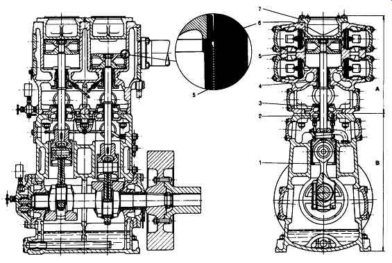
FIG. 30 Sections through a single-stage labyrinth-piston compressor. 1 -
Crosshead; 2 - guide bearing; 3- oil scraper; 4- gland with labyrinth seal;
5- piston with labyrinth grooves; 6- cylinder with labyrinth grooves; 7-
cylinder head. (Sulzer-Burckhardt, Winterthur and Basel, Switzerland)
Labyrinth-Piston Compressors versus Compressors With Dry-Running Piston Rings
Labyrinth-piston compressors have certain advantages but also disadvantages as compared with the oil-free compressors with dry-running sealing elements. As usual, the advantage of one compressor type are the disadvantages of the other one and vice versa.
The successful operation of filled PTFE rings in a dry-running compressor depends on the ability of the PTFE to coat the mating surface of cylinder bore and piston rod. Once the coating process is completed, the PTFE rings ride a film of the same material on the mating surface, minimizing ring wear. Until the PTFE coating is established on the mating surface of piston rod and cylinder bore, however, excessive wear of PTFE rings and packing will occur. Oil carryover by the oil scraper rings will tend to remove the PTFE coating from the piston rod and cylinder bore. This is why periodic inspection of such a compressor is necessary.
Another hazard is the possibility that pipe scale or welding beads will be drawn into the inlet. They too remove the PTFE coating. If the compressor is to be idle for some time, condensation can occur in the cylinder because of the temperature difference between the wet gas and the cylinder jacket water, and rust will eventually form on the bore. Even if the cylinder liner is made of stainless steel in order to prevent the formation of rust inside the compressor, in most cases rust can not be avoided in the gas pipes, heat exchangers, and pressure vessels unless these are made of non-rusting materials. Rust and other solid particles are not only a cause for removal of the PTFE coating but have a tendency to embed in the surface of the PTFE rings, which leads to rapid wear of the cylinder liner. Solid particles stem not only from rusty surfaces but in many cases from the catalyst. Below a certain size it is very difficult to remove them by means of suction filters.
This problem can be overcome in labyrinth-piston compressors, which have no friction in the gas-swept part. Consequently, they are not particularly sensitive to damage from dust-laden gases. A slight formation of rust in the cylinder can be tolerated, since the proper functioning of the compressor is not dependent on a smooth cylinder surface. This also means that inexpensive materials, such as carbon steel and cast iron, can be used.
One of the problems with dry-running reciprocating compressors stems from friction in conjunction with the materials used for piston rings. They set a limit to the pressure difference and discharge temperature of each stage. This problem, too, can be overcome with the contactless and frictionless piston, which does not depend on the use of nonmetallic parts. With labyrinth-piston compressors, pressures up to 4300 psia can be attained regardless of the temperature and properties of the gas. Even higher pressures are possible. Until 1988, the highest pressure attained with a labyrinth-piston compressor in industrial service was 6980 psia. The medium compressed was ammonia synthesis gas.
Apart from the rod-packing tings, which are made of graphite, no nonmetallic parts, which limit the temperature in the cylinder, are used. Since graphite is a high-temperature-resisting material, relatively high discharge temperatures can be tolerated. The temperature limit is then set by the gas itself, which may decompose, polymerize, or dimerize, or which may become corrosive above a certain temperature. With suitable cylinder materials and a purpose-oriented design, which keeps heat expansion within tolerable limits, very high and very low gas temperatures can be handled.
The disadvantages of a labyrinth-piston compressor as compared with a machine with piston rings stem from the labyrinth principle itself. High discharge pressures lead to small pistons in the final compression stage, with a corresponding unfavorable ratio of the ring gap surface area between piston and cylinder-to-piston area. Where light gases, such as hydrogen and helium, are being compressed, this ratio imposes a limit on the application of the labyrinth-piston compressor at significantly lower pressures than mentioned earlier. Whereas energy losses in the labyrinth can be negligible for the majority of gases, such losses can be considerable when light gases are being compressed, particularly to higher pressures. However, this does not entirely exclude labyrinth-piston compressors from hydrogen and helium service. A substantial number of these machines have been installed in cryogenic cycles with helium as a refrigerant.
Due to the labyrinth losses between piston and cylinder, it is natural that labyrinth-piston compressors cannot be miniaturized at will. Their capacity range is consequently limited, so the lower limit of a single-stage compressor is approximately 10 acfm at atmospheric suction conditions, while that of the multistage machines is considerably higher. For most gases, the minimum suction capacity at atmospheric suction pressure of a four-stage machine for a maximum discharge pressure of 3570 psia is around 100 acfm. These figures are quite different for a light gas, such as helium. A four-stage machine has been built for helium service, and for a suction capacity of 290 acfm at atmospheric pressure, a discharge pressure of 870 psia was attained.
These few examples demonstrate what is meant by the quote, "the labyrinth-piston compressor cannot be miniaturized at will." Smaller capacities, however, are not normally required by the CPI. Supercritical gas extraction processes may open in the future a field of application for small high-pressure labyrinth-piston compressors. For these machines, a different design will be required. The upper limit of the capacity range is governed by economic considerations; it is around 6500 acfm.
Labyrinth-piston compressors are available as standardized and custom-designed units. More than 30 frame sizes cover a power range from 20 to 2,000 kW. Labyrinth-piston compressors generally have a shorter piston stroke and are designed for higher speeds than compressors with piston rings. The reason why compressors with friction on the reciprocating parts have longer strokes and lower rotational speeds is obvious: the more strokes per minute, the more wear occurs at the points where the reciprocating parts change direction. On the other hand, a high rotational speed has a favorable effect on the labyrinth leakage in compressors with labyrinth pistons.
As mentioned earlier, the labyrinth sealing system has its price: labyrinth losses.
It has been claimed that labyrinth-piston compressors require more power than nonlubricated compressors with piston rings. This raises the question as to whether the power loss caused by mechanical friction of the piston rings and gland tings is smaller than the power loss caused by labyrinth leakage between piston and cylinder and in the piston-rod gland. Experience gained with both compressor types shows that for medium to large swept volumes per unit time and for gases that are not unusually light, the energy loss due to labyrinth leakage is about equal or even less than that caused by friction.
In order to obtain more accurate results, comparative tests on air were made with a vertical single-throw standard crank machine at a rated speed of 750 RPM and two single-stage double-acting cylinders and piston sets. The two cylinders had exactly the same dimensions. The only difference was the surface finish of the cylinder walls. Whereas one piston was of standard labyrinth design, the other was fitted with three plastic piston tings.
In both instances, exactly the same compressor valves, pipe work, measuring instruments, and drive elements were used. In this way, the differences in the operating characteristics could be reliably established without interference from side effects.
The comparison was made between the two series of tests on the basis of the following efficiencies:
p adiabatic r/a d -- p effective p isothermal
0is = p effective
The test results are plotted in FIG. 31 as a function of the pressure ratio at a speed of 600 RPM.
FIG. 31 Efficiency curves for a single-stage nonlubricated piston compressor.
( ) - isothermal; (- ) - adiabatic; o -piston with three plastic rings, single-stage, double-acting, 150 mm stroke; A - labyrinth piston; pl - intake pressure of 14.2 psia; P2 - discharge pressure. (Sulzer-Burckhardt, Winterthur and Basel, Switzerland)
Piston-Rod Glands
As mentioned previously, the piston-rod glands of labyrinth-piston compressors are also based on the labyrinth sealing principle. The sealing elements are of the floating-ring type. These rings have labyrinth grooves inside, facing the reciprocating piston rod. They are made of special grades of graphite. Their good dry-running ability, chemical inertness, and low thermal expansion coefficient are almost ideal for most gases to be compressed in the CPI. Frictionless packings cannot "run hot." The gland leakage is normally collected in a ring chamber at the lower end of the gland and vented back to the compressor intake. It does not represent a real loss of process gas ( FIGs. -32 and 33). In compressors handling air, nitrogen, oxygen, carbon dioxide, and other nontoxic and nonflammable gases, small gas losses to the surrounding atmosphere occurring at over-atmospheric suction pressure may be tolerated. They are vented to the atmosphere. In order to minimize this leakage, the lowest gland ring may be of the rubbing three-segment type with two garter springs around it and a smooth inner surface. Hot running of the lowest gland ring does not occur provided that the differential pressure across it is relatively small. For higher suction pressure, special gland designs are available. Labyrinth piston compressors as shown in FIG. 32 are used in these services.
In compressors handling toxic, flammable, or very expensive gases, such as carbon monoxide, hydrocarbons, hydrogen, helium, and argon, even very slight gas losses to the atmosphere cannot be accepted. For these services, hermetically closed compressors as illustrated in FIG. 33 are used. The only inevitable opening to the outside, which is the penetration of the crankshaft, is sealed hermetically in both stopped and running condition by means of a double mechanical seal immersed in an internal oil bath. This type of seal is effective even if the crankcase is under vacuum. The crankcase and the distance piece are filled with process gas and are subjected to suction pressure.
However, steps are taken to prevent the gas from carrying oil into the process.
Depending on the necessity, this may be achieved by an oil separator in the crankcase or by a molecular sieve built into the leakage return line outside the crankcase.
Practical results with closed refrigeration cycles have shown that the system remains free of oil even after such a machine has been in operation for years.
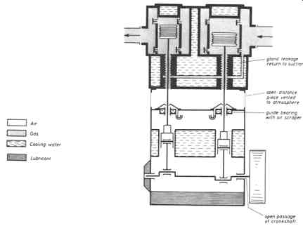
FIG. 32 Labyrinth-piston compressor, open type. (Sulzer-Burckhardt, Winterthur
and Basel Switzerland)
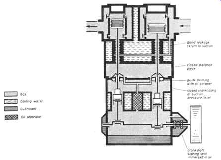
FIG. 33 Labyrinth-piston compressor with closed pressurized frame. (Sulzer-Burckhardt,
Winterthur and Basel Switzerland)
Basically all gases or gas mixtures that are compatible with lubricating oil can be compressed with these gas-tight compressors. They are also used in closed refrigeration cycles, particularly where low evaporation temperatures preclude the use of compressors with cylinder lubrication. Refrigerants used for this purpose are halogenated hydrocarbons, ethane, ethylene, and- for cryogenic cycles- helium.
In closed cycles, these compressors must be able to withstand standstill pressures occurring when the entire system is warmed up to ambient temperature. To date, compressors for a crankcase pressure of 300 psia have been built.
For toxic and corrosive gases that are not compatible with lubricating oil, neither the open-type nor the closed-type compressor can be used. Chlorine belongs to this class of gases. For such hardship cases, compressors with a strict separation between the oil-free cylinder and the lubricated crankcase have to be used. Since leakage to the environment is not allowed, special piston-rod glands have to be applied with vent and purge connections that can be flushed with a sealing gas, for example, dry nitrogen.
Piston-rod gland problems are often the decisive factor for the selection of the compressor type. It should be borne in mind that no piston-rod packing is entirely gas tight. As a rule, lubricated glands have less leakage than nonlubricated ones, since oil also acts as a sealant. Entirely encapsulated compressors with mechanical crankshaft seals give best results as far as tightness is concerned, since it is much easier to seal a rotating shaft than reciprocating piston rods.

FIG. 34 Three-stage oxygen compressor, 1700 acfm range. (Sulzer-Burckhardt,
Winterthur and Basel, Switzerland)
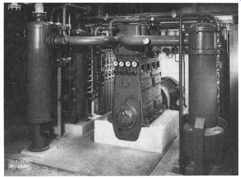
FIG. 35 Four-stage labyrinth-piston compressor in oxygen service. This machine
compresses 153 acfm to a discharge pressure of 3570 psia. (Sulzer-Burckhardt,
Winterthur and Basel, Switzerland)
Typical Applications For Labyrinth-Piston Compressors
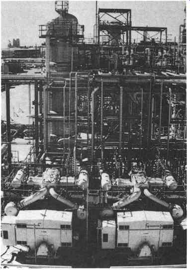
FIG. 36 Propylene compressors in a United States Gulf Coast petrochemical
plant. (Sulzer-Burckhardt, Winterthur and Basel, Switzerland)
Labyrinth-piston compressors are often the answer to problems occurring with other types of compressors. FIG. 34 depicts a three-stage oxygen compressor with a capacity of 1670 acfm and a discharge pressure of 600 psia. Since rubbing friction represents a source of ignition, frictionless labyrinth-piston compressors have found worldwide application in oxygen service. Packaged plants of the type shown with power ratings as high as 500 kW have been supplied.
FIG. 35 represents a four-stage oxygen compressor with a capacity of 153 acfm and a maximum discharge pressure of 3570 psia. With this compressor, dry oxygen and other dry gases can be compressed. In contrast to water-lubricated compressors, which are still widely used for this service, the gas remains dry and no dryer is required downstream of the machine. Two out of six two-stage propylene compressors located in a U.S. petrochemical plant are shown in FIG. 36.
Each of these compressors has a capacity of 2270 acfm and produces a discharge pressure of 300 psia. The compression ratio exceeds 10. These machines have performed admirably in a fouling service. Two skid-mounted two-stage labyrinth-piston compressors with pressure-tight casing are shown in FIG. 37. Compressors of this type have found worldwide application as boil-off compressors for the sea transport and storage of liquefied gases, such as hydrocarbons and ammonia. In most cases, the vapor is compressed in order to be re-liquefied and then recycled to the transport or storage tank. All suction valves are fitted with unloaders for unloaded start and capacity control. Compressors of this design are also used in refrigeration cycles.
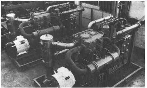
FIG. 37 Skid-mounted two-stage labyrinth-piston compressor with suction
valve unloaders. (Sulzer-Burckhardt, Winterthur and Basel, Switzerland)
DIAPHRAGM COMPRESSORS
Earlier in this section, FIG. 10 had assigned diaphragm compressors to the high-pressure low-flow range of application. Modem diaphragm compressors are often a combination of two systems--a hydraulic system and a gas compression system. A metal diaphragm group is the isolating component between these two systems.
In the diaphragm compressor depicted in FIG. 38, the gas compression system consists of three fiat metal diaphragms, which are clamped between two precisely contoured concave cavities and process gas inlet and outlet check valves.
The hydraulic system includes a motor-driven crankshaft that reciprocates a piston in the hydraulic fluid medium. This positive-displacement piston pulses the hydraulic fluid against the lower side of the diaphragm group, causing it to sweep the cavity, displacing the process gas. Except for very small diaphragm compressors, the other components of the hydraulic system are the automatic hydraulic injection pump, the hydraulic fluid check valve, and the hydraulic relief valve. In addition to ensuring that the hydraulic system is always full for the compression cycle, the automatic injection pump provides for fast priming of the hydraulic system after extended compressor shutdowns. On smaller compressors, this same function is sometimes accomplished by a manual priming pump and a gravity oil-feed system.
On the compression stroke of the main piston, the hydraulic check valve isolates the hydraulic system from the automatic injection pump or the manual priming pump so that an elevated pressure can be generated in the system against the hydraulic relief valve.
A full cycle of operation for the diaphragm compressor begins with the diaphragm group fully deflected to the bottom of the cavity by the gas suction pressure. The hydraulic piston is at bottom dead center, and the hydraulic system has just been filled by a single stroke of the automatic hydraulic fluid injection pump. On the process side of the diaphragm group, the cavity is now filled, at a given suction level, by the process gas that has entered through the inlet check valve. As the crankshaft rotates and the hydraulic piston moves from its bottom dead center position toward top dead center, the hydraulic pressure increases. This occurs because the hydraulic system injection and relief lines are blocked by the hydraulic check valve and relief valve, respectively.
As the piston continues toward top dead center, and as the hydraulic pressure reaches the pressure level of the process gas in the cavity, the diaphragm group begins to sweep the cavity toward its top dead center position, thereby compressing the process gas. When the pressure of the process gas in the cavity reaches the pressure level downstream of the discharge check valve, that check valve opens and the process gas is discharged from the cavity. Since the hydraulic system has slightly more displacement capacity than the gas system, the diaphragm group makes metal-to-metal contact with the process head cavity, assuring that all of the gas has been displaced. With the diaphragm group in this fully deflected discharge position, the piston still has a certain amount of travel required to reach its top dead center position. As the piston moves to top dead center, this additional hydraulic fluid volume is "over-pumped" through the hydraulic relief valve, which is set at a pressure level above the desired process gas discharge pressure. At this point, the compression portion of the cycle has been completed.
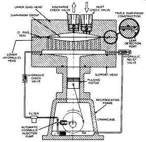
FIG. 38 Typical assembly of a diaphragm compressor. (PPI Division of the
Duriron Company, Inc., Warminster, PA)
The hydraulic piston now moves toward bottom dead center. As it does, the diaphragm group is deflected toward the bottom of the cavity by both the expansion of the residual gas contained in the clearance volume and by the additional process gas entering the cavity at suction pressure. During this suction stroke, a synchronized auxiliary eccentric cam on the crankshaft causes the hydraulic injection pump plunger to stroke, injecting an amount of hydraulic fluid equal to that which was "overpumped" through the hydraulic relief valve at the end of the compression portion of the cycle. On small gravity oil-feed units, hydraulic fluid is drawn from the crankcase as the main piston travels to bottom dead center. When the hydraulic piston reaches its bottom dead center position, the hydraulic system is again filled.
Since the diaphragm group is now in the bottom-most deflected position, a full gas cavity is assured. At this point, the cycle is complete.
The hydraulic pressure versus crank position has been plotted on FIG. 39.
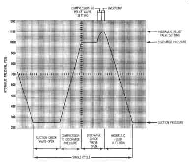
FIG. 39 Hydraulic system pressures acting over one operating cycle of typical
diaphragm compressor. (PPI Division of the Duriron Company, Inc., Warminster,
PA)