AMAZON multi-meters discounts AMAZON oscilloscope discounts
Reciprocating compressors are positive-displacement machines that compress and move gases by using a combination of rotational and linear (reciprocating) motion.
Reciprocating compressors are used for a variety of industrial services. Their basic function is to raise the pressure level of the gas being compressed. Doing so is desirable for the following reasons:
1. Storage and transmission of energy, e.g., shop air compression.
2. Reduction of volume for the purpose of storage and transport, including gas liquefaction. Typical examples are bottled gases for industrial uses, natural gas storage in underground reservoirs, storage and transport of liquid natural gas (LNG) and liquid petroleum gas (LPG), and compression of natural gas as a fuel for automobiles.
3. Transmission. Examples include pipelines for natural gas, ethylene and other hydrocarbons, ammonia, oxygen, and nitrogen.
4. Process. Chemical reactions that take place at elevated pressures (e.g., ammonia synthesis at 5,000 pounds per square inch absolute [psia]) are illustrative.
5. Energy conversion. Mechanical to thermal energy conversion (refrigeration systems, heat pumps) is an example.
Reciprocating compressors have inherent advantages over other compressors in their ability to adapt to a wide range of load, speed, pressure conditions, and pressure ratios (P_discharge/P_suction). The load may be varied from 0 to 100 percent; the speed may have a wide range, depending on the driver. Pressures may vary from a few inches of mercury absolute suction pressure in the case of a vacuum pump to 50,000 psia or more discharge pressure for process-gas compressors. Pressure ratios may vary from slightly over 1, in the case of natural gas transmission pipeline service, to 8 or more in the case of shop air compressors. Several stages of compression are often used when the overall pressure ratio is high.
There are many prime movers suitable for driving reciprocating compressors. These include electric motors, turbines, natural gas engines, diesel engines, and dual-fuel engines. Many electric motors and reciprocating engines have rotative speeds similar to those of reciprocating compressors and can be directly connected, eliminating speed reduction (or increase) between the prime mover and the compressor.
A typical compressor and principal internal construction features are shown in Figures 1 and 2.
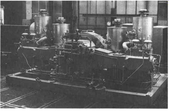
FIG. 1 Single-stage dry-running compressor with two horizontally opposed
cylinders for ethylene service. This machine is typical of small, skid-mounted
equipment. (Sulzer-Burckhardt, Winterthur and Basel, Switzerland)
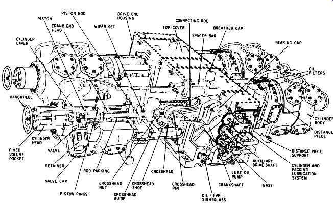
FIG. 2 Major internal parts of a large horizontally opposed reciprocating
compressor. (Transamerica De Laval, Trenton, NJ)
IDEAL COMPRESSOR CYCLE
Positive-displacement compressors are machines in which successive volumes of gas are confined within a closed space and elevated to a higher pressure. The reciprocating compressor is a special type of positive-displacement compressor that elevates the pressure of the trapped gas by decreasing the volume that the trapped gas occupies. A piston moving in a cylinder is used to reduce the volume of the trapped gas (FIG. 3). Compression
Referring to FIG. 3, note that the cylinder has filled with gas at the suction pressure with the piston at position a. The piston moves from a toward b, compressing the gas isentropically (with no heat transfer and no turbulent or frictional losses) until the pressure within the cylinder reaches the discharge-line pressure.
Discharge
At this point, the discharge valve opens and permits gas to flow from the cylinder into the discharge line until the piston has reached the end of its stroke at point c.
Expansion
Since it is impossible to build a compressor with zero clearance volume, gas remains in the cylinder clearance volume at the end of the discharge stroke. The gas remaining expands isentropically to suction pressure as the piston moves from c to d.
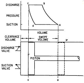
FIG. 3 Meal compressor cycle. (Transamerica De Laval, Trenton, NJ)
Suction
When the pressure within the cylinder reaches the suction pressure, the suction valve opens and permits gas at suction pressure to enter as the piston moves from d to
a. Since points b and d are determined by the pressures during the cycle, the cycle is described as having a suction stroke (piston moves from c to a) and a discharge stroke (piston moves from a to c).
CLASSIFICATION OF RECIPROCATING COMPRESSORS
Reciprocating compressors can be categorized as follows: I. Cylinder lubricated A. Trunk-piston type II. Cylinder nonlubricated A. Dry running piston tings B. Ringless type (labyrinth-piston type)
Other criteria for classification include arrangement of cylinder:
++vertical in-line
++horizontal (balanced-opposed)
++V-, L-, or W-arrangement
++integral with internal combustion engine and cooling:
++water-cooled
++air-cooled
Whether to use a compressor with a lubricated or nonlubricated cylinder is, as a rule, dictated by process requirements and the gas to be compressed. Some chemical processes do not permit the use of lubricants in the cylinders, even though the oil can be removed almost entirely by means of separators, filters, and the like, because the slightest traces of lubricant may "poison" the catalyst.
In this context, it must be remembered that since most separation methods are based on the difference between the specific weights of the gas and the lubricant, oil separation becomes more difficult with higher gas pressures. Lubricating oil cannot be used in compressor parts making contact with such gases as oxygen and chlorine.
Compressors with Cylinder Lubrication
Except for diaphragm compressors, machines with cylinder lubrication are the only reciprocating compressors generally available for pressures in excess of approximately 4300 psia.
Small compressors are, as a rule, trunk-piston machines. Their construction details (see FIG. 4) resemble automotive engines. For power inputs above approximately 100 kilowatts (kW), crosshead-type compressors are used. In contrast to the less costly trunk-piston types, compressors with crossheads permit the use of double-acting pistons. In other words, compression takes place during both forward stroke and reverse stroke of the piston.
Where contamination of the gas by lubricating oil cannot be accepted, compressors with water-lubricated cylinders may be used. The water can then be removed by means of a dryer. These compressors are used mainly for filling high-pressure cylinders, where small volumes of gas have to be compressed to relatively high pressures. Typical usage ranges are suction volumes from 12 to 160 actual cubic feet per minute (acfm), and discharge pressures from 2000 to 3600 psia.
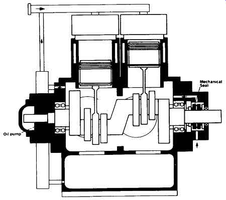
FIG. 4 Internal construction of a small trunk-piston reciprocating compressor.
(Sulzer-Burckhardt, Winterthur and Basel, Switzerland)
Compressors with Nonlubricated Cylinders
Compressors with nonlubricated cylinders are now used wherever possible. The occasional claim that if process permits, it is better to have a lubricated compressor, is not always borne out by the latest experience. Although tremendous progress has been made on nonlubricated compressors, where there is a choice between the oil-lubricated and nonlubricated type, the following factors must be considered:
++Nonlubricated compressors cost more than oil-lubricated machines.
++Nonlubricated compressors require more power.
++With the possible exception of frictionless compressors, nonlubricated compressors require more maintenance.
While there may be no ready answer to the question of lubricated versus nonlubricated compressor selection, the user should have little difficulty choosing the most applicable machine. A detailed investigation of service experience and maintenance frequency in a given service will be of great help to the specifying engineer.
COMPRESSOR ARRANGEMENT OVERVIEW
As mentioned earlier, reciprocating compressors can also be categorized according to the type and arrangement of their cylinders. Small compressors usually have single-acting, trunk-piston cylinders (see FIG. 5). Most of the higher horsepower units are double-acting, crosshead units (see FIG. 6). Double-acting compressors have pistons that compress gas on both ends so that one end is on its suction stroke while the other end is on its discharge stroke. The force resulting from the pressure and area differential across the piston is referred to as the piston-rod load. Reciprocating compressors are rated in terms of their rod-load capability rather than by horsepower. Rod-load ratings range up to 175,000 lb.
Higher horsepower compressors are built with a basic frame, and a wide range of cylinders that are interchangeable on the frame. The cylinders range from small-diameter high-pressure cylinders to large-diameter low-pressure cylinders. A line of cylinders is usually designed so that each cylinder matches the rod-load capability of the compressor frame at the maximum working pressure of the cylinder and the expected pressure ratio of the applications for which the cylinder is intended.
Double-acting compressors with cylinders of the type described above are designed as vertical in-line, vertical or horizontal straight-line, horizontal balanced-opposed, or "V"-or "L"-machines. Other cylinder arrangements are less common.
Multi-cylinder compressors with horizontal cylinders are very often designed as balanced-opposed type (see FIG. 7). The balanced-opposed frame is characterized by adjacent pairs of crank throws 180 degree out of phase and separated by crank webs only. With this configuration, the inertia forces are balanced if the reciprocating weights of opposing throws are balanced. The balanced-opposed design is a separable frame, thus the basic compressor can be driven by any number of prime movers, including diesel, natural gas and dual-fuel engines, gas and steam turbines, and electric motors.
Compressors driven by an internal combustion engine (e.g., diesel engine, gas engine) or by a steam engine can be designed as integral engine-compressor units, (FIG. 8; see also Section 4). The integral compressor has compressor cylinders and power cylinders mounted on the same frame and driven by the same crankshaft.
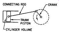
FIG. 5 Schematic view of a single-acting, trunk-piston machine. (Transamerica
De Laval, Trenton, NJ)
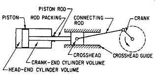
FIG. 6 Schematic view of a double-acting compressor design. (Transamerica
De Laval, Trenton, NJ)
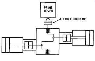
FIG. 7 Schematic view of a balanced-opposed compressor. (Transamerica De
Laval, Trenton, NJ)
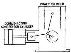
FIG. 8 Schematic view of an integral-type gas engine reciprocating compressor.
(Transamerica De Laval, Trenton, NJ)
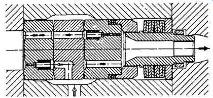
FIG. 9 Combination suction and discharge poppet valve for a secondary compressor.
(Sulzer-Burckhardt, Winterthur and Basel Switzerland)
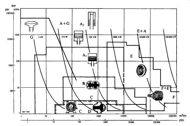
FIG. 10 Simplified capacity versus pressure diagram of the most widely used
types of compressors in the CPL Power consumption is approximate and is based
on a suction pressure of 1 bar (14.5 psia). (Sulzer-Burckhardt, Winterthur
and Basel, Switzerland)
Some integrals have in-line power cylinders mounted vertically and compressor cylinders extending from one or both sides in the horizontal plane. Others are V engines with compressor cylinders extending from one or both sides. For a more detailed description of gas engines, refer to Section 4.
Cylinder Heads and Valves
The design of the cylinder heads and valves is dictated by the fact that these parts have to withstand, for years, a pressure that fluctuates considerably, e.g., between 900 and 2500 bar at a frequency of 3 to 4 Hz. Modem methods of investigation led to designs such as that illustrated in FIG. 9, where inadmissible changes of combined strains could be kept within tolerable limits.
With large cylinders, combined suction discharge valves as illustrated in FIG. 9 are used for very high pressures. This valve is fitted with multiple suction and delivery poppets in order to reduce the moving masses. It is interesting to note that poppet valves, which were used in the last century, have experienced a comeback in compressors that are at the other end of a more than 130-year-old development of reciprocating compressor design.
Capacity Range of Reciprocating Compressors versus Other Compressors
The pressure-flow relationship of reciprocating compressors relative to other compressor types is illustrated in FIG. 10. Application ranges are identified as follows:
++A1: Reciprocating compressors with lubricated and nonlubricated cylinders
++A2: Reciprocating compressors for high and very high pressures with lubricated cylinders
++B: Helical- or spiral-lobe compressors (rotary screw compressors) with dry or oil-flooded rotors
++C: Liquid ring compressors (also used as vacuum pumps)
++D: Two-impeller straight-lobe rotary compressors, oil-free (also used as vacuum pumps)
++E: Centrifugal turbocompressors
++F: Axial turbocompressors
++G: Diaphragm compressors
The most frequently used combinations of two different compressor types are identified in three fields:
++A-t-G: Oil-free reciprocating compressor followed by a diaphragm compressor
++E-k-A: Centrifugal turbocompressor followed by an oil-free reciprocating compressor
++F+E: Axial turbocompressor followed by a centrifugal turbocompressor
The above list is never quite complete in either design or application, since compressor innovations enter the marketplace rather frequently.
For moderate pressures, rotary screw compressors compete with reciprocating compressors. Oil-free screw compressors are built for compression ratios up to 4.5 per stage. Two-stage units with atmospheric intake are available for discharge pressures up to approximately 195 psia and three-stage units are available with pressures up to approximately 300 psia. The oil-flooded screw compressor is available for a compression ratio up to 13 in single-stage and up to 21 in two-stage configurations. Booster screw compressors with elevated suction pressure are available for a variety of conditions, with pressure limits in the neighborhood of 260 psia unless special designs and materials are used. Rotor deflection limits the maximum attainable pressure difference.
Unlike reciprocating compressors, rotary screw compressors have a fixed built-in pressure ratio. This means that in some cases, higher compression than required by the process occurs inside the compressor, thus causing higher discharge temperatures. With fluctuating intake and discharge pressures frequently occurring in chemical process cycles, it is not always possible to operate a compressor at its built-in compression ratio. Low efficiency and high power consumption may be the result.
Sliding-vane Compressors are still widely used. Although they have limited discharge pressure capability (two-stage units are available with pressures up to 130 psia), sliding vane compressors cover roughly the same capacity range as the screw compressors. Since they are not oil-free, they have lost ground to dry-running screw compressors and are not covered in this text.
There are no clearly defined limits for the application in series of two or more compressor types. However, in series applications, many factors and alternatives influencing compressor selection must be considered (see later). Reciprocating compressors cover the range from the smallest capacity requirements through 10,000 m^3/hour (6000 cfm) and more. The reason why larger suction flows are normally handled by turbocompressors is the relatively high price of very large reciprocating compressors in comparison with turbocompressors. In the chemical processing industry (CPI), reciprocating compressors are typically found with power inputs up to 2000 kW, although standard frames are available with power inputs exceeding 10,000 kW. Most processes in the CPI require discharge pressures below 400 bar (5800 psia). The polymerization of ethylene to produce low-density polyethylene (LDPE) is an exception. This process requires discharge pressures between 1500 and 3500 bar (21,750 to 50,750 psia) and employs so-called secondary booster compressors with suction pressures between 100 and 300 bar (1450 to 4350 psia). Not only are these machines at the upper end of the pressure scale for chemical reactions, but they are also the most powerful reciprocating compressors built thus far. The power consumption of one existing unit is 15,200 kW! Reciprocating compressors for discharge pressures of roughly 8000 bar (116,000 psia) have been used exclusively in high-pressure research (see heading "High Pressure Compressors," later).
Oil-free compressors can be built up to about 300 bar (4350 psia) discharge pressure (see heading "Labyrinth-Piston Compressors"). Beyond this limit, high-pressure reciprocating compressors have lubricated cylinders. For oil-free compression to even higher discharge pressures, an oil-free reciprocating compressor followed by a diaphragm compressor may represent the best solution. The diaphragm compressor is discussed at the end of this section.
Trunk-Piston Compressors
As was mentioned earlier, in trunk-piston machines, the pistons are also the crossheads. Since there are no piston rods, this design is only suited for single-acting pistons, where the gas is compressed on the cylinder head side of the piston only. These machines are used for relatively small power inputs, and ratings rarely exceed 200 kW. A variety of cylinder arrangements is possible; two of these are represented in Figures 11 and 12. Most small compressors are built along this geometric arrangement. This design is highly suited for air and other noncorrosive gases compatible with the crankcase lubricating oil. Indeed, the gas blowing by the piston tings makes its way under the piston and from there into the crankcase. To prevent a gradual pressurization of the crankcase, the latter has to be connected to a system of adequately low pressure, in most cases the suction line, allowing a recycling of this blow-by gas without letting it escape to the atmosphere. In this case, it is necessary to design the crankcase as a gas-tight pressure vessel with mechanical crankshaft seals. One such machine is illustrated in FIG. 4.
The gas intake and outlet connections of any given cylinder are generally concentrated in one location. This allows the use of combined suction and discharge valves. As shown in FIG. 13, these concentrically designed valves incorporate circular spring-loaded plates.
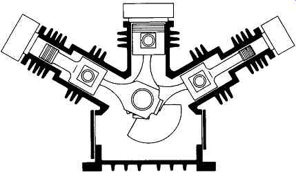
FIG. 11 Stepped cylinder arrangement, air-cooled. (Sulzer-Burckhardt, Winterthur
and Basel Switzerland)
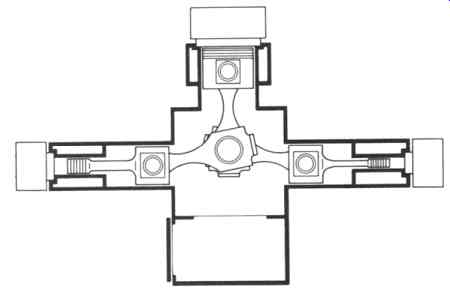
FIG. 12 Stepped cylinder arrangement, water-cooled. (Sulzer-Burckhardt,
Winterthur and Basel Switzerland)
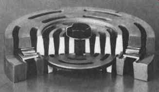
FIG. 13 Typical reciprocating compressor valve combining suction and discharge.
(Sulzer-Burckhardt, Winterthur and Basel, Switzerland)
The design concept represented by FIGs. and 15 allows compressors to be built in up to five stages for discharge pressures up to 5000 psia and suction capacities between 3 and 280 acfm. Up to about 80 kW, these units are air-cooled, and above this limit, they are more often water-cooled.
Compressors of this size are supplied as compact packaged units on a sturdy steel frame. The assembly essentially includes the compressor, motor, V-belt drive, gas coolers, moisture separators, condensate receiving tank, filter, the piping for gas and, where required, for cooling water. The baseplate typically rests on vibration damping elements. The crankshaft is fitted with counterweights to reduce free unbalance forces to an acceptable minimum. Units of this kind are ready for use when placed on a substantial floor or simple foundation and connected to power, suction, and discharge gas lines and, if water cooled, to water lines.
Crosshead-Type Compressors With Cylinder Lubrication
Heavy-duty machines are of the crosshead type with entirely separate and well-controlled cylinder lubrication, water-cooled cylinders, and a relatively low operating speed. Permanently mounted on a good foundation or isolated support system, they can be operated at full load for years with minimum attention.
While the crankcase is lubricated in the usual manner by a forced-feed lubricating pump driven by the crankshaft or by a separate electric motor, a high-pressure lubricating oil pump, also driven by the crankshaft or by a separate electric motor, feeds the cylinders and piston-rod packings. Each high-pressure lubrication element has an adjustable metering device and visual flow control.
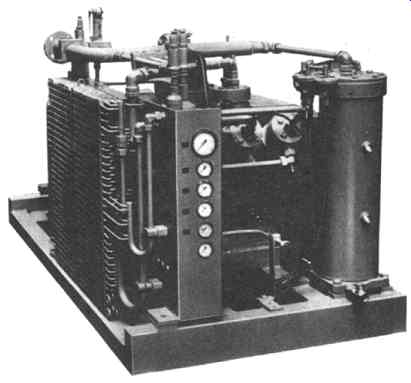
FIG. 14 Air-cooled trunk-piston compressor for 5000psia service. (Sulzer-Burckhardt,
Winterthur and Basel, Switzerland)
FIG. 15 Water-cooled trunk-piston compressor for 4300psia service. (Sulzer-Burckhardt,
Winterthur and Basel, Switzerland)
These machines have a separate crosshead, as shown in FIGs. to 18, with a piston-rod connecting crosshead and piston.
Crosshead-type machines are the most widely used reciprocating compressors in the CPI. Their power input ranges from around 100 to approximately 10,000 kW. As was mentioned earlier, only secondary compressors for the very high pressures needed in the production of LDPE have a higher power input, i.e., up to 15,000 kW. Heavy-duty reciprocating compressors typically use double-acting pistons and perhaps even step pistons for two, three, or even four compression stages on the same piston rod. Thus the gas forces can be equalized very well. The crankcase side of the piston is sealed off by means of piston-rod packing.
With some services, a short single-compartment distance piece is sufficient (FIG. 16), while for flammable, hazardous, or toxic gases, a two-compartment distance piece as shown in FIG. 17 is required.
Since process compressors are often custom-designed for a given duty, standardization, as a rule, is limited to the frame and running gear. There are two basic factors that guide the designer:
1. The maximum power at a given speed that can be transmitted through the shaft and running gear to the pistons.
2. The load imposed on the piston rod, the so-called pin load.
There are other factors involved, for example, the number of cranks, the distance between them, and the piston stroke. These factors represent the working limits for design purposes. Other limits are set by the cylinders, for example, the maximum allowable pressure.
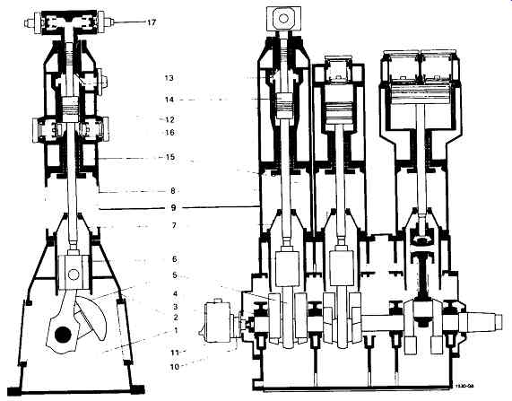
FIG. 16 Vertical, four-stage crosshead-type compressor with cylinder lubrication
and single-compartment distance piece for nontoxic and nonflammable gases.
1 -Crankcase; 2-frame; 3- crankshaft; 4 - bearing; 5 - connecting rod; 6
- crosshead; 7 - cover; 8 - distance piece; 9 - purge chamber; 10 - lubricating
pump for crankcase; 11 - cylinder lubricator; 12 - cylinder; 13 - cylinder
liner; 14 - piston; 15- piston-rod packing; 16- valves; 17-capacity control.
(Sulzer-Burckhardt, Winterthur and Basel, Switzerland)
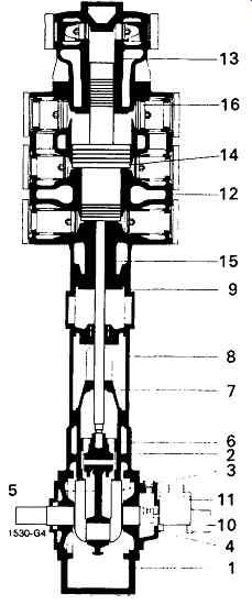
FIG. 17 Vertical, three-stage crosshead-type compressor with cylinder lubrication
and two-compartment distance piece (8 +9) for toxic and/or flammable gases.
Components: 1- Crankcase; 2-frame; 3- crankshaft; 4- bearing; 5- connecting
rod; 6-crosshead; 7 - cover; 8 - distance piece; 9 - purge chamber; 10 - lubricating
pump for crankcase; 11 - cylinder lubricator; 12-cylinder; 13-cylinder liner;
14-piston; 15-piston-rod packing; 16- valves. (Sulzer-Burckhardt, Winterthur
and Basel, Switzerland)
A typical example of a crosshead machine is represented in FIG. 18.
To date, much has been published about the advantages of horizontal versus vertical designs and vice versa. Both designs have their merits, and in some cases, the selection is dictated by the kind of service intended ( FIGs. -19 and 20). It is claimed that a compressor with horizontal opposed cylinders is cheaper to build than one of the vertical type and that it is better balanced. The pipe connections between cylinders and coolers, being closer to floor level, are simpler and easier to support. This type of compressor can be built with an even number of cylinders only, which means that the very popular three-cylinder configuration is not possible. A prominent industry specification, API Standard 618, states that horizontal cylinders are required for handling saturated gases or for gases carrying injected flushing liquids. It also requires that horizontal cylinders have bottom discharge connections. To prevent liquid collecting in the cylinder, arrangements are normally made for delivery valve ports to be on the bottom face of the cylinders, so that liquid is automatically drained by the flow of gas through the cylinder. Horizontal compressors often experience unequal wear on crossheads and their guides, on piston-rod packings, and on piston tings. This may lead to uneven cylinder wear due to force of gravity action in the downward direction.
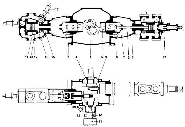
FIG. 18 Horizontal, two-stage crosshead-type compressor with cylinder lubrication.
In addition to unloaders on all suction valves (17), the second stage cylinder
on the right side is fitted with hand-operated clearance pocket control (17).
1 - Crankcase; 2 -frame; 3 - crankshaft; 4 - bearing; 5 - connecting rod;
6 - crosshead; 7 - cover; 8 - packing cartridge; 9 - purge chamber; 10 -
lubricating pump for crankcase; 11 - cylinder lubricator; 12 - cylinder;
13 - cylinder liner; 14 - piston; 15 - piston-rod packing; 16 - valves; 17-
capacity control. (Sulzer-Burckhardt, Winterthur and Basel, Switzerland)
On the other hand, the vertical machine is more compact, requires less floor space, and has shorter interconnecting pipes. Also, with a direct-lifting crane over the machine, assembly and dismantling of cylinders and pistons is facilitated.
FIG. 21 demonstrates that a very compact and space-saving arrangement of compressor, gas coolers, and piping is feasible with horizontal compressors as well. Such an arrangement, however, raises the question of accessibility. With this compressor, the remaining free forces are taken up by the springs on which the unit is mounted. This ensures that only a fraction of the forces is transmitted to the substructure; there is no need for a heavy foundation.
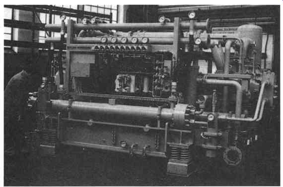
FIG. 19 Compact skid-mounted compressor package with a five-stage compressor
with four horizontal opposed cylinders. Compression is from atmospheric to
2013 psia pressure, capacity is 1820 acfm, and power input is 690 kW at 705
RPM. (Sulzer-Burckhardt, Winterthur and Basel, Switzerland)
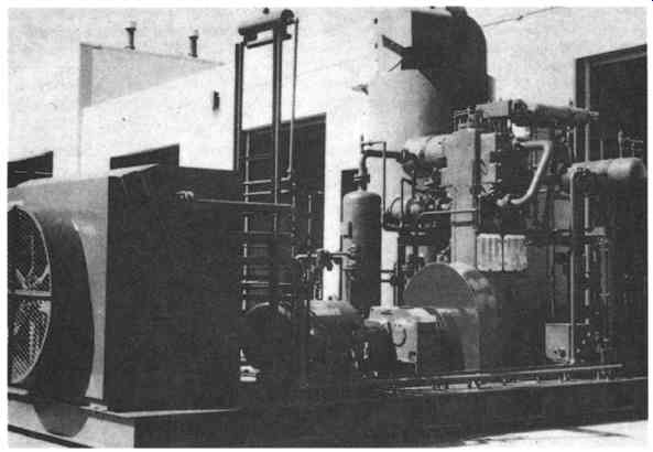
FIG. 20 Vertical, three-stage compressor with a two-crank frame for sour
gas re-injection in an oil field. Compression is from 70 to 2712 psia; the
unit is designed in accordance with API Standard 618. (Sulzer-Burckhardt,
Winterthur and Basel, Switzerland)
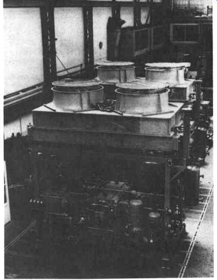
FIG. 21 Three-stage compressor for service on an off-shore platform. Gas
compressed is a hydrocarbon mixture containing hydrogen sulfide. Main data:
1680 acfm, 280 psia, 390 kW. Interstage cooling is by gas-to-air coolers.
(Sulzer-Burckhardt, Winterthur and Basel, Switzerland)
Vertical compressors in atmospheric suction pressure services might have low-pressure cylinders with extremely large diameters. This might make it necessary to lengthen the distance between the cylinder centerlines, and the compressor frame could become too heavy. For atmospheric suction, a horizontal design may thus have advantages over a vertical design, particularly if only two cylinders are required.
Compressors With Water-Lubricated Cylinders
Until compressors with dry-running piston rings, labyrinth-piston compressors, and diaphragm compressors became available, compressors with water-lubricated cylinders were the only oil-free reciprocating compressors on the market. Before 1940, virtually all oxygen compressors were water-lubricated.
Generally speaking, water-lubricated machines are required whenever oil lubrication of the cylinders is not permitted and other oil-free compressors are not economically feasible. This is usually the case if a relatively small quantity of gas has to be compressed to a high pressure.
Three-stage compressors, as shown in FIGs. 22 and 23, are used for suction capacities to roughly 160 acfm and a maximum discharge pressure of about 3600 psia.
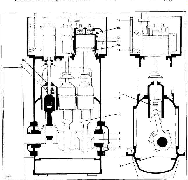
FIG. 22 Section views of a compressor with water-lubricated cylinders. 1-
Crankcase; 2-frame; 3 - crankshaft; 4 - bearing; 5 - connecting rod; 6 -
crosshead; 7- ratchet drive for rotary motion of piston; 8 - cover; 9 - crankcase
lubrication pump; 10 - piston; 11 - cylinder; 12 - cylinder liner; 13 - valves;
14 - gas cooler; 15- cooling-water tank. (Sulzer-Burckhardt, Winterthur and
Basel, Switzerland)
While the beatings of the running gear are lubricated in the conventional manner by means of a crankshaft-driven gear-type oil pump, the cylinders are lubricated with demineralized water. The water passes into the suction pipe at about atmospheric pressure and is carried through all three stages. It is recovered in a separator after the third stage, from where it is returned to the lubrication water tank.
Since the latter is located above the compressor, the water is fed to the suction pipe by gravity. For compressors with elevated suction pressure, the water lubrication system can be pressurized.
The lubrication water tank is equipped with a cloth filter, which prevents solid particles from entering the compressor. Furthermore, it is fitted with a level gauge and a level switch and has connections for the feed, condensate return, and vent lines. A solenoid valve in the feed line is electrically interlocked with the driving motor, whereby the lubrication water circuit is automatically opened or shut off.
A flow indicator with a needle valve allows the flow of lubrication water to be adjusted and regulated. Should the quantity of lubrication water not be sufficient, the drive motor is immediately switched off by means of a monitoring contact.
A ratchet mechanism fitted to each crosshead rotates the piston stepwise at each stroke, thus preventing scoring of the mirror-polished running surfaces of the cylinder liners by the piston packing tings. The latter are made of leather in the first- and of fiber in the second- and third-stage cylinder.
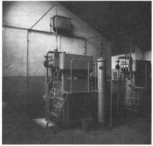
FIG. 23 Three-stage compressor with water-lubricated cylinders. Note the
lubrication-water tank on the wall above the compressor. Main data: Capacity
at maximum speed, 270 RPM- 160 acfm; maximum discharge pressure - 3640 psia;
piston stroke- 250 mm. (Sulzer-Burckhardt, Winterthur and Basel Switzerland)
All cylinders and associated coil-type gas coolers are submerged in a common cooling water tank. This efficient cooling and water lubrication of the piston packings allows compression to take place without any significant temperature rise.
These compressors are extremely well suited for compressing oxygen, hydrogen, helium, nitrogen, air, nitrous oxide gas, etc. The moisture content in the gas leaving a water-lubricated compressor is no higher than in an oil-lubricated or nonlubricated compressor handling humid gas, since the gas is saturated at the outlet of the after-cooler, whether the compressor is water-lubricated or not. If moisture in the gas is not permitted, the water can easily be removed by means of an absorption or refrigeration dryer.
Water-lubricated compressors are low-speed machines. Thanks to their efficient cooling, they allow a relatively high-pressure ratio per stage even in oxygen service.
Like diaphragm compressors, they are very well suited for compressing small quantities of very light gases such as hydrogen and helium to relatively high pressures.
They are, however, less costly than diaphragm compressors. Both hydrogen and helium are particularly "slippery" gases and have a pronounced tendency to slip past the piston tings during compression in a dry-running ring-type compressor and past the labyrinths in a labyrinth-piston-type compressor. This causes low efficiency and high discharge temperatures.
The gas handled by a water-lubricated compressor must be free of dust. Dust causes rapid wear of the cylinder liners and the piston packing rings.
Acetylene Compressors
Among the gases for which specially designed compressors with lubricated cylinders are required, acetylene is a typical example. Acetylene is produced from calcium carbide and water. Under certain temperatures and pressures and also through shock, the gas can decompose violently into its elements hydrogen and carbon. If decomposition occurs in a pressure vessel, the gas can reach a pressure about eleven times that which existed prior to decomposition. The higher the pressure, the smaller the initial force required to cause an explosion. Furthermore, acetylene is highly flammable.
This dangerous propensity is countered by shipping acetylene dissolved in acetone. One volume of acetone dissolves 300 volumes of acetylene at 175 psia.
Acetylene cylinders are partly filled with a porous material that holds the acetone, thus preventing instability of the gas. Full cylinder pressure is 250 psia at 70 degree Most acetylene compressors are used for filling cylinders. In these machines, the explosion hazard must be minimized by other measures. In Europe and other countries, the design of equipment handling acetylene is governed by the Technical Rules for Acetylene Plants and Calcium Carbide Storage (TRAC) rules. These rules, however, do not apply to acetylene compressors used in a chemical process for which other safety rules exist.
Finally, the reader may be interested in reviewing the step-piston construction employed for the acetylene compressor shown in FIG. 24.