AMAZON multi-meters discounts AMAZON oscilloscope discounts
Fan applications in modern process plants range from handling fresh air to moving large volumes of corrosive and abrasive gas streams. This section deals with the fundamentals of selection and operation of fan systems.
Industrial fans can be classified into three basic groups: propeller, axial and centrifugal.
PROPELLER FANS
Propeller fans utilize long slender blades twisted in such a manner as to provide some angle of attack on the gas being moved. The blades are fixed to a hub, and the entire assembly rotates in a housing. The housing has little or no effect on controlling the gas flow.
Typical applications for propeller fans are wall- and ceiling-mounted exhausters (FIG. 1) and cooling tower and air-cooled heat exchangers. Pressures generally range from 0 to 1 inch of water column with efficiencies ranging from 10 percent to 35 percent. Tip speeds are often limited so as to minimize noise generation.
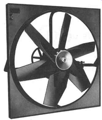
FIG. 1 Wall-mounted exhaust fan (propeller-type). (ACME Engineering & Manufacturing
Co., Muskogee, "OK.)
AXIAL FANS
Axial fans are basically propeller fans with shorter rigid blades assembled in a tubular housing to provide some degree of controlling and/or streamlining the gas flow. FIG. 2 shows a small, simple, single-stage unit, while FIG. 3 depicts a large, heavy-duty industrial version. This type of fan propels gas axially through its housing, which acts as an integral part of the ducting. Axial fans can be further subdivided into two types, namely, vane axial and tube axial. Because of the type of construction employed, these fans lend themselves easily to multistaging if higher pressures are required. FIG. 4 illustrates a two-stage axial fan.
Vane axial fans have vanes installed before and/or after the rotor to direct and streamline the gases for better fan action. The vanes are installed on the stator housing and employ some kind of control mechanism for varying the flow pattern.
Vane axial fans are used primarily in clean gas service, handling pressures generally up to 20 inches of water column (single-staging), but higher pressures are available.
Multistaged vane axial fans can achieve efficiencies in excess of 85 percent and are generally considerably more efficient than tube axial fans.
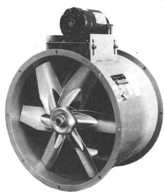
FIG. 2 Small axial fan. (ACME Engineering & Manufacturing Co., Muskogee,
OK.)
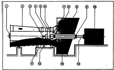
FIG. 3 Heavy-duty single-stage axial fan. 1 - Access door; 2 - diffuser;
3 - external pitch control lever; 4- stationary blades; 5- variable pitch
rotating blades; 6- removable upper fan housing; 7- main bearing assembly;
8 - coupling; 9- inlet box; 10- motor; 11 - blade pitch control mechanism;
12 - rotor assembly; 13 - shaft tube; 14 - drive shaft. (CEMAX Fans, Boston,
MA.)
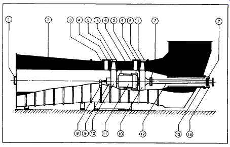
FIG. 4 Heavy-duty two-stage axial fan. 1 - Access door; 2 - diffuser; 3
- removable stationary blade; 4- bolted blade retainers; 5- removable variable
pitch rotating blades; 6 - removable upper fan housing; 7- coupling; 8 -
external pitch control lever; 9 - blade pitch control mechanism; 10- rotor
assembly; 11 - main bearing assembly; 12 - drive shaft; 13 - shaft tube;
14- shaft seal.
Tube axial fans employ the same basic construction as vane axial fans except for the guide vanes and are generally less efficient than vane axial fans. Recently, variable-pitch rotor blade construction has been offered as a standard package for both tube and vane axial fans.
Typical performance characteristics of axial flow fans are shown in FIG. 5.
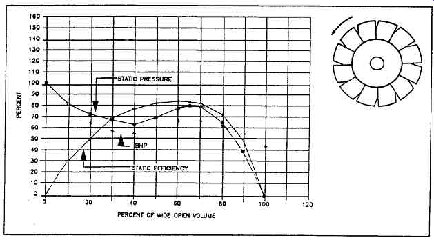
FIG. 5 Axial flow fan characteristics
Note the pronounced "dip," or stall range, in both the static pressure and brake horsepower (BHP) curves. This represents the unstable range in which surge phenomena occur and where fan operation should be avoided. It also explains why axial fans operating in parallel are difficult to start up. Although the absorbed horsepower is initially high, its subsequent decline makes it a non-overloading characteristic.
CENTRIFUGAL FANS
Centrifugal fans (FIG. 6) are prevalent in virtually all of the industry. These fans are applied in building and equipment ventilation, hot-gas recirculation, dust-handling systems, and furnace and boiler forced draft/induced draft services. The basic difference between centrifugal fans and the types previously mentioned is the fact that gas enters the impeller axially and leaves the rotating element radially. The casing is designed and installed around the rotating element to direct the discharge gas in a manner suited for the particular application. Centrifugal fans operate with typical efficiencies in excess of 80 percent and an achievable limit of 91 percent with airfoil blade construction. Discharge pressures can be as high as 90 inches of water column or higher and cover a wide operating range. Centrifugal fans can be categorized by three basic construction styles depending on blade orientation with respect to impeller rotation. These styles are radial blade, backward-inclined blade, and forward-inclined blade. Subtle variations of each style are available.
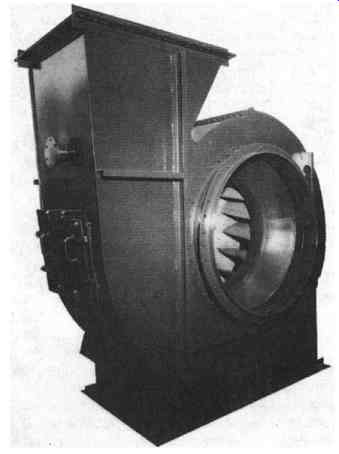
FIG. 6 Centrifugal fan for typical process plant. (ACME Engineering & Manufacturing
Co., Muskogee, OK.)
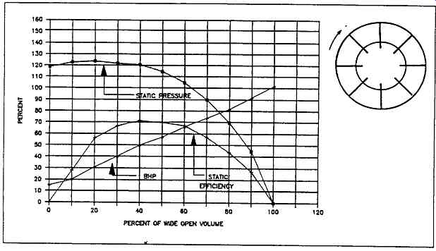
FIG. 7 Radial blade fan characteristics
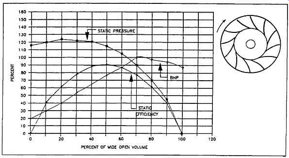
FIG. 8 Radial-tip blade fan performance characteristics
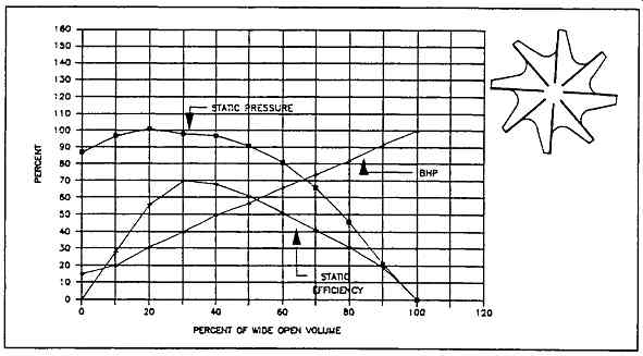
FIG. 9 Open radial blade fan characteristics
Radial Blade
As the name implies, the blades on this type of impeller are radially oriented. This type of impeller construction can be further subdivided into straight radial blade and radial-tip blade styles. The merits of each of these different blades can be observed in Figures 7 through 10. The straight radial bladed fan illustrated in FIG. 7 has a best efficiency of approximately 72 percent. The fan has an overloading horsepower characteristic, but it features stable operation over the entire performance range. Because of low specific speed, straight radial bladed fans have relatively good resistance to abrasion from entrained particles.
The radial-tip fan of FIG. 8 minimizes gas turbulence by curving the blades. It achieves higher efficiencies, with 78 percent to 83 percent being not uncommon. Fan horsepower is non-overloading in the high flow range. This fan also has low specific speed and medium resistance to abrasion.
FIG. 9 illustrates an open radial bladed fan with a geometry that readily allows the addition of simple wear plates for highly abrasive applications. It is lowest in efficiency, with 65 percent being typical. This fan has an overloading power characteristic.
In summary, radial blade fans are commonly used for induced draft service and are especially suited for contaminated gas streams where airborne particles and fouling could be a problem.
Backward-Inclined Blades
The fan blades on this style of rotor are oriented backwards with respect to the direction of rotation. Three variations of backward-inclined blades are available.
Figures 10 through 12 illustrate both geometry and performance of these variations: backward-inclined fiat plates, curved plates, and airfoil blades, with efficiencies increasing in that order. Typical efficiencies for flat plate blades range from 77 percent to 80 percent and 84 percent to 91 percent for airfoil blades. The flat and curved plate blades can handle fine airborne particles that would normally damage the airfoil design. These fans are commonly used in forced draft services.
Modification of the backward-inclined flat plate profile of FIG. 10 reduces the unstable range to moderate instability in the backward-curved blade (FIG. 11) and virtually no instability in the backward-inclined airfoil blade (FIG. 12). Efficiencies show slight increases in the order mentioned; however, the level of tolerance for handling abrasive gas streams decreases as one progresses from backward-inclined to airfoil geometries. All of the backward-inclined blade fans exhibit non-overloading horsepower characteristics.
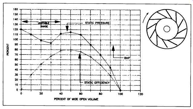
FIG. 10 Backward-inclined blade fan characteristics
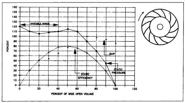
FIG. 11 Backward-curved blade fan characteristics
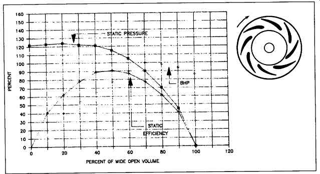
FIG. 12 Backward-inclined airfoil blade fan characteristics
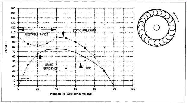
FIG. 13 Forward-curved blade characteristics
===
TABLE 1 Relative Characteristics of Principal Fan Types Centrifugal
Characteristics Backward Vane Radial Vane Forward Lean Axial Propeller
Efficiency High Medium Low High Low Stability of operation Good; Good Fair Good; Good Tip Speed High Medium Low High Medium Noise generation Low High Low Medium; Medium Abrasion resistance Medium Good Low Medium; Medium Tolerance for polymers Medium Good Low Medium Low
===
Forward-Inclined Blades
These fans are styled such that the blades lean forward with respect to the direction of rotation. The two typical variations are the fiat plate and curved plate. FIG. 13 shows geometry and performance of the forward-inclined curved blade style. This type of fan is generally limited to high-volume applications and clean services such as residential heating and air conditioning. Efficiencies range from 72 percent to 76 percent; also, a distinct unstable region exists in the performance curve for this fan type. It has an overloading horsepower characteristic.
A summary of the relative characteristics of the principal fan types is given in TABLE 1.
FAN FUNDAMENTALS
A brief review of commonly accepted definitions will assist us in highlighting the fundamental principles involved in fan selection and operation.
cfm: Volume flow rate expressed in cubic feet per minute at outlet conditions.
SCFM: Volume flow rate expressed in standard cubic feet per minute at a density of 0.075 lb/cu ft.
VP: Velocity pressure is the pressure caused by the average outlet velocity of the gas stream expressed in inches of water column. It is measured in the outlet duct by the differential reading between an impact tube facing the air flow and a static reading normal to the air flow.
SP: Static pressure is that pressure expressed in inches of water column and measured in a manner to exclude the velocity pressure of the gas stream. Static pressure of a fan is the difference in the reading of a Pitot tube placed in the inlet duct and facing in the direction of gas flow and the static reading obtained in the outlet duct. The pressure is usually referenced with respect to 70 degree and a density of 0.075 lb/cu ft.
TP: Total pressure is the algebraic sum of the static pressures and the velocity pressures and is basically the rise from inlet to outlet measured by two impact tubes. It is expressed in inches of water column, much as static pressure.
BHP: The horsepower required to move a specified volume of gas against the indicated static pressure. This is usually referred to air at standard conditions and is sometimes termed air horsepower. Note that for proper sizing of the driver, this should be calculated with respect to total pressure rather than static pressure and should include the ratio of actual density/air density at standard conditions.
62.3 x SP x cfm BHP = 12 x 33,000 x SE
ME" Mechanical efficiency is the ratio of the horsepower delivered to the input horsepower.
SE: Static efficiency is the mechanical efficiency multiplied by the ratio of static pressure to total pressure.
SE- ME x (SP)/(TP) SND: Static no delivery or zero flow.
WOV: Wide open volume (zero static pressure). OV: Outlet velocity, cfm/outlet area.
Gas density - lb/cu ft x (average outlet velocity - ft/min) 2 VP: = 1.203 x 10E6 Note for standard conditions, the density of air - 0.075 lb/cu ft. The unit of pressure is expressed in inches of water column where the density of water is specified as 62.3 lb/cu ft.
Specific Speed: The speed in RPM at which a fan would operate if reduced proportionally in size to deliver 1 cu ft/min against a static pressure of one inch of water.
0 75 RPM x cfm ~ x (gas density/0.075) 9
Specific speed = Sp0.75
Fans are governed by certain basic laws known as the fan laws. These laws are reasonably accurate and can be stated as follows: For variation in speed:
1. The volume delivered is proportional to the speed.
2. The static pressure across a fan is proportional to the square of the speed.
3. Brake horsepower is proportional to the cube of the speed.
For variation in size:
1. Volume is proportional to the cube of the wheel diameter.
2. Static pressure is proportional to the square of the wheel diameter.
3. Brake horsepower is proportional to the fifth power of the wheel diameter.
If both fan size and speed are changed, then the combination factors should be calculated.
FAN PERFORMANCE AND SYSTEM EFFECTS
The performance of the centrifugal fan is represented by either a multi-rating capacity table indicating various points on a family of constant speed performance curves or by a single graph developed by plotting at a fixed speed the static pressure (SP) in inches of water column versus volume flow (cfm) expressed in cubic feet per minute.
The fan develops pressure for various volumes of air flow through it and the proposed system. The characteristic fan performance curves shown earlier are constant speed (RPM) performance curves for operation from wide open volume position (zero static pressure, maximum volume) to static-no-delivery position (zero volume). Each performance curve is plotted for a specific RPM and fan size as well as a fixed air or gas density.
A simple system might consist of ductwork connected to either the fan inlet, discharge, or both, in addition to elbows, dust collectors, scrubbers, furnaces, etc., through which air may be forced to flow. The prime mover, of course, is the fan or blower in the duct system, which provides the energy to the airstream to overcome the resistance to flow of its various components. Each fan and blower system is unique, i.e., they have a combined system resistance to a specific flow that varies from system to system and is dependent on the resistance to air flow for each individual component of the system. In a fixed system, the volume flow rate (cfm) will have a corresponding pressure loss (system resistance), generally expressed as static pressure, the resistance to the flow varying directly as the square of the increased or decreased flow rate. The equation defining the relationship between flow and pressure drop in a fixed system is as follows:
(cfm-final/cfm-original) 2 = (SP-final/SP-original)
FIG. 14 represents a fixed system resistance curve to air flow and is calculated as a parabolic equation relating flow to pressure as shown in the above expression. If the actual resistance curve is substantially different from the calculated one, the performance will, of course, deviate, and in extreme cases, it will risk operation in the unstable zone.
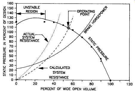
FIG. 14 Effect of system resistance on fan performance.
Just as different designs of fans have different characteristic performance curves, different types of systems have different characteristic resistance curves.
The more complex the system, the more involved the characteristic curve. However, the complex systems can be separated into their component parts, the individual characteristics of which are known, and a summation of the resistance of several components of a system will give the composite resistance of the overall system.
The terminology resistance to flow is generally accepted as equivalent to the phrase pressure loss for the individual system. The determination of pressure loss may be accomplished by use of handbook values for loss through ducting and branch piping as well as by published or computed values for resistance to flow through the individual pieces or components of the system. It is important to remember that the resistance for the system should be expressed in terms of standard air defined as 0.075 lb/cu ft density. The latter resistance may then be related to fan static pressure requirements that are read directly from fan manufacturers' published performance data based on standard air with a density of 0.075 lb/cu ft.
The Air Moving and Control Association (AMCA) has long been aware of the problem in applying fans in systems where inlet and outlet conditions vary from test facilities. The association is publishing a manual indicating guidelines or factors to be used in computing fan static pressure requirements when inlet and outlet connections are less than the desired design. Frequently, the system designer will add a factor of safety to his or her calculations of the system resistance in an attempt to adjust for inaccurate evaluations or to compensate for poor inlet or outlet connections. These safety factors rarely compensate for the "system effect" on the fan performance, and it is necessary either to make adjustments in the system by improving inlet and/or outlet conditions or by increasing the fan speed to obtain the desired fan capacity. However, it will be necessary to establish whether or not the increased fan speed is within the structural limits of the equipment before deciding to increase the speed of the fan. Obviously, poor inlet and outlet conditions should be corrected in order to keep operating horsepower and cost to a minimum.
A few of the most common conditions that result in deficient performance of the fan include (1) prerotation of the air into the fan inlet due to a vortex condition that occurs when the fan inlet is placed too close to an obstruction or wall, (2) nonuniform flow due to elbows prior to fan inlet, and (3) omission of an outlet duct on the fan discharge. These conditions will definitely alter the characteristic of the fan performance so that its full volume flow potential is not realized. This system effect in the performance of the fan and blower must be considered in the evaluation of the pressure loss for the total system.
If the application engineer or system designer has accurately determined the resistance to flow through a given system, the fan engineer will be in a position to properly evaluate and select the fan that will develop the required flow and pressure to meet system requirements. When placed into a system, the fan will operate only where its characteristic performance curve intersects the actual system resistance curve. FIG. 14 shows the fan characteristic performance curve with the calculated system resistance curve superimposed and the resultant point of intersection that should be the design operating point-(55 percent of wide open volume and 107 percent of design pressure). If the system resistance has been accurately determined and the fan properly applied, the design performance will be at the intersection of the two curves. When the pressure losses have not been accurately determined for the system, the intersection of the fan performance curve and the actual system curve will not coincide with the design point. Occasionally, fans operating in a position other than design point may be subject to unstable or pulsating flow, which may damage the fan and the system components.
Should the estimate of a system resistance be less than actually required for the flow rate, the resultant flow will be less than required. This is also illustrated in FIG. 14. When the actual system resistance is less than the calculated value, the flow will be higher than the design flow rate and will require additional horsepower to drive that particular fan.
Frequently, in the case of direct-connected fans, the design flow and calculated resistance of the system will not fall exactly on the constant speed fan performance curve. In this particular situation, the fan will deliver more or less air, depending on where the system curve intersects the fan curve, and adjustments will be necessary to obtain the required performance. The adjustments may involve the use of a damper to throttle the flow to design requirements or to reduce the speed of the fan until the required flow is achieved. Should the system resistance curve intersect the fan curve at a lower value than design flow, it will be necessary either to reduce the resistance by the use of turning vanes or splitters in the duct elbows, etc., or to speed the fan up to achieve the design flow requirements. This topic will be addressed later.
The foregoing comments and figures are based on fan inlet and outlet connections in accordance with good design practice as applied in actual laboratory tests.
When fan inlet or outlet conditions vary from good design practice, design performance may not be obtained even though the system resistance has been properly calculated.
The system effect on fan performance is dependent on the type of inlet or outlet condition as well as gas properties and velocity. The system effect, therefore, will not be uniform throughout the complete range of the fan performance curve.
===
TABLE 2 Air Density Ratios of Various Altitudes and Air Temperatures* Altitude in Feet above Sea Level
===
Performance Corrections
When the fan will be handling a gas at a density other than standard (0.075 lb/cu ft), it may be necessary to use correction factors so that the published tables may be used accurately. Frequently, fan operating specifications are given at temperature, altitude, and/or air density other than standard conditions. The AMCA publishes standards and rating tables for fan equipment. Since fans will operate only where the system resistance curve intersects the fan performance curve, it is important to make certain the fan performance and system resistance are compared on the same basis, i.e., values shown in the same basic units at identical operating conditions.
Example 1: Temperature and Altitude Required: A fan to exhaust 10,000 cfm of 650 ~ air at a static pressure (system resistance) of 4.0 inches at 650 ~ and at an elevation of 2000 feet.
Step 1. The volume of air will be 10,000 cfm at 650 ~ and since no reference is made to weight, this value is correct for selection directly from fan rating tables.
Step 2. Static pressure is specified at 650 ~ and 2000 ft elevation. Therefore, it will be necessary to correct this value in order to make use of the performance tables.
Step 3. The density ratio obtained from TABLE 2 for gas density at 650~ and 2000 ft elevation show 0.444. To obtain 4.0 inches SP at 650~ we must select a fan at the adjusted static pressure from the standard tables determined as follows:
where SPc = static pressure at site conditions
SPs = static pressure at standard conditions(70 degree and 0.075 lb/cu ft density)
Pc = density of gas at site conditions
Ps = density of gas at standard conditions
P' = density ratio Pc/Ps (see TABLE 2)
Select a fan from the manufacturer's published rating tables for 10,000 cfm and static pressure, SP, of 9.0 inches of water column. In selecting the fan from the manufacturer's tables, let us assume we read 1832 RPM and 16.0 BHP.
Restating the performance at standard conditions for the selected fan size and type: 10,000 cfm, SP = 9.0 inches, 1832 RPM, 16.0 BHP (standard conditions) .... Step 4. Now check performance when handling air at the actual operating conditions. Referring to the fan laws for variations in air density:
cfm: unchanged - 10,000 cfm RPM: unchanged- 1832 RPM SPc = SPs • P' = 9.0 • 0.444 - 4.0 in BHP = BHP x P' = 16.0 • 0.444 -- 7.1
...where: BHPc = brake horsepower at site conditions B HPs = brake horsepower at standard conditions We have a choice of sizing the motor to drive the fan at start-up (ambient conditions 70 degree with a 20-HP motor or using a damper and/or a speed control device so as to reduce the motor size to the amount required under operating conditions (7.1 BHP) or a 7.5-HP motor.
Example 2: SCFM- Temperature Correction
Select a fan to move 20,000 SCFM at 400 degree against a static pressure of 2.0 inches at 400 degree and sea level:
Step 1. Since specifications indicate there will be a requirement for weight flow at 400 degree it is necessary to correct the SCFM specified to a yield cfm at 400 degree delivering the same weight. If the SCFM did not indicate a temperature, it would be necessary to either question the specifications or to assume that the SCFM was at 70 degree.
Here are the corrections:
Step 2. cfm = (SCFM) Ps/Pc = 20,000 x 1/0.616 = 32,500 cfm and correction of static pressure
SPs = SPc 1/P' = 2.0 x 1/0.616 - 3.25 in
The fan unit would have to be selected from the manufacturer's rating tables for 32,500 cfm, 3.25 inches SP. Assuming the selected fan unit requires 700 RPM and 20.0 B HP, at standard conditions, we would determine the horsepower consumed at the actual operating conditions by multiplying by the density ratio factor:
Step 3. HPc = HPs x P' = 20.0 x 0.616- 12.32 HP at actual conditions
Example 3: Wheel Diameter Correction
We require increased pressure and volume capability, but we are unable to increase the speed. FIG. 15 illustrates the performance curve of an available 40-inch diameter centrifugal fan operating at 1000 RPM. TABLE 3 shows a functional data form listing operating points taken from the 40-inch diameter fan performance curve of FIG. 15 and calculated data for plotting the 45 1/8-inch diameter fan performance curve at the same speed. The 40-inch diameter fan curve has been divided into several sections as indicated by a series of conveniently selected points on both the curve and left portion of TABLE 3.
Fan Law Factors
45.125 in
Wheel diameter factor = = 1.129 40.000 in
Flow factor = (1.129)3 _ 1.44
Pressure factor = (1.129)2 = 1.275
Horsepower factor = (1.129) 5 = 1.836
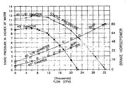
FIG. 15 Constant speed diameter performance curves for different diameter
fans
TABLE 3 Fan Performance at a Series of Operating Points: Point CFM SP BHP CFM SP BHP
From TABLE 3, we take Point "F" as a sample for applying the calculated fan law factors.
point cfm SP BHP cfm SP BHP
F 14,000 6.7 30 20,160 8.54 55.00
cfm = 1.44 x 14,000 = 20,160
SP = 1.275 x 6.7 = 8.54
BHP = 1.836 x 30 = 55.00
The 45 1/8-inch diameter fan performance curve at 1000 RPM has similar characteristics as the 40-inch diameter curve. In rating performance from one size fan to another, the rating process should always be accomplished from a base curve of the smaller fan.
Example 4: Speed Variation
A 30-inch radial bladed centrifugal fan handling 3000 cfm of clean air against a system resistance of 15.75 inch water column absorbs 12 BHP when running at ...
1780 RPM. For an uprated volume of 4000 cfm of air, the new speed, BHP and pressure would be calculated as follows:
Original Volume / New Volume = Original speed / New Speed
CAPACITY CONTROL OF FANS
Centrifugal Fans
Control of the output capacity of a centrifugal fan is accomplished by adjusting either the fan characteristics or the system characteristics. Fan characteristics may be modified by changing the rotation or speed of the wheel or by altering the rotation or whirl of the inlet air. System characteristics may be altered by either increasing or decreasing resistance somewhere in the system.
A number of methods of capacity control are used in current practice. The relative importance assigned to various factors of the particular application governs the choice of method. Basically, the primary design function is to achieve maximum efficiency through control or maximum reduction in operating power to accompany the required reduction in capacity. Selection of a method of capacity control will result from evaluation of such factors as initial cost, operating costs, range of control required, speed of response, simplicity of operation, auxiliary controls, reliability, longevity, maintenance, etc.
The effects of the three primary methods of control (inlet vane control, discharge damper control, and speed control) in relation to fan performance are illustrated on the constant speed curves shown in FIGs. through 18. The curves are identical in speed, and the performance characteristics are arbitrarily based on the non-overloading airfoil-type fan.
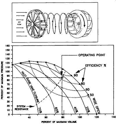
FIG. 16 Performance curves for inlet vane control at constant speed
Inlet Vane Control
Inlet vane control consists of a number of vanes or blades located at the inlet to the fan. The varies may be adjusted to various positions so that the entering air is given a change in direction or a spin in the direction of wheel rotation as illustrated in FIG. 16.
The initial spin modifies the basic characteristics of pressure output and power input, resulting in a new and reduced pressure and horsepower characteristic. This is graphically illustrated in the differential between the base curve and percent inlet guide vane closure curves shown in FIG. 16. Adjustment of the vanes to various positions, thereby changing the extent of the initial spin, gives regulation to any required volumetric flow at only the pressure demanded by the system. A spin in either direction will reduce the capacity of the fan. A spin contrary to wheel rotation will often increase the shaft horsepower. A spin in the same direction as wheel rotation, as shown, will reduce shaft horsepower. With inlet guide vane control, the fan performance curve is repositioned as the vanes are moved from the wide open to the closed position, with the system resistance curve staying effectively the same.
Inlet vane control provides moderate first cost, excellent operating costs, wide-range regulation, simplicity in operation and auxiliary controls, low maintenance, and relatively long life. Of course, the vane structure must be sufficiently rigid to withstand significant aerodynamic forces, and the mechanism for moving the vanes should be such that all are positioned equally, with considerable degree of accuracy.
Inlet vane control mechanisms are limited to use in relatively low temperature applications (up to 900 degree and may have limited life in abrasive and/or corrosive atmospheres.
It is often believed that inlet guide vane control acts like a multiple-leaf damper.
This is quite wrong. A damper is independent of the fan and is not intended to affect fan performance in any way, although if a damper is located near the fan suction, it may do so to the detriment of fan performance. A damper is merely an adjustable resistance in the system intended to waste horsepower. Vane control, on the other hand, acts primarily to modify the fan performance so as to reduce the power required to attain a specific set of conditions. Such resistance as the inlet vane controller interposes is incidental and has no effect on its principal function of fan performance modification.
Damper Control
Parallel Vane Operation; Opposed Vane Operation
A damper consists of one or more pivoted blades acting as a valve in the duct whereby resistance to flow may be varied from wide open to virtually blocked tight.
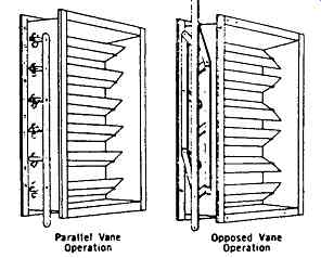
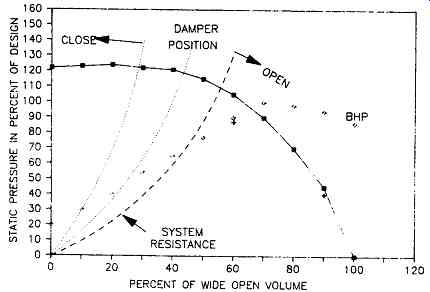
FIG. 17 Effect of damper control on system characteristics
FIG. 17 illustrates the change in system characteristics achieved with damper control. The same figure also shows two different arrangements of the commonly used multivane damper normally mounted on the fan discharge or in the duct system downstream of the fan. Each of these arrangements has individual characteristics as to its effect on airflow; but, in general, both provide a variable resistance for the system.
The multiple vane damper, often called a louver damper, should be considered as an independent element interposed between the fan and the system. As previously mentioned, the system characteristics and not the fan characteristics are affected by the damper.
As shown in FIG. 17, when the system resistance is altered, the operating point on the fan curve is shifted correspondingly. At reduced volume, the fan develops a higher pressure than the system requires. The curve is shifted to the left as the damper is moved from the wide open to the closed position, with the fan performance curve staying effectively the same.
A damper in a duct system controls the flow and dissipates energy by warming the flowing air. A considerable amount of the power input to the fan is converted by warming the air just slightly. Nevertheless, something must be done to control air flow, and the damper is often the most desirable method, even at the expense of wasted horsepower.
The damper method of control provides minimal initial cost, moderate operating costs, wide-range regulation, simplicity of operation, and relatively long life.
Dampers can be fabricated to withstand extremes in temperature and are capable of satisfactory operation in abrasive and/or corrosive atmospheres. Within design limitations, damper construction can be provided for gas-tight and insulated applications.
Speed Control
When a fan is controlled by varying its speed, there is no waste. At each volume, the fan develops a pressure just equal to the system resistance and no more. From the stand-point of the fan, variable speed control is most economically attained.
Variable speed control is predicated on the theory that the volume of air flowing is proportional to the fan speed; the pressure developed is proportional to the square of the speed; and the horsepower is proportional to the cube of the speed. Therefore, from a given constant speed performance curve, new curves at other speeds can be easily computed.
On reviewing FIG. 18, it becomes obvious that each fan speed gives a complete and separate performance curve. Since the system resistance has not been physically altered, each reduction in fan speed will provide a new fan performance curve crossing the system resistance curve below the base curve, as illustrated. In like manner, fan speeds in excess of base curve speeds provide performance curves that cross the system resistance curve above the base curve.
Many methods of providing variable speed drives are available, each having its own specific desirable and undesirable features. Basically, variable speed control is accomplished by one of two methods: a variable speed prime mover connected directly to the fan shaft; or a constant speed prime mover with interconnecting adjustable means to vary the fan speed.
The turbine, direct current (DC) motor and variable frequency alternating current (AC) motor drive fall within the variable speed prime mover classification and may be considered as completely variable. The slip-ring AC motor and the two- and three-speed AC motors also fall within this classification but should be considered as semivariable and stepped.
The hydraulic and electrical coupling and the variable pitch drive are interconnecting adjustable mechanisms for variation of fan speed. For small fans, the variable pitch sheave and belt drive arrangement is by far the most popular today.
Large fans are generally not equipped with belt drives.
The ultimate decision as to which control method or methods to use depends on the functional overall system requirements. Comparisons must also take into account differences in first cost, fixed charges, maintenance cost, use factor, environmental conditions, power demands, stability, etc.
A combination of two methods of control, such as a two-speed drive with vane control, will frequently provide the most suitable as well as the most economical method of controlling the fan. Also, a variable speed drive and a multivane damper can be combined to permit utilization of a much smaller motor in elevated temperature systems.
To ensure proper capacity control of a centrifugal fan, knowledge of the effects of each of the methods described above will be helpful. FIG. 19 graphically compares the three basic methods.
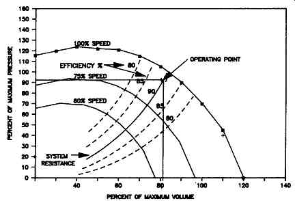
FIG. 18 Variable speed performance curves
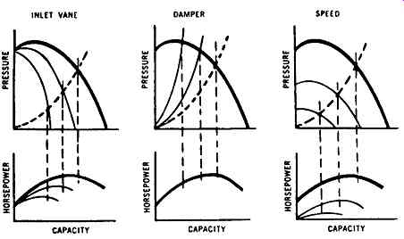
FIG. 19 Comparison of various fan control methods.
Axial Fan Control
Although all of the previously mentioned control methods could be used, axial fan control is most often accomplished by adjusting the blade angle. This adjustment can normally be accomplished with the fan either shut down or in operation, and both pneumatic and hydraulic actuating mechanisms are available.
The pitch of all blades is changed simultaneously, and the actuating signal can be manual or automatic. Axial fan blade pitch controls have been configured to respond to changes in gas velocity, temperature, pressure, gas composition, and other parameters.
Blade angle adjustment allows efficiencies to be optimized under a wide range of pressure and flow conditions. Operation in the stall region of the performance curve can be effectively avoided by this highly flexible control method, which is shown in FIG. 20.
Fan Control Summary
Centrifugal fans can be controlled by the following:
++Movable inlet guide vanes that vary the pre-rotation angle of the incoming gas.
The resulting change produces a shift in the performance curve, which now intersects with the system resistance curve at different pressures and flows, bringing about a different power requirement.
++Dampers, which throttle the flow either at the fan inlet or outlet and thus cause a shift in the system resistance curve. This shift results in a new point of intersection with the performance curve, and a new pressure-flow relationship is established.
Damper control is both less efficient and lower in initial cost than movable inlet guide vane control.
++Speed changes that produce a parallel shift of the performance curves, which will now intersect the system resistance curve at different pressures and flows. This control method is more energy-efficient than either inlet guide vane or damper controls.
Axial fans can be most efficiently controlled by varying the blade pitch angle.
Speed, damper, or stationary blade pitch angle controls are feasible, but they are usually less economically attractive.
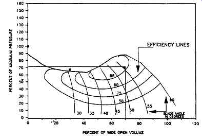
FIG. 20 Axial flow fan performance with variable pitch blade control