Design Features
++Robust design with cast casing and separate blade carrier
++Casing supported by means of pendulum supports (minimum expansion forces) or feet with keyways for the smaller frame sizes
++Solid or hollow rotors, very smooth running characteristics with integrated balancing pistons
++Blading with optimal aerodynamic characteristics--with high efficiency, large specific capacity, low stressing, favorable control characteristics
++Great safety against blade vibrations thanks to the careful selection of the blade profiles and the special blade fixation
++Adjustable stator blades - of standard design - for optimum flow control
++Maintenance-free, oil-free stator blade adjusting mechanism which is also protected against the ingress of contaminants
++Possibility of fitting various types of bearings
++Possibility of fitting various shaft seals
TABLE 2 Selection and performance calculation of an axial compressor ; calculation example Air compressor, type A
Casings, Bearing Pedestals
Depending on the type of gas and the design pressure, the casings are made of grey cast iron, nodular cast iron or cast steel. The cast design facilitates a rigid construction, effective noise attenuation and aerodynamically favorable layout of the respective ducting. The suction and delivery branches are usually routed vertically downwards. In cases where, due to the composition of the gas and/or the pressure level, steel casings are mandatory, a welded construction can be supplied. The suction branch may then be axial, or both suction and discharge may be routed upwards or downwards. In the vertical central plane, the casing is aligned by two keyways; it is equipped with four supporting feet. It is fixed at one end in the axial direction by one pair of feet. The other pair of feet of large frame sizes rests on pendulum supports with spherical contact surfaces. As a result of this, the casing can take up the thermal expansion in both the axial and lateral direction without difficulty. This feature is particularly advantageous in the case of light steel foundations. On small frame sizes the pendulum supports are replaced by sliding keyways.
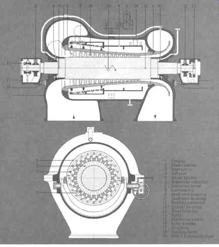
FIG. 14 Longitudinal and cross-sectional view of an A V compressor. (Sulzer
Turbo Ltd., Zurich , Switzerland )
Blade Carrier, Casing Inserts
The blade carder inserted in the casing is centered on both the suction and discharge side, and is able to expand freely in the axial direction. The diffusor and the gland inserts are also fitted as separate parts in the casing.
The double-casing design with outer casing and blade carder offers various advantages:
++Rigid casing construction; the clearances in the blade duct are not influenced directly by external pipe forces.
++Simple fitting of the blades and assembly of the casing parts; the top half of the casing can be raised without dismantling the blade-adjusting mechanism.
++Possibility of fitting different blade carriers, for adapting the blade duct and thus the compressor characteristics to greatly changed operating conditions.
++Optimal protection of the adjusting mechanism in the space between the casing and blade carder; the space is kept under suction pressure in order to safeguard the adjusting mechanism against condensation and corrosion attack.
Rotor
The rotors are usually of forged solid design. In the case of larger machines or if the moment of inertia must be minimized to limit the power requirement when running up with an electric motor, welded hollow rotors may be used. Integrated balancing pistons at both ends of the rotor facilitate an equalization of the axial thrust. The careful balancing of the rotor at full speed results in highly smooth running characteristics. If necessary, balancing can also be effected in the casing.
The labyrinth strips are caulked in the rotor.
Blading
Blading with a high degree of reaction, i.e. the increase in pressure takes place exclusively in the rotating components, is employed for the compression of lighter gases such as helium or hydrogen. (See Figures 12-15.) For all other applications, such as the compression of air, blading with a lower percentage reaction is adopted. The increase in pressure is distributed to the rotor and stator blades. This enables the following major advantages to be realized:
++Higher efficiency with lower aerodynamic loading
++Widest possible control range with high part-load efficiency at constant speed
++Largest possible suction volume at given speed
++Increased reliability of operation thanks to larger radial blade clearances and the omission of guide vane sealings
++Steeper pressure volume characteristics, especially suitable for capacity control, for the parallel operation of different compressors, for refrigeration processes and for exact adjustment of the blow-off line.
The rotor and stator blades are normally made of 13% chrome steel and machined. When handling highly contaminated aggressive air or corrosive gases, alloys with higher chromium and nickel content may be used. The rotor blades have rhomboidal roots and are firmly braced in an exactly defined position in the peripheral grooves of the rotor. This is of particular importance for their vibration-related design. The fixed stator blades are provided with a rectangular foot. The adjustable stator blades are made in one piece with a cylindrical shaft. The latter is seated in a beating bush in the blade cartier. The high damping characteristics of this seating arrangement practically excludes the occurrence of dangerous vibration amplitudes associated with the stator blades.
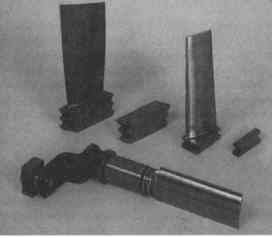
FIG. 15 Adjustable stator blade, rotor blade and fixed stator blade with
intermediate piece. (Sulzer Turbo Ltd., Zurich , Switzerland )
Stator Blade Adjusting Mechanism for the AV types
The adjusting mechanism is located in an annular space between casing and blade carrier, and is thus well protected against contaminants and moisture. It is maintenance-free and does not require any lubrication.
Servomotors. Two types of servomotors are available (see Figures 16 and 17): Automatic mass flow, volume or pressure control. The adjusting mechanism is operated by means of two hydraulic servomotors which are affixed laterally to the casing. One of the servomotors is equipped with a positioning transmitter and the second operates hydraulically in parallel.
The linear movement of the servomotor piston rods is transmitted directly to the adjusting cylinder by way of two ball and socket joints.
Remote setting of reference value. One single electric servomotor is attached laterally to the bottom half of the casing. Its driving shaft actuates a pivoted fork positioned on either side of the casing in maintenance-free beatings. This fork in turn moves the adjusting cylinder in axial direction.
Adjusting cylinder. The adjusting cylinder of welded design can move in the axial direction and is dry-seated. There is no restriction of heat expansion in any direction.
U-shaped guide tings are provided on the inner side in which the adjusting levers are engaged.
Stator blades. The adjusting levers provided on the end of each stator blade shaft are connected to the guide tings of the adjusting cylinder by means of pivoting sliders. The axial movement of the cylinder is converted into a rotating movement of the stator blades (see FIG. 18).
The self-lubricating bearing bushes of the blade shafts are seated in the radial holes of the blade carrier. O-ring packings prevent the ingress of contaminants into the stator blade seating.
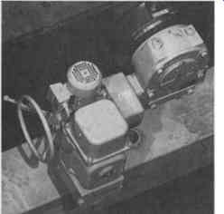
FIG. 16 Electric servomotor. (Sulzer Turbo Ltd., Zurich , Switzerland )
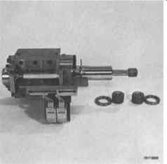
FIG. 17 Hydraulic servomotor. (Sulzer Turbo Ltd., Zurich , Switzerland )
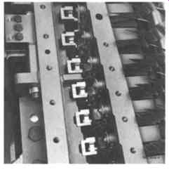
FIG. 18 Stator blade adjusting mechanism. (Sulzer Turbo Ltd., Zurich , Switzerland
)
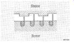
FIG. 19 Labyrinth shaft seals. (Sulzer Turbo Ltd., Zurich , Switzerland
)
Shaft Seals
Labyrinth seals (FIG. 19) are used for the standard models. The stainless steel labyrinth strips are caulked on the rotor and are easily replaceable. In case of rubbing due to unbalance, the friction-induced heat is immediately passed to the massive stator, thus avoiding distortion of the rotor. Gas-tight shaft seals and standstill seals can be fitted for special requirements.
Journal and Axial Bearings
Journal bearings. In the normal version, i.e. with the compressor rotor solidly coupled and the rotor thrust transferred to the axial thrust bearing of the prime mover or the gear, the bearing housings are equipped only with journal beatings. Two-lobe bearings are provided for the lower speed range; tilting pad journal bearings (FIG. 20) being generally used for the higher speeds of the smaller frame sizes for reasons of stability. The slight curvature of the adjusting plates allows the bearings to be set accurately on erection. The bearings (FIG. 21) are firmly held in position by the bearing housing top half. Two-lobe bearings are suitable for both senses of rotation, while tilting pad bearings are essentially for only one direction, although they can tolerate running backwards with a somewhat reduced load capacity.
Axial thrust bearings. If a flexible coupling is selected between driver and driven machine, the bearing housing can accommodate the necessary tilting pad thrust bearing. The purpose of this beating is to absorb the remaining thrust of the machine and any significant axial friction thrust of the coupling due to sharp temporary differential expansion between rotor and casing. To provide easy access and reduce the overhang, it is preferably mounted on the free shaft end.
The tilting pads are supported on load equalizing segments which allow angularity of the shaft of up to 0.3%. Because the tilting pads are supported eccentrically, thrust bearings are suitable for only one direction, but tolerate a reversed rotation at a somewhat reduced load capacity. FIG. 22 shows a popular thrust bearing.
TABLE 3 Material Table, Valid for Air and Similar Gases Machine component Material DIN No. ASTM No.
Solid coupling
It is Sulzer's normal practice to make extensive use of solid couplings allowing the use of only one axial thrust bearing for single- or multiple-casing arrangements.
An intermediate shaft, flexible enough to allow for considerable misalignment, is inserted between the two shaft ends of the machines to be coupled together (FIG. 23). In case of motor-driven units, the normal technique is to use single helical gears provided with thrust collars on the pinion shaft, as shown in FIG. 24 and 25. The thrust collars not only neutralize the axial thrust created by the meshing of the teeth cut at an angle to the axis of the shaft, but also transmit the unbalanced axial thrust of the high-speed rotor train to the thrust bearing on the low-speed wheel shaft.
Good gear meshing requires parallelity of gear and pinion shaft and automatically assures parallelity of the contact surfaces of thrust collar and wheel rim. The slight tapering of the thrust collars is responsible for the formation of a wedge-type oil film creating a pressure zone spread out on an enlarged surface with a pressure distribution very similar to that of a standard-oil-lubricated journal bearing.
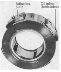
FIG. 20 Multi-segment journal bearing with four tilting pads. (Sulzer Turbo
Ltd., Zurich , Switzerland )
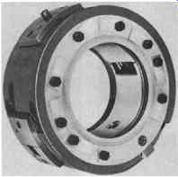
FIG. 21 Two-lobe journal bearing. (Sulzer Turbo Ltd., Zurich , Switzerland
)
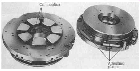
FIG. 22 Kingsbury-type thrust bearing with self-equalizing pads with directed
lubrication. (Sulzer Turbo Ltd., Zurich , Switzerland )
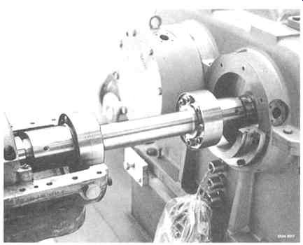
FIG. 23 The Sulzer solid quill-shaft coupling conforms to API 671 standard
and consists of the quill shaft and the two hubs hydraulically fitted onto
the shaft ends of the connected machines. On each coupling side, an equal
number of tie bolts for axial fixation and tapered dowel pins for torque transmission
and centering assure a clearly defined connection. Balancing as a complete
assembled unit and correlative marking enable removal and remounting of this
intermediate shaft with the connected rotors remaining in place, without affecting
the balancing quality and vibration behavior of the complete string. (Sulzer
Turbo Ltd., Zurich , Switzerland )
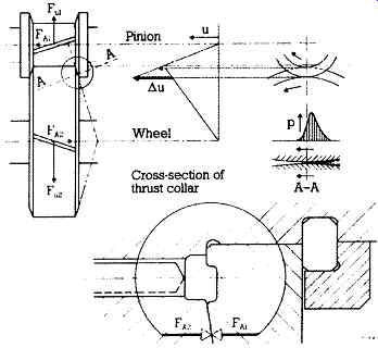
FIG. 24 Method of axial thrust transfer in a single helical gear with thrust
collar. (Sulzer Turbo Ltd., Zurich , Switzerland )
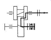
FIG. 25 Transfer of external forces. (Sulzer Turbo Ltd., Zurich, Switzerland)
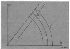
FIG. 26 Characteristics of a turbocompressor p- Discharge pressure; V- Flow
rate; C-Compressor characteristic curves; S- Surge line; L- Limit flow (Sulzer
Turbo Ltd., Zurich , Switzerland )
The relative motion between the two contact surfaces of the thrust collar system is a combination of rolling and sliding and takes place near the pitch circle diameter, resulting in a very small relative velocity. The thrust transmission is therefore effected with almost no mechanical losses. The considerably reduced losses of the single thrust bearing on the low-speed shaft as compared with the high losses of individual thrust bearings on the high-speed train lead to a substantial power saving.
Moreover, this low-speed bearing can be more amply dimensioned to provide a much higher overload capacity.
For direct turbine-driven compressor trains, the thrust bearing is usually located in the turbine. Also in this case solid couplings with flexible intermediate shafts are much preferred.
This coupling arrangement avoids heavy overhung gear couplings which are usually responsible for not clearly defined lower critical speeds and for the phenomena of torque lock leading to additional loading of the axial thrust beating.
The resulting axial friction forces can become quite substantial if insufficient attention is given to the cleanliness of the lubricating oil.
Safety Systems and Process Control
Two main requirements are to be met by the control system of turbo-compressors.
++Safety: to prevent the compressor from operating in an unstable range or at other hazardous conditions.
++Process: to adapt the compressor performance to the demands of the process
Sulzer offers the engineering and the supply of complete compressor control and safety systems. This tradition ensures the optimum protection of the compressor and the plant. The control systems may be pneumatic or electronic with hydraulic or electromechanical servomotor. In cases where the compressor control system is engineered or furnished by others, it is Sulzer's practice to review and approve the system in order to ensure the compatibility of all equipment and functions. Thanks to the strict employment of standard signals, the control system can be integrated into other systems without difficulty: it allows remote control, automation of starting and stopping and integration with process computers.
Safety systems.
Antisurge control
Axial compressors have a limited stable operating range, regardless of the type of blading and other influencing factors. This range is given by the characteristic curves limited by the surge lines. Surge conditions, occurring on the left side of this surge line, are avoided by an antisurge control system. It measures flow and pressure and can be designed to closely follow the actually measured surge line at a given safety margin.
As soon as the operating point approaches the surge line, the controller starts opening the antisurge valve according to the pre-set values (L) (see FIG. 26).
For air compressors, the excess capacity is blown off to the atmosphere.
For a gas that cannot be wasted to the atmosphere, antisurge control is a bypass control, the unwanted flow being returned to the suction side. A bypass cooler may then be required.
The antisurge control system is not a flow or pressure control device, but a safety device which has to act independently of any other control.
Vibration, temperature, pressure, power limitation Under certain circumstances external influences may lead to undesired changes of the normal level of vibration, gas and bearing temperatures, pressure and power.
A reliable interlock, alarm and shutdown system must protect the compressor and driver from possible damage under such conditions.
Auxiliary component control
Auxiliary component control assures a safe supply of lube, control and seal oil.
Process control.
Suction pressure:
Constant suction pressure to adapt the compressor flow to an upstream production unit or to maintain a constant evaporation temperature for refrigerating units.
Discharge pressure:
Constant discharge pressure in cases where chemical reactions have to take place at a clearly defined pressure, or where the compressor flow has to be adapted to a fluctuating downstream demand.
Flow:
Constant mass flow control corresponding to a constant plant output.
Process Control System (see FIG. 27)
System for either capacity control and pressure limitation or pressure control with capacity limitation. The capacity is measured by means of a Venturi tube. The computer FY receives input signals from the differential pressure transmitter PDT, pressure transmitter PT as well as the temperature transmitter TT and calculates the actual capacity value for the flow controller FC.
The flow controller FC and the pressure controller PC are each equipped with one manual station HIC for the reference value. By way of the minimal-selection relay UY 2, the volume or pressure controller acts upon the positioning controller GC of the stator blade adjusting mechanism. The positioning circuit for the stator blade adjusting mechanism comprises the positioning controller GC, the electrohydraulic converter GY and the position feedback transmitter GT.
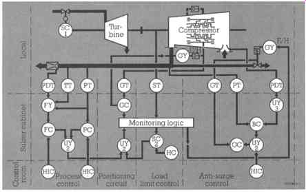
FIG. 27 Antisurge control system and combined discharge pressure/power limit
control system: SC 1-Speed controller; E/HGY-Electrohydraulic converter; PDT-
Differential pressure transmitter; TT- Temperature transmitter; PT- Pressure
transmitter; GT- Position feedback transmitter; ST- Speed transmitter; FY-
Computer; GC- Positioning controller; SC 2 - Load limit controller; UY 3 -
Function generator; FC- Volume controller; PC- Pressure controller; BC- Antisurge
controller; UY 2 - Minimum-selection relay; HC- Reference value station; HIC-
Manual station. (Sulzer Turbo Ltd., Zurich , Switzerland )
Load Limit Control
Malfunctioning in the steam or condensate system of the driving turbine may lead in certain circumstances to an undesired drop in speed. In such cases, the stator blades will be closed to such an extent by the load limit controller SC2 that the speed will remain nearly constant. The speed controller SC 2, which is equipped with the reference value station HC, receives its input signal from the speed transmitter ST and has priority over the process controller with minimal selection relay UY2, when necessary.
Antisurge Control System
System to maintain stable operation of the compressor, even when the process operating point moves into the unstable range of the compressor performance characteristic.
The pressure transmitter PT is used to determine the actual value. A differential pressure transmitter PDT and a function generator UY 3 are employed for setting the reference value. This computer enables the response line (blow-off line) to be well adapted to the surge limit. The output signal of the antisurge controller BC acts by way of the minimum selection relay UY 2 on the positioning controller GC of the blow-off valve. The valve can also be opened by the manual station HIC and override the antisurge controller. The positioning circuit for the blow-off valve comprises the positioning controller GC, the electrohydraulic converter GY and the position feedback transmitter.
Monitoring Logic
The monitoring logic supervises various controller reference values, the speed of the set, time-dependent operations such as start up and the positioning of the final control elements. The system facilitates the determination and processing of any disturbances in the final positioning elements and transmitter signals.
General System Layout
The control system of axial compressors is designed for all types of drive and the most diverse process applications. It corresponds to the latest knowledge and experience in the field of electronic control.
++Transmitter according to the 2-wire system; standard signals 4-20 mA
++Isolating amplifier in the case of external measurement data
++Plausibility supervision for the determination of measurement data faults
++Output tracking for automatic changeover to manual control made in case of measurement failure
++Impulse technique of the control units
++Positioning elements driven by hydraulic servomotors and controlled by electro-hydraulic converters
++Two changeover contacts for each output for alarm and control purposes.
Features of the System
++Proven building block system for compressor installations
++Central simulation and control unit
++Integrated monitoring system acting directly on the final positioning elements
++Monitoring of important values according to the "20-of-3 system"
++Three-week tests on load at works under elevated temperature and supply voltage
++Electronic fuse protection for each individual functional group
++Optimal adaptation of the system to the individual control parameters, thanks to the modular system
++Self-contained functional units as plug-type modules
++Easy extension and modification at any time thanks to the clearly defined wiring plans
++Simple interface in the case of the use of process computers.
Typical Compressor Plant P & I Diagrams FIG. 28(a) depicts automatic control by means of adjustable stator blades.
FIG. 28(b) depicts remote setting of the adjustable stator blades.
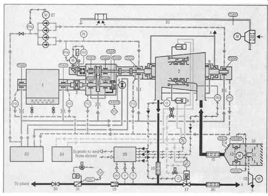
FIG. 28(a) Automatic control by means of adjustable stator blades
List of major components for automatic control of adjustable stator blades (FIG. 28(a))
1 Driving motor 2 Gear coupling, oil-filled 3 Speed-increasing gear with thrust collars, thrust bearing on the slow-running shaft 4 Main oil pump, laterally flanged to the gear-box, driven by the slow-running gear shaft 5 Solid coupling 6 Turning gear 7 Axial compressor with adjustable stator blades 8 Labyrinth glands 9 Servomotor of the stator blade adjusting mechanism 10 Two-stage air intake filter consisting of: 11 Inertia dust separator (1st stage); 12 Dust evacuation fan; 13 Roll-band filter (2nd stage) with driving motor and automatic forward feed control; 14 Bypass flap with open alarm switch GAO 15 Suction silencer 16 Non-return valve with air-operated closing cylinder and solenoid valve 17 Antisurge valve, hydraulically operated 18 Venturi tube for measuring the air flow 19 Discharge silencer 20 Blow-off silencer 21 Noise-attenuating hood 22 Ventilation fan with silencer 23 Lube oil supply unit 24 Control oil supply unit 25 Electronic control system and monitoring logic 26 Discharge isolating valve; 27 Jacking oil pump
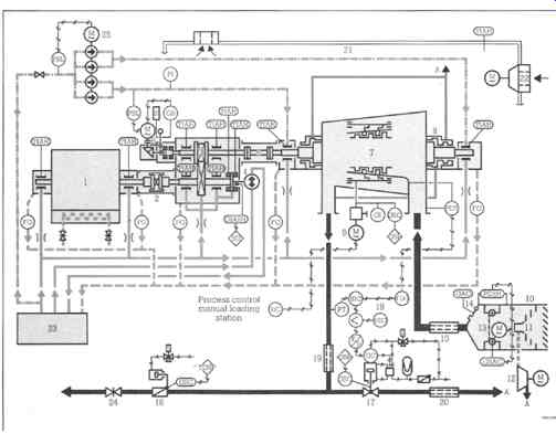
FIG. 28(b) Remote setting of the adjustable stator blades
List of major components for remote setting of adjustable stater blades (FIG. 28(b)) 1 Driving motor 2 Gear coupling, oil-filled 3 Speed-increasing gear with thrust collars, thrust bearing on slow- running shaft 4 Main oil pump, laterally flanged to the gear-box, driven by the slow-running gear shaft 5 Solid coupling 6 Turning gear 7 Axial compressor with adjustable stator blades 8 Labyrinth glands 9 Electric servomotor and gear for remote setting of stator blade 15 Suction silencer 16 Non-return valve with air-operated closing cylinder and solenoid valve 17 Antisurge valve, pneumatically operated with air failure to open safety device (pressure accumulator) and solenoid valve.
The antisurge valve is controlled via an electric/pneumatic converter E/P by the antisurge controller BIC. Manual control of the valve is possible in the sense "Valve to open" (the antisurge controller thereby being overridden) by operating the manual loader HIC adjusting mechanism by means of 18 Function generator, computing controller HIC; gear with local manual intervention facility 10 Two-stage air intake filter consisting of: 11 Inertia dust separator (1st stage)
12 Dust evacuation fan 13 Roll-band filter (2nd stage) with driving motor and automatic forward feed control 14 Bypass flap with open alarm switch GAO the set points of the antisurge controller BIC in function of the aspired air flow rate 19 Discharge silencer 20 Blow-off silencer 21 Noise-attenuating hood 22 Ventilation fan with silencer 23 Lube oil supply unit 24 Discharge isolating valve 25 Jacking oil pump
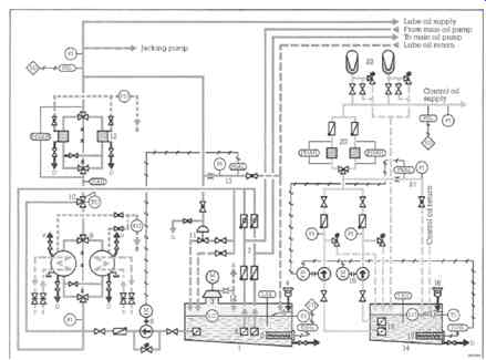
FIG. 29 Typical oil supply schematic
Scope of supply and functional description for oil supply components (FIG. 29)
1 Lube oil tank with auxiliary equipment 2 Electric oil heaters 3 Oil mist fan 4 Filling sieve and breather 5 De-gasifier plates 6 Suction strainers 7 Safety arrangement (4 non-return valves) in the main oil pump suction and discharge lines to prevent backflow of oil if the compressor and hence the main oil pump should accidentally turn in reverse direction 8 Auxiliary oil pump, electric-motor-driven; automatic start up of the pump in the event of oil pressure dropping 9 Twin oil cooler, each of the coolers being sized for full flow, with transfer valve for cooler changeover during operation 10 Oil temperature control valve, maintaining constant the oil cooler oil outlet temperature by bypassing more or less the oil around the cooler 11 Oil pressure control valve, maintaining constant the lube oil supply pressure 12 Twin oil filter, each of the filter screens being sized for full flow, with transfer valve for filter changeover during operation and pressure loss indicator as well as alarm PDIAH 13 Testing device for checking the automatic start up of the auxiliary oil pump 14 Control oil tank with auxiliary equipment 15 Electric oil heaters 16 Filling sieve and breather 17 De-gasifier plates 18 Suction strainers 19 Control oil pumps, motor-driven; one pump in operation, the other one acting as standby pump, starting automatically if control oil pressure drops 20 Control oil filters, two in parallel each one sized for full flow, with transfer valve for filter changeover during operation and pressure loss alarm PDAH 21 Testing device for checking the automatic start up of the standby pump 22 Bladder-type pressure accumulators assuring that the compressor stator blades are closed properly in the event of control oil pump failure
Symbols for the above schematic diagrams
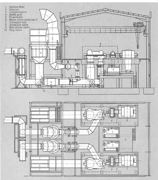
FIG. 30 Layout drawing of a compressor, type AV, with driving motor and
gear unit. (Sulzer Turbo Ltd., Zurich , Switzerland )
Typical plant layout
FIG. 30 shows an example of a blast furnace blower plant. Figures 12-31 to 12-38 are photographs in various field situations.
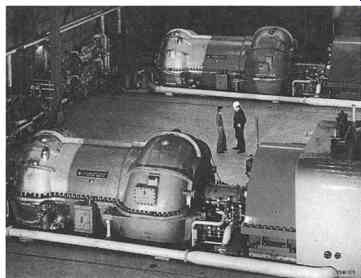
FIG. 31 Two steam-turbine-driven axial compressors delivering 330000 Nm^3/h
and 450000 Nm^3/h of air at 5.3 bar to the blast-furnace plant of Hoogovens,
ljmuiden (NL). Power input 29 000 KW and 40 700 kW respectively. (Sulzer Turbo
Ltd., Zurich , Switzerland )
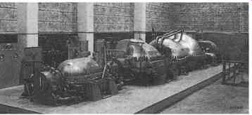
FIG. 32 One of the two motor-driven compressor/expander trains in the nitric
acid plant of Norsk Hydro at HerCya (N). From left to right: axial tail-gas
expander, 123 000 Nm^3/h, 7700 kW; centrifugal nitrous gas HP compressor,
140000 Nm^3/h, 4330 kW; axial nitrous gas LP compressor, 180000 Nm^3/h, 12
150 kW. (Sulzer Turbo Ltd., Zurich , Switzerland )
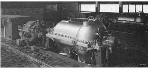
FIG. 33 Two axial water vapor compressors for a thermocompression/evaporation
plant in the Austrian salt works Steinkogel. Capacity 81 t/h or 95 000 m^3/h,
power input 3520 kW each. The compressors are equipped with a special washing
device, periodically injecting de-mineralized water in order to remove salt
deposits which may otherwise accumulate on the critical internal parts within
the flow-path. (Sulzer Turbo Ltd., Zurich , Switzerland )
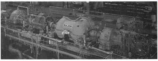
FIG. 34 Turbocompressor train for the nitric acid plant of SASOL, Secunda
(South Africa), on the test bed From left to right axial tail-gas expander
111000 Nm^3/h, 10950 kW; centrifugal nitrous gas compressor, 122 500 Nm3/h,
axial air compressor, 139000 Nm^3/h, 11890 kW condensing extraction steam
turbine 6500 kW, 6600 rev/min. (Sulzer Turbo Ltd., Zurich, Switzerland
)
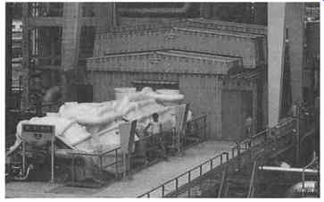
FIG. 35 one of the three identical two-casing axial compressor sets for
the compression of 290000 Nm^3/h of a hydrocarbon mixture from 1.42 to 39.2
bar, installed in the natural gas liquefaction plant (LNG) at Skikda ( Algeria). Each steam-turbine-driven compressor train requires a power input of 78
MW. (Sulzer Turbo Ltd., Zurich , Switzerland )
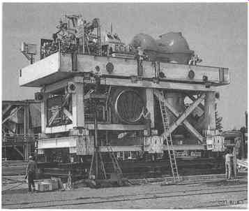
FIG. 36 Completed air compressor module incorporating axial compressor A
71-10, 13-MW steam turbine and condenser. The direct driven compressor
supplies 231 000 Nm^3/h of catalyst regenerating air at 3.4 bar for a fluid
catalytic cracking unit (FCCU) of Statoil at Mongstad , Norway. (Sulzer Turbo
Ltd., Zurich , Switzerland )
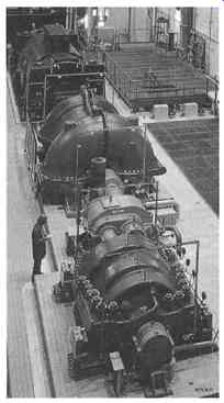
FIG. 37 The word's first compressed-air energy storage (CAES) installation,
operated by the Nordwestdeutsche Kraftwerke AG (NWK) at Huntorf ( Germany
). The compressor unit, consisting of an axial LP air compressor and a
centrifugal HP compressor coupled through a gear to the motor/generator of
the BBC gas turbine, pumps 300 000 Nm^3/h at 46 to 72 bar into a salt cavern
during the charging cycle and absorbs 60 MW. The gas turbine produces 290
MW during the peak-load period. (Sulzer Turbo Ltd., Zurich , Switzerland )
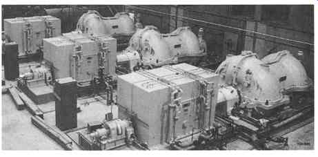
FIG. 38 Three of four identical axial compressor sets installed at the US
Air Force Aero-propulsion System Test Facility of the Arnold Engineering Development
Center , Tullahoma , Tennessee , USA . Each compressor delivers 352 000 Nma/h
of air at 3 bar and absorbs 18000 kW. Another two 35-MW compressors of the
same frame size can boost the air to 9.6 bar, but both LP and HP machines
are operated at different pressure levels for aircraft engine tests at various
simulated flight conditions. (Sulzer Turbo Ltd., Zurich , Switzerland )