As stated in the introduction to the preceding section, dynamic compressors are machines in which air or gas is compressed by the mechanical action of rotating components imparting velocity and pressure to the air or process gas. In an axial compressor, as the name implies, flow is in the axial direction, i.e., parallel to the axis of rotation. Axial compressors are basically high-flow, low-pressure machines, in contrast to the lower flow, high-pressure centrifugal compressors.
FIG. 1 shows the performance characteristics of a centrifugal and an axial compressor at constant speed for the same operating conditions. From this figure, a direct comparison of the characteristics is easy. The "turndown" capability of the centrifugal is much larger than that of the fixed geometry axial. The range of operation is greatly increased through the use of variable geometry.
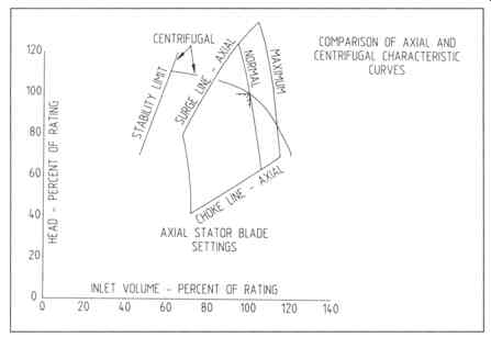
FIG. 1 Comparison of axial centrifugal characteristic curves. (Dresser-Rand Co.,
Phillipsburg , N.J. )
FIELD OF APPLICATION
Axial flow compressors have found wide use in refineries, petrochemical plants, and steel mills. Particularly in refineries, applications formerly handled by centrifugal units are now handled by axial flow compressors. This is due to several trends: first, plant sizes are growing dramatically, which brings the air requirements up into a desirable range for axial compressors; second, due to rising energy costs, there exists an increasing trend toward higher efficiencies; and third, technological improvements have made axial compressors more reliable than ever before.
Axial compressors are generally more efficient than centrifugal compressors in the common flow range, depending on conditions. An axial compressor will also generally be smaller than a centrifugal compressor designed for the same flow rate.
Although the axial flow compressor requires more stages due to the lower pressure rise per stage, the diametral size is much greater in a centrifugal compressor in order to pass the required air flow. The axial compressor must operate at significantly higher speeds for the same condition and is usually more costly than a comparable centrifugal compressor. In applications where speed is not a major consideration, an efficiency and size versus cost evaluation must be made.
Petroleum Refineries
These are probably among the largest current users of axial flow compressors for providing the air for catalytic cracking. This service requires 50,000 cfm to 300,000 cfm at discharge pressures from 25 to 50 pounds per square inch gauge (psig). FIG. 2 depicts a typical installation.
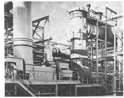
FIG. 2 The first power recovery train in fluid catalytic cracking service
in a refinery and the equipment train. The equipment train comprises tandem
motor-axial compressor-steam turbine-hot-gas expander units. The compressor
is rated at 127,900 inlet cfm with a discharge pressure of 34 psig. The train
power rating is approximately 15,000 HP. (Dresser-Rand Co., Phillipsburg ,
N.J. )
Butadiene Plants
Air capacities from 60,000 to 150,000 inlet cfm and discharge pressures from 20 to 30 psig with atmospheric intake enable the axial compressors to perform well in this application.
Nitric Acid Plants
In plants with capacities in excess of 500 tons per day, axial-centrifugal compressor combinations are frequently used to handle flows from 20,000 to greater than 80,000 cfm (approximately 100 cfm per ton-day) and discharge pressures from 110 to 130 psig for the combined compressor string. Power recovery expanders utilizing process "tail gas" usually drive the compressor string.
Air Separation Plants
Axial compressors are used almost exclusively for higher flow air services. Services range to 100,000 cfm and discharge pressure up to 100 psig.
Blast Furnaces
Axial compressors are replacing many of the older, less efficient centrifugal blowers.
The compressors provide air at discharge pressures from 30 to 90 psig and flows from 125,000 to 350,000 cfm.
In addition to the common processes described above, axial compressors are also often used for wind tunnel service, waste treatment facilities, specialized testing facilities, and are being developed for co-generation combustion service.
BASIC AXIAL COMPRESSOR PERFORMANCE CAPABILITIES
As described earlier, the axial flow compressor is a machine with wide ranges of capacity, i.e., flow, pressure, and horsepower required.
Axial compressor flow capabilities on the low end of the range, say 20,000 to 75,000 cfm, obviously overlap the higher range of centrifugal compressor coverage.
It is within this low flow region where cost and size evaluation, along with driver considerations, must control the selection. Above this range, however, axial compressors are often the obvious choice. The physical size of the axial compressor is far smaller than the comparable centrifugal machine that would be required.
In many high-flow situations, the axial is a better match for the drivers that will probably be selected.
To increase the pressure capability of the axial flow compressors, multiple casing designs have also been developed. These are known as biaxials and triaxials.
As their names imply, these are two- or three-body axial compressor trains capable of pressure ratios up to approximately 12 to 1. The machines were developed for use in nitrogen injection services.
Horsepower requirements for axial flow compressors range from 3000 HP to 65,000 HP for single casing units. Horsepower inputs vary with the flow and pressure requirements of the service. A simple formula for the approximate power requirement of an axial flow compressor would be:
where ...
WW = Wet weight flow, lb/min
R = Gas constant, ft- lbf/lbm- ~
T -- Inlet temperature, degree
PR = Pressure ratio
FUNDAMENTALS OF AXIAL COMPRESSOR DESIGN
A multistage axial flow compressor has two or more rows of rotating components operating in series on a single rotor in a single casing. The casing includes the stationary vanes (the stators) for directing the air or gas to each succeeding row of rotating vanes. These stationary vanes, or stators, can be fixed- or variable-angle, or a combination of both.
A typical axial flow compressor cross section is shown in FIG. 3; FIG. 4 shows an axial compressor with the top half removed. The major components and their nomenclature are depicted in FIG. 3 for reference use throughout this section.
There are two basic types of blading that are employed in an axial flow compressor; these are obviously rotating and stationary. A brief overview of these parts is presented next.
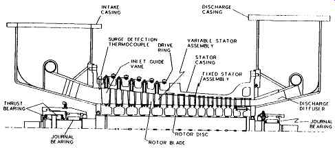
FIG. 3 Typical axial flow compressor cross section. (Dresser-Rand Co., Phillipsburg, N.J.)
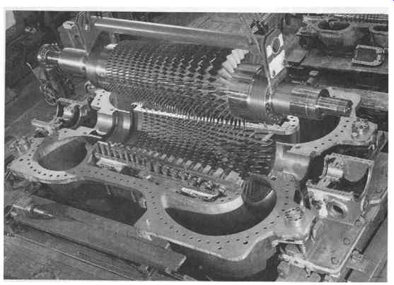
FIG. 4 Axial compressor, type AV 100-16, during erection Two identical steam-turbine-driven
machines are supplying air to the blast furnace of a British steel works.
Suction volume 560 000 Nm^3/h discharge pressure 6.2 bar power input 52 000
kW each. (Sulzer Turbo Ltd., Zurich , Switzerland .)
Stationary Blades
Inlet Guide Vanes
The first row of stationary blades is unique. These blades are referred to as inlet guide vanes. These vanes are designed to provide pre-rotation to the air or gas stream prior to entry into the rotor blades. Blade profiles have airfoil-shaped cross sections.
Stator Vanes
The majority of the stationary blades within the compressor are simply called stators.
There exist two types of stator vanes, variable and fixed.
Variable Stator Vanes. Variable stator vanes fit through the stator casing or a blade carrier of some kind (depending on the manufacturer's design) and are attached to a drive mechanism that moves the vanes with respect to the air flow. A more detailed description of the actuating system is provided below. The inner end of each vane can be shrouded to improve the stress condition and to reduce the interstage losses through sealing strips mounted in the inner shroud.
The actuation system used to move the variable stator section is usually a combination of linkages designed to move the vanes simultaneously. One type of linkage system is shown in FIG. 5. Each variable stator vane is connected to a driving ring by a small link. These rings, one for each stage of blades, are individually connected to a main driving shaft so that the stages move simultaneously. The drive shaft is connected to a hydraulic (or pneumatic) power piston, which, through push-pull effect, opens and closes the stator vane.
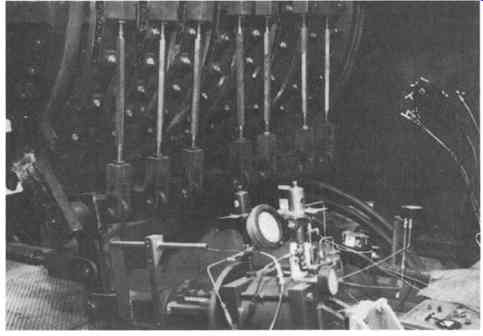
FIG. 5 A typical variable stator vane actuation system and linkage arrangement.
(Dresser-Rand Co., Phillipsburg , N.J.)
Different designs are chosen for this system by the various manufacturers.
Desirable features would include the following:
1. Solid or "tight" linkage systems to prevent slow or inefficient actuation of the vane position.
2. A minimum number of "joints" in the system that can wear with time and become loose or seize due to the presence of dirt.
3. Dual power cylinders (one on each side of the unit) to provide even movement of all vanes.
Fixed Stator Assembly. The fixed stators are typically welded assemblies comprising the vanes and inner and outer shrouds. These assemblies are fitted into machined grooves in the stator casing. The fixed stator assembly is also fitted with sealing strips for leakage reduction.
Rotating Blades
The rotating blades within the axial compressor are appropriately called rotor blades.
These are National Aeronautics and Space Administration (NASA)-developed tapered and contoured airfoil sections. The rotor blades have an attachment on one end to allow for assembly within the rotor.
A simplified partial section of an axial flow compressor flow path is shown schematically in FIG. 6. The basic components would typically include the following:
++An inlet duct to collect and accelerate the gas toward the inlet guide vanes with minimum pressure losses.
++A row of inlet guide vanes to impart pre-whirl to the gas stream in the direction of rotation for smooth entry to the rotor blades and for the control of the inlet relative Mach number.
++A multiplicity of stages, each consisting of a row of rotor blades and a row of stator vanes of airfoil shape, to increase the static and/or total pressure of the flow.
The total energy transfer to the gas stream is accomplished by the rotor blades.
The hub stagger (the angle between the blade chord and the axis of rotation) is fixed, thereby fixing the amount of work done by each stage and consequently fixing the number of stages necessary to achieve the required discharge pressure.
The standard frame design is adjusted to meet the required air flow by varying the rotor and stator blade heights and the unit operating speed.
++A row of exit guide vanes, oriented to remove the whirl component from the flow leaving the last stage stator vanes, and to begin deceleration of the flow.
++A discharge diffuser to further decelerate the flow and to convert the residual velocity energy into static pressure rise.
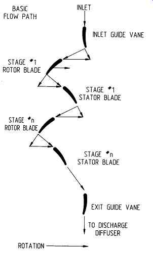
FIG. 6 Schematic presentation of an axial flow compressor flow path. (Dresser-Rand
Co., Phillipsburg , N.J. )
Natural Frequencies and Resulting Stresses
Due to the inner and outer shrouding of the fixed stators and the internal shrouding and casing support of the variable stators, vibration occurring at component natural frequencies and the resulting stresses in these components are not of major concern.
If a specific manufacturer does not use shrouds on both inner and outer surfaces, it is important to review the frequency analysis of the stationary vanes in the same manner as discussed below for the rotor blades.
Since the rotor blades are mounted in a cantilever beam arrangement, i.e., one end unsupported, natural frequency excitation and the resulting stresses must be thoroughly analyzed by the designer. Clear definition of the natural frequencies of the blading, possible sources of excitation within the unit, and the resulting stress levels should be provided by the manufacturer. This should be presented in the form of Campbell and Goodman Diagrams for the compressor blading. (Refer to Section 5 for a discussion of these diagrams.) Evidence of the accuracy of the information, in the form of test data or successful long-term operating experience, should be made available by the manufacturer and should be reviewed by the purchaser. Similar scrutiny is appropriate for thrust beating designs.
OPERATIONAL LIMITATIONS
The successful prediction of the performance of an axial compressor requires knowledge of the flow behavior likely to be encountered in the machine. In certain areas of the operating characteristic, accurate prediction of the performance is not possible. Violent overall instabilities identified as stall, surge, and choke complicate these predictions.
Stall
Stall is a commonly used term with regard to axial flow turbomachinery. It is too often incorrectly used as a cause of problems, mainly due to a misunderstanding of the true flow behavior during a stalled condition. Stall occurs when the flow separates from the surface of the blade. An aerodynamic disturbance is formed downstream of the point of separation.
Stall is a generalized term. It is often used with additional descriptors to explain the flow condition that causes the separation. For instance, the separation can occur on either side of the airfoil. High positive incidence stall, caused when the angle between the flow and the inlet to the rotor blade is too large, causes separation of the airflow from the suction, or convex, side of the airfoil. High negative incidence stall causes separation of the airflow from the pressure, or concave, side of the airfoil.
Conditions of rotating stall can be established when a group of blades becomes stalled. This is a phenomenon of stall cells being created within a stage. As the first blade stalls, it causes a disturbance to the airflow of the adjacent blade, eventually causing it to become stalled. As each subsequent blade becomes stalled, the last blade in the patch of stalled blades begins to recover. Thus, the effect is a rotating patch of stalled blades.
Whether a few blades experience stall or a rotating stall cell is formed, the mechanical damage possibly caused by this unstable aerodynamic condition can be significant. It is difficult to determine the actual loads induced on the blades during such an event. Laboratory testing has shown that loading levels can reach ten times normal levels.
Surge
As with any dynamic compressor, surge occurs when the slope of the pressure ratio versus capacity curve becomes zero. It is associated with the complete breakdown of flow through the machine, and it takes place when several adjacent stages are subjected to high positive incidence stall. At any given speed, as the inlet flow is reduced, a point of maximum discharge pressure is reached. As flow is further reduced, the pressure developed by the compressor tends to be lower than the pressure in the discharge line and a complete flow reversal of an oscillatory nature results. The reversal of flow tends to lower the pressure in the discharge line and normal compression resumes. If no change to either the system back pressure or the operation of the compressor occurs, the entire cycle is repeated. This cycling action is an unstable condition varying in intensity from an audible rattle to violent shock, depending on the energy level of the machine. Intense surges are capable of causing serious damage to the compressor blading and seals. The uncertainties surrounding this oscillating flow are cause for concern.
Surge Control
It is standard procedure at process plants to install reliable antisurge control equipment in the compressor piping to prevent operation in the surge region. A typical surge control system should incorporate or encompass recycle loops, i.e., valved bypass piping to provide sufficient flow through the compressor to keep it away from surge. Experience points to the following requirements:
++The system is to be electronic rather than pneumatic for the fastest response time, and the surge valve must be interlocked with the trip circuit such that it immediately opens on a train trip.
++The control system logic requires flow, pressure, and stator vane position input.
++The surge valve positioner-operator system must be capable of driving the valve fully closed to fully open in one second and fully open to fully closed in ten seconds.
++The surge valve should open on the loss of any input signal or operator medium.
++The surge valve should be sized to pass full flow at any point along the surge line with the valve at 60% open and with full consideration given to the downstream system pressure drop. The point on the surge line requiring the largest valve and discharge system is normally at maximum speed with stators full open, but a point at lower flow with a lower discharge pressure may in some instances dictate size.
++A check valve should be installed close to the compressor discharge just down- stream of the surge valve connection in the discharge line.
In addition to the antisurge control system discussed above, a thermocouple detection system can also be employed to determine the presence of the surge recycling effect.
When an axial flow compressor experiences surge, it essentially undergoes a momentary internal gas flow reversal. This flow reversal will slightly elevate the stator casing inlet gas temperature. The increase results from the intermediate gas, which has been heated by compression, flowing back into the inlet area.
This detection system should be implemented in addition to a primary antisurge control system. It consists of thermocouples installed in the airstream just upstream of the inlet guide vanes. Upon reaching a predetermined setpoint, which indicates surge, a signal is sent commanding the surge control valves to go to the full open position. Upon reaching an acceptable level of temperature, i.e., the compressor has recovered from the surge, the surge valves are permitted to return to the normal position and control of the surge valve is returned to the primary surge control system.
Choked Flow
Choking occurs when the slope of the pressure ratio versus capacity curve approaches infinity. It occurs at the point where a further increase in mass flow through the cascade is not possible. Choked flow is associated with the flow velocity reaching a Mach number of 1.0 at some cross section within the machine.
Unlike with surge, there is no accompanying increase in noise level or machine vibration amplitude. Choke is a "quiet" phenomenon, which, when operation continues for extended periods of time, can cause damage to the rotating blades, with eventual failure possible.
Choke Control
A choke control system is needed to avoid operation within the detrimental region.
A typical system would encompass a choke valve designed for minimum pressure drop in the open position and capable of full response in ten seconds. The valve would open in the event of signal failure and would respond to a control system using differential pressure (flow) and discharge pressure as inputs.
Surge and choke conditions are affected by geometry, speed, and ambient conditions. Each of the aerodynamic instabilities is most likely to occur within a particular primary region of the performance characteristic. FIG. 7 shows these various regions.
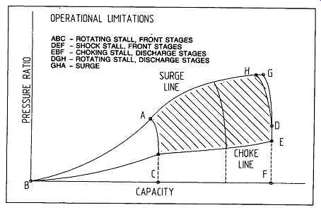
FIG. 7 Operating envelope for axial compressors. (Dresser-Rand Co., Phillipsburg
, N.J. )
STANDARD MAINTENANCE CONSIDERATIONS
Like all machinery, axial flow compressors require both periodic preventive and corrective maintenance. A daily review of key operating data is quite often the best preventive maintenance strategy for axial flow compressors. These data should include various ambient and process parameters that define the operation of the unit.
In addition, machinery vibration and bearing temperature data should be logged.
While these daily (or weekly) records may fail to tell the entire operating history, they can nevertheless establish trends of operation, i.e., has the present problem been progressing slowly for several days or weeks, or is it a sudden change? Quite often, these records can provide the information essential to avoiding unscheduled shutdowns simply through the establishment of normal trends. Just as important, an abrupt reading might be cause for immediate investigation. Such a situation may call for an unscheduled shutdown to reduce risking catastrophic failure.
To maximize the benefits available from these records, it will be necessary to be consistent. Records must be maintained daily, since without the proper parameters being accurately recorded, the validity of the record could rightly be questioned.
A typical listing of the parameters that should be included in the daily log is outlined in Table 1. It is recommended that the operators discuss the list with the equipment manufacturer and add any items that both parties feel are critical to the analysis of operational fitness of the machinery. Data logging could be done manually or automatically, using either a process computer or a dedicated machinery condition computer.
Typical items to visually inspect on a regular (daily) basis are listed below.
++Check the unit for oil leaks at flanges, instrumentation outlets, vane actuator connections, etc.
++Observe the operation of the stator vane linkage during a change of its position.
Check for binding of any components. Ensure smooth movement. "Jumping" or sporadic movement usually indicates mechanical binding or foreign matter in linkage joints.
++Listen to the unit for unusual sounds, such as rubbing (seals or blades) or leaking gaskets. If the sound intensity is significant, investigate the probable causes.
++Check bearing oil drain sight flow indicators to ensure good oil flow through the beatings. Note any significant change in the running level, e.g., much fuller than normal, less flow than normal.
====
TABLE 1 Parameters for Condition Monitoring of Axial Compressors
Inlet temperature Inlet pressure Inlet relative humidity (dew point temperature)
Unit flow (at inlet or delivered)
Discharge pressure Discharge temperature Stator vane position Unit speed Radial vibration amplitude Axial position Surge valve position Choke valve position Radial bearing pad temperature Thurst bearing pad temperature Lube oil supply temperature Lube oil supply pressure Lube oil drain temperatures Lube oil total flow
====
Compressor Internal Cleaning
Modem axial flow compressors will operate for long periods between shutdowns.
Well though-out metallurgy is essential in the design and manufacture of rotor blade components. External surface coatings are applied to protect the blades from corrosive and erosive attack. Along with the addition of coatings, compressor blade life may be increased by installing inlet air filtration systems.
On-line cleaning of internals is usually considered after severe degradation of compressor performance is noted. With a properly sized and operating inlet filtration system, fouling should be minimized. However, on-line cleaning is treating a symptom rather than curing the cause. The problem is more directly addressed through investigation of the air quality entering the compressor. Proper design of the inlet filtration system has always been important to the manufacturer: proper maintenance of the system must become similarly important to the operator.
There are several on-line cleaning methods employed by operators depending on the process and the available cleaning methods. The question of whether or not axial flow compressors should be cleaned during on-line operation is a complex one.
Due to possible problems with each of the cleaning methods currently used, it is appropriate to consult the manufacturer. Below is a short description of some of the systems currently in use. The possible problems, from both the process operation and machine reliability points of view, are also highlighted.
The most effective cleaning procedure for the compressor is a low-speed water/kerosene wash. It is to be performed at approximately 30% of normal speed.
The compressor is essentially soaked in the cleaning solution for approximately thirty minutes. A rinsing cycle removes residual cleaning fluid, and returning to full speed effectively dries the internal components of the compressor.
This is technically the safest and most effective cleaning method. It is, however, the least desirable from the operational view, since it requires the unit to be removed from the process for approximately one hour. This is the approximate time required to complete the procedure.
A second process employed today is a water/solvent spray wash system. It is to be used at full speed and, in most cases, is not detrimental to the process. This system requires the addition of a spray nozzle assembly into the inlet casing of the compressor unit. Commercially available cleaning fluids are used.
Possible problems include the incomplete atomizing of the fluid prior to entry into the compressor. The blading could be damaged by the impingement of large water particles. In addition, pulsations created on the rotor blades from the spray nozzles add another excitation to be considered in the natural frequency and stress analysis. Most importantly, while this system is somewhat effective on the first stage on the machine, the cleaning efficiency is drastically diminished at each successive stage. The cleaning medium is simply centrifuged to the casing wall and has little effect on either the rotating or stationary blades downstream.
The third method of on-line cleaning is one that has been employed in similar equipment for some time. This procedure entails the introduction of crushed walnut shells (or apricot pits) into the airstream. These "cleaning media" are introduced into the piping upstream of the inlet casing. They are fed at a rate of approximately 50 pounds every two minutes.
The possible problems with such a system are very similar to those encountered with the spray wash system. The solids are centrifuged to the casing wall so quickly that the effectiveness of the system is severely diminished beyond the first stage. In units employing blade coatings, nut shells or pits can cause accelerated erosion of the blade coatings. In any event, strict control of the injection rate will be required.
Corrective Maintenance
Corrective maintenance may become necessary every three to five years. At that time, inspection and replacement of wearing parts is often appropriate. Prior to the inspection shutdown, an inventory of the available spare parts should be performed.
Discussions with the manufacturer should take place to determine that proper quantities of spares are available to ensure a complete and timely turnaround of the machine.
A typical inspection and replacement shutdown may require approximately two weeks. During that time, typical inspections would include the following:
++Rotor blade cleaning and magnetic particle nondestructive testing to ensure the integrity of parts if a complete spare rotor is not available.
++Nondestructive testing of rotor discs, particularly in the area of blade attachment, to check for evidence of stress-related damage. The normal method is dry powder magnetic particle inspection.
++Liquid penetrant nondestructive testing of stationary blading to ensure the integrity of the welded joints within the assemblies.
++Beating clearance check on the previously installed beatings as well as the new bearings. Visual and dimensional inspection of the beatings for evidence of rubbing, wiping, and unusual wear.
++Rotor check balance to correct any unbalance introduced by rotor blade replacement. Rotor tip clearance check to ensure that proper running clearances are established for safe operation.
++Variable stator vane linkage check to replace any worn bushings or locking/locating pins.
++Instrumentation check to ensure the operational indicators to be recorded are accurate and available.
++Coupling inspection for tooth wear on gear couplings and diaphragm check on diaphragm couplings.
++Axial rotor-to-stator clearance check during reinstallation of the rotor assembly to ensure the proper rotor-to-thrust bearing positioning.
++Seal clearance check on all shaft and bearing assemblies. The shaft should be inspected on removal from the unit for any signs of seal contact.
++Inlet filtration system check to ensure the filter elements are clean and secure. In addition, the inlet piping should be inspected from the inside to ensure no loose pieces exist or foreign objects are inside, which could enter the unit and cause damage to the compressor.
SELECTING AN AXIAL COMPRESSOR
(For additional reference material, see also appendices on barrel and isotherm compressors in the previous section, as well as environmental factors involved in Environmental Engineering and Management: Sustainable Development for the Power Generation, Oil & Gas and Process Industries, Butterworth-Heinemann 1998). Axial compressors are being used increasingly for applications which not long ago were clearly considered the domain of centrifugal machines. Thanks to their high specific flow capacity, the corresponding low weight, reduced space requirement and particularly their high efficiency, the axial compressors play a major role in the reliable and economic operation of modem, large-scale industrial plants.
They now form a vital and indispensable integral part of installations like blast furnaces, air separation plants, fluid catalytic cracking units, nitric acid plants, jet-engine test facilities, thermocompression, liquefied natural gas (LNG) and synfuel processes.
The present-day technique of modem axial compressors is based on decades of experience. Thousands of units are in continuous operation in industrial plants all over the world, to which thousands more serving as combustion air compressors of gas turbines have to be added. The power input ratings of the industrial applications vary between 2000 and 90000 kW. With a view to economical manufacturing and stocking of the major components, the range of compressors has been standardized. The stocking of major components facilitates prompt delivery of machine parts such as rotor blades and stator blades, bearings, joints, etc., for service requirements. The systematic design of components over the whole range of sizes enables the compressor to be adapted optimally to the required operating conditions. Measurements conducted on the blading of various designs and sizes ensure exact conformity of the design data with the operating conditions.
Product Range
The axial compressors manufactured by one of the major producers, Sulzer, come in two types:
Type A Compressors with fixed stator blades (FIXAX)
Type AV Compressors with adjustable stator blades on all or only some stages at the inlet (VARAX)
Each type consists of 12 geometrically graduated sizes with rotor diameters extending from 40 to 140 cm. This completely covers a suction volume range of 70,000 to 1250000 m^3/h.
The required compressor size and number of stages, together with the corresponding standardized overall length, are selected according to the suction volume and the thermodynamic head.
Type A (FIXAX)
The A-type FIXAX compressor is generally used whenever the driver is a steam turbine, a split-shaft gas turbine or a variable-frequency high-speed synchronous motor. The required operating points can be attained by speed variation, and there is basically no need for adjustable stator blades. Fixed-blade machines are also selected for installations where only minor flow variations are required, or if the mass flow is adapted by variation of the suction pressure as in aerodynamic test facilities, for example.
Type A V (VARAX)
The AV-series with adjustable stator blades permits a large stable operating range at constant speed. It is therefore used for constant-speed electric motor drive.
Nevertheless, this type is being increasingly preferred for steam turbines and single- shaft gas turbines as well. In this particular case, the stator blade control either facilitates operation with limited speed control range (increased reliability of operation for certain turbine types) or, in combination with the speed control, provides an additional extension of the operating range and an improvement of the overall efficiency at part load. Furthermore, it offers the advantage of quick adaptation of the compressor to changed operating conditions without acceleration of the set -- a characteristic which is of great interest for the periodic charging of air heaters in blast-furnace blowing plants. Roughly 50% of the major axial compressors sold since 1960 have been equipped with adjustable stator blades.
Stator Blade Setting with Electric Servomotor
For a great number of processes, the reference value of pressure or mass flow is selected at the process control panel and transmitted to the compressor servomotor.
In this case this servomotor is of the electric type with the additional possibility of manual adjustment of the stator blades.
Stator Blade Control with Hydraulic Servomotor
If the process calls for automatic pressure or mass flow control, the stator blade adjusting mechanism will be operated by a synchronized pair of hydraulic servo-motors.
With the exception of the stator blades and their adjusting mechanism, the same standardized construction elements are used for both FIXAX and.VARAX types.
Performance Data -- The following diagrams (Figures 8 to 11) facilitate the selection of
Compressor size:
- Nominal diameter
- Number of stages
Using:
- Capacity
- Suction pressure
- Suction temperature
- Relative humidity of the air or gas
- Discharge pressure
- Molecular mass
- Isentropic exponent
- Compressibility factor
- The following factors and symbols are also used for the calculation:
- Power input
- Speed
- Discharge temperature
- Suction volume (actual)
- Absolute humidity
- Polytropic efficiency
Indices:
- Suction branch
- Discharge branch
- Dry
- Wet
Information: Information concerning the selection and performance calculation of an axial compressor is provided later in this section.
Important -- Experienced engineering personnel are always needed to deal with customer inquiries and optimization of equipment layout.
---
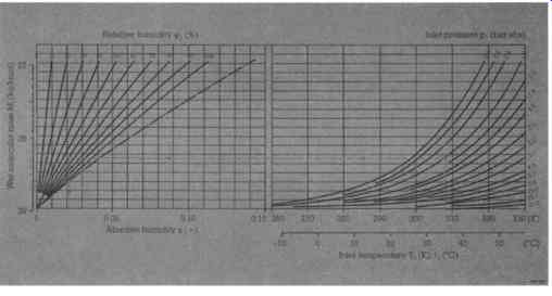
FIG. 8 Determination of the absolute humidity x and the molecular mass Mf
of the wet gas. (Sulzer Turbo Ltd., Switzerland )
Type designation
Figures 10 and 11 are valid for air at suction conditions l bar, 20~ 70% relative humidity. (Sulzer Turbo Ltd., Switzerland ) Figures 12 and 13 describe operating characteristics for type A and type AV compressors respectively. FIG. 14 is a longitudinal cross-sectional view of an AV compressor.
Depending on the specific process requirements, such as extremely high turndown, maximum efficiency within a certain range, flat or steep p-V curve, etc., various parameters of the blading may be changed in order to adapt the characteristics to such special conditions.
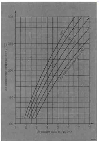
FIG. 9 Determination of the discharge temperature t2. (Sulzer Turbo Ltd.,
Switzerland )
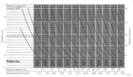
FIG. 10 Type A (FIXAX). Selection of the compressor size: nominal diameter
D (cm) = frame size as a function of the actual wet suction volume flow V
f, (m^3/s). Determination of the approximate number of stages z, nominal speed
n (rev/min) and power input P (MW). (Sulzer Turbo Ltd., Switzerland )
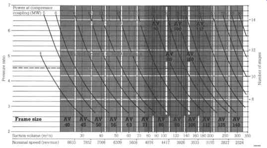
FIG. 11 Type AV (VARAX). Selection of the compressor size: nominal diameter
D (cm) =frame size as a function of the actual wet suction volume flow Vf,
(m^3/s). Determination of the approximate number of stages z, nominal speed
n (rev/min) and power input P (MW). (Sulzer Turbo Ltd., Switzerland )
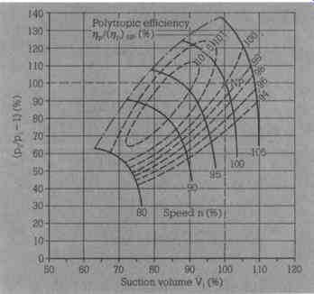
FIG. 12 Operating characteristics for a compressor, type A, with fixed stator
blades and variable speed: NP-Reference point (100%)- Design point; P2/P1-
Pressure ratio.
Valid for: constant gas data, constant inlet temperature. (Sulzer Turbo Ltd., Switzerland )
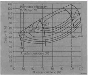
FIG. 13 Operating characteristics for a compressor, type AV, with adjustable
stator blades and constant speed: NP- Reference point (100%)- Design point;
P2/P1 - Pressure ratio; a- Angular setting of the stator blades. Valid for:
constant gas data, constant inlet temperature. (Sulzer Turbo Ltd., Zurich
, Switzerland )