AMAZON multi-meters discounts AMAZON oscilloscope discounts
(cont. from part 1)
5. Models for Water and Salt Transport through Membranes
5.1 Overview
As indicated previously, during the process of reverse osmosis water separation, two key processes occur at the same time-transport of water (solvent) and transport of salt (solute) from the high-salinity side of the membrane to the low-salinity side. At present, there are a number of models that describe the mechanism and rate of trans port of water and salts through membrane. Detailed overviews of such models and their key features are presented elsewhere. The three types of transport models that have found widest acceptance are the nonporous (homogeneous) solution-diffusion transport model, pore model, and irreversible thermodynamics model.
The most commonly used type of model for water transfer through a membrane at present is the nonporous solution-diffusion transport model. This model has found wider application than the others because of its simplicity and relatively easy confirmation by empirical tests. This model assumes that the membranes are nonporous and that water passes through them as a result of the applied net driving pressure. On the other hand, solutes (i.e., salts) pass through the membrane driven by the concentration gradient (difference) formed between the source water and freshwater sides of the membranes.
The pore model is more complex; assumes either that membranes are built of one dimensional long and narrow pores or that membranes have pores which are generated as imperfections during the production process, and as a result, some solute leaks through the membrane into the permeate side. This more complex model was created to explain why the actual water quality is somewhat lower than that projected by the nonporous solution-diffusion model.
The irreversible thermodynamics model describes the membrane performance via a dissipation function that reflects the division of the flow field into small systems that are in local thermodynamic equilibrium. The model is based on the use of differential equations to describe the flow field of these systems and to calculate the transport of multiple solutes through the membranes. Due to its complexity, this type of model have found limited application for desalination plant planning and engineering.
5.2 Nonporous Solution-Diffusion Transport Model
The nonporous solution-diffusion transport model assumes that RO membranes do not have actual pores and that water travels from the high-salinity side of a membrane to the low-salinity side by convection and diffusion in randomly shaped curvilinear intermolecular channels formed by the membrane polymer chains. The transport of water through the membranes is a three-step process: (1) adsorption of water molecules on the membrane surface, (2) convection and diffusion through the membrane, and (3) desorption from the permeate side of the membrane surface into the bulk permeate water. The rates of convection and diffusion are controlled by the net driving pressure and are also a function of the membrane permeability.
The process of salt transport is driven by the concentrate gradient between the two sides of the membrane and by the membrane's ability for solute retention through size exclusion and charge (dielectric) exclusion. Uncharged molecules (solutes or salts) are rejected due to the membrane's ability to act as a sieve for molecules larger than the molecular weight cutoff of the membranes. The molecular weight cutoff is representative of the average size of molecules that can be retained by a given membrane. For example, SWRO membranes have a molecular weight cutoff of 120 to 200 Daltons (Da). This means that most of the molecules of compounds contained in the source water that do not have charge or have only a very weak charge and are larger than 200 Da (such as most algal toxins) will be rejected by SWRO membranes.
Charged compounds (solutes) such as the ions of strong acids and bases are rejected by charged exclusion-repulsion of the salt ions by the fixed electric charges attached to the membrane surface. This observation leads to the conclusion that the larger the molecules and the higher the electric charge they have, the more likely they are to be rejected by the membranes.
Water and Salt Transport Rates
The reverse osmosis membrane separation process is closely related to two key features of the membranes: their abilities to transport water and salts. Desalination is possible because the rate of water transport of RO membranes is significantly higher than the rate of salt transport. In accordance with the solution-diffusion model, the transports of water and salts through the membrane are actually two independent processes driven by different forces.
Water Transport Rate
The water (permeate) transport rate Qp of an RO membrane is proportional to its water transport (water permeability) coefficient A-which is a unique constant for each membrane material-as well as the total membrane area S, and the net driving pressure (NDP):
As indicated in Eq.7, the ratio between the water transport rate and the surface area through which water is conveyed is referred to as the membrane permeate flux J. Therefore, membrane permeate flux (also often referred to as the membrane flux) can be represented as follows:
J = A × NDP (eqn. 10)
This formula indicates that membrane flux is controlled by two parameters-water permeability coefficient A, which is unique for each type of commercial membrane, and net driving pressure (NDP), which can be controlled by adjusting feed and permeate pressures.
Salt Transport Rate
The salt transport rate Qs is proportional to the salt transfer coefficient B-which, as the water transfer coefficient, is unique for each membrane type-the surface area S of the membrane, and the salt concentration gradient ΔC, which collectively for all salts is measured as the difference between the TDS levels of the concentrate and the permeate:
…is the concentration of the solute (salt) at the boundary layer/bulk feed flow and Cp is the concentration of solute (salt) in the permeate. The boundary layer is a layer of laminar feed water flow and elevated salinity that forms near the surface of the membranes as a result of the tangential source water feed flow in the spacers and of permeate flow in a perpendicular direction through the membranes on the two sides of the spacer ( FIG. 18).
In FIG. 18, Cb is the concentration of the solute (i.e., salt) in the feed water, Cs is the concentration at the inner membrane surface (which typically is higher than that in the feed flow), and Cp is the concentration of the solvent (i.e., freshwater salinity) on the low-salinity (permeate) side of the membrane.
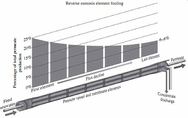
FIG. 18 Boundary layers in a membrane feed spacer.
6. Membrane Performance Factors and Considerations
6.1 Concentration Polarization
A very important factor that may have a significant impact on membrane performance is concentration polarization, i.e., an increase in salinity in the boundary layer to levels, which are significantly higher than the salinity in the feed water. This phenomenon entails the formation of a boundary layer along the membrane feed surface due to the laminar flow in the membrane feed spacers and concentration of solute (salt) in this layer. Two different types of flow occur in the boundary layer-a convective flow of freshwater from the bulk of the feed water though the membranes and a diffusion flow of rejected solutes (salts) from the membrane surface back into the feed flow (see FIG. 18). Since the rate of convective flow of water is typically higher than that of the diffusion flow of salts, the salts rejected by the membrane tend to accumulate in the boundary layer, with the highest salt concentration (shown as Cs in FIG. 18) occurring at the inner surface of the membrane. Besides salts, boundary layer also accumulates particulate solids, for the same reasons.
This phenomenon of concentration of salts and solids in the boundary layer has four significant negative impacts on membrane performance: it (1) increases osmotic pressure at the membrane surface, (2) increases salt passage through the membranes, (3) creates hydraulic resistance of water flow through the membrane, and (4) creates the potential for accelerated scale formation and particulate fouling on the membrane surface because of the concentration of salt and solids in the boundary layer. The ratio between the solute (salt) content at the surface of the membrane Cs and in the bulk feed water Cb is referred to as the concentration polarization factor ß:
ß = Cs/Cb (eqn.13)
The higher the value of ß, the higher the concentration difference and the worse the impacts of that difference on membrane performance. Taking into consideration the impact of concentration polarization, Eqn. 10 for membrane flux could be rewritten as follows:
J = A × [Fp - (ß × Op + Pp + 0.5Pd )] (eqn.14)
Similarly, Eqn. 11 for salt transport rate could be modified as follows:
Qs= B × S × (ß × Cb- Cp ) (eqn.15)
Because NDP is reduced for the same feed pressure when osmotic pressure is elevated (see Eqn. 6) and the elevated salinity in the boundary layer increases the osmotic pressure at the membrane surface, the actual permeate flow produced by the RO sys tem is reduced. In other words, an increase in the concentration polarization factor ß results in an increase of the osmotic pressure, which in turn causes a reduction in flux (i.e., lower production of freshwater).
Salt passage through the membranes is increased (i.e., salt rejection is decreased) because, as per Eqs. 11 and 12, the salt transport through the membrane is proportional to the difference in salinity from one side of the membrane to the other. Since the salinity at the feed side of the membrane is higher than the salinity in the feed solution, the salt transport is proportionally higher as well. This means that as ß increases, salt rejection is reduced and the salinity of the produced freshwater is increased.
Due to the salinity gradient and accumulation of particulate solids within the boundary layer, the hydraulic resistance of that layer is higher than that of the feed water. As a result, the available NDP is decreased and the membrane flux is reduced.
The hydraulic resistance compounds with the elevated osmotic pressure to reduce flux.
If the salt concentration in the boundary layer exceeds the solubility of sparingly soluble salts (such as calcium carbonate and sulfate) contained in the source water, these salts will begin precipitating on the membrane surface and form mineral scale. As indicated in Section 2, membrane scaling will result in reduced permeability and flux.
The magnitude of the concentration polarization factor ß is driven by three key factors: (1) permeate flux, (2) feed flow, and (3) the configuration and dimensions of the feed channels and feed spacer. An increase in permeate flux (i.e., freshwater production) increases exponentially the quantity of salt ions and particulate solids conveyed to the boundary layer and therefore exacerbates concentration polarization and particulate fouling of the membrane. An increase in feed flow, however, intensifies turbulence in the boundary layer and, as a result, decreases the thickness and concentration of the layer. Depending on configuration and geometry, the RO membrane feed/concentrate spacer and feed concentrate channel may cause more or less turbulence in the concentrated boundary layer and therefore, may reduce or increase concentration polarization.
Since feed spacer configuration and channel size are constant for a given standard RO membrane element, permeate flux and feed flow are the two key factors that deter mine the magnitude of concentration polarization. As indicated previously, the ratio between the permeate flow and the feed flow of a given RO membrane element is the permeate recovery rate of the element. Similarly, the ratio between permeate flow and the feed flow of an entire RO system is termed the RO system recovery rate.
As the recovery rate increases, the magnitude of concentration polarization increases as well. For example, for seawater reverse osmosis systems using standard membrane elements, operation at a recovery rate of 50% would typically result in approximately 1.2 to 1.5 times greater salinity concentration at the membrane surface than that in the source seawater. Beyond 75% recovery, the concentration polarization factor would exceed 2, which would have a significant negative impact on the efficiency of the membrane separation process.
In addition, at a recovery rate above 75% and ambient salinity pH, many of the salts in seawater would begin precipitating on the membrane surface, which would require the addition of large amounts of anti-scalant (scale inhibitor) and would make SWRO desalination impractical. Since scaling is pH dependent, an increase in pH to 8.8 or more (which often is practiced for enhanced boron removal) may result in scale formation at significantly lower SWRO recovery rates (50 to 55%). While the example above refers to SWRO systems, concentration polarization is a phenomenon that occurs in BWRO systems as well. However, in such systems, similar concentration polarization impacts are observed at higher recovery.
The concentration polarization phenomenon and its effect on the decline of membrane productivity (flux) is not unique to RO membranes, but also occurs on the surface of ultrafiltration and microfiltration membranes used for saline water pretreatment. In this case, concentration polarization is the accumulation of rejected particles (rather than salts) near the membrane surface, causing particle concentration in the boundary layer that is greater than that in the raw seawater fed to the pretreatment system (which in turn results in ultrafiltration or microfiltration flux decline).
In order to keep concentration polarization within reasonable limits, membrane manufacturers recommend maintaining the maximum recovery rate per membrane element in a vessel within 10 to 20%. As a result, with a typical configuration of six to eight elements per vessel and taking into consideration the actual flux of the individual elements in the vessel, a single SWRO system is practically limited to 50 to 70% recovery. Depending on the ion makeup of the saline water, the practical limit of BWRO system recovery is 85 to 95 %.
6.2 Membrane Fouling
Ideally, saline source water would mainly contain dissolved minerals. As long as the desalination system is operated in a manner that prevent these minerals from precipitating on the membrane surface, the RO membranes could produce freshwater of consistent quality at a high rate for a very long time without needing cleaning. Practical experience shows that for desalination plants with high source water quality and/or a well-designed pretreatment system, the RO membranes may not need to be cleaned for one or more years, and their useful life could extend beyond 10 years.
In actuality, however, pretreatment systems remove most but not all of the insoluble solids contained in the source water and they may not always effectively prevent some of the soluble solids from precipitating on the membrane surface. The suspended sol ids, silt, and natural organic matter that remain in the source water after pretreatment may accumulate on the surface of the RO membranes and cause loss of membrane productivity over time. In addition, because saline source water-especially if it originates from surface water source-may naturally contain microorganisms as well as dissolved organics that could serve as food for these microorganisms, a biofilm could form and grow on the RO membrane surface, causing loss of membrane productivity as well. The types of foulants contained in saline source water are described in detail in Section 2.
The process of reduction or loss of active membrane surface area, membrane permeability, and subsequently productivity of RO membranes due to accumulation of suspended solids and organics, precipitation of dissolved solids, and/or formation of biofilm on the RO membrane surface is called membrane fouling. Excessive membrane fouling is undesirable; besides having a negative impact on RO membrane productivity, it could also result in an increased use of energy for salt separation and in a deterioration of product water quality.
Most RO systems are operated to produce a constant flow of fresh (desalinated) water at a target TDS content. For a given source water salinity and temperature, and target freshwater TDS level, continuous production of a constant volume of desalinated water will require the source water to be fed to the desalination system at a constant pressure, typically in a range of 5 to 20 bar (75 to 290 lb/in2 ) for brackish water reverse osmosis (BWRO) systems and 55 to 70 bar (800 to 1000 lb/in2 ) for SWRO systems. If RO membrane fouling occurs, in order to maintain constant membrane productivity (flux) and water quality, the desalination system would need to be operated at increasingly higher NDP, which in turn means that the energy needed to produce the same volume and quality of freshwater would need to be increased. The increase in RO system's NDP over time is an evidence of accumulation and/or adsorption of fouling materials on the surface of the membranes (i.e., membrane fouling).
It should be pointed out that membrane fouling is dependent not only upon the source water quality and the performance of the pretreatment system but also upon membrane properties such as charge, roughness, and hydrophilicity, as well as upon the flow regime on the membrane surface. Membranes with higher surface roughness and lower hydrophobicity usually are prone to higher fouling.
Typically, compounds causing RO membrane fouling can be removed by periodic cleaning of the membranes using a combination of chemicals (biocides, commercial detergents, acids, and bases). In some cases, however, membrane fouling can be irreversible, and cleaning may not recover membrane productivity, which in turn may require the replacement of some or all of the RO membranes of the desalination plant.
All RO membranes foul over time. However, the rate and reversibility of fouling are the two key factors that have the most profound effect on the performance and efficiency of the seawater reverse osmosis separation process. These factors in turn are closely related to the source seawater quality and the performance of the desalination plant's pretreatment system.
External and Internal Fouling
Depending on the location of the accumulation of insoluble rejected matter that is causing the decline of membrane performance, fouling can be classified as either external (surface) fouling or internal fouling. It should be pointed out that membranes can experience both types of fouling at the same time and therefore, membrane performance challenges are often caused by combined fouling.
External Fouling
External fouling results from accumulation of deposits on the surface of the membrane by three distinct mechanisms: (1) accumulation of mineral deposits (scale); (2) formation of cake of rejected solids, particulates, colloids, and other organic and/or inorganic matter; and (3) biofilm formation, i.e., the growth and accumulation of colonies of microorganisms on the surface of the membranes that attach themselves by the excretion of extracellular materials. Although the three membrane fouling mechanisms can occur in any combination at any given time, external fouling of BWRO and SWRO membranes is most frequently caused by mineral scale formation (scaling) and biofilm accumulation (biofouling), respectively.
Internal Fouling
Internal fouling is a gradual decline of membrane performance caused by changes in the chemical structure of the membrane polymers and triggered by physical compaction or chemical degradation. Physical compaction of the membrane structure may result from long-term application of feed water at pressures above what the membranes are designed to handle [typically 41 bar (600 lb/in2 ) for BWRO membranes and 83 bar (1200 lb/in2 ) for SWRO membranes] and/or from prolonged operation at feed water temperatures above the limit of safe membrane operation (typically 40 to 45°C).
Chemical degradation is a decline in membrane performance resulting from continuous exposure to chemicals that alter the membrane's structure, such as strong oxidants (chlorine, bromamine, ozone, peroxide, etc.) or very strong acids and alkalies (typically with a pH below 2 and above 12). While external fouling can usually be reversed by chemical cleaning of the membranes, internal fouling most often causes permanent damage of the microvoids and polymeric structure of the membranes and is therefore largely irreversible.
6.3 Flux Distribution within Membrane Vessels
Membrane RO elements of a typical desalination system are installed in vessels, often referred to as membrane pressure vessels. Usually, six to eight RO membrane elements are housed in a single membrane vessel ( FIG. 19). Under this membrane element configuration, all of the saline feed water is introduced at the front of the membrane vessel and all permeate and concentrate are collected at the back end. As a result, the first (front) membrane element is exposed to the entire vessel feed flow and operates at flux significantly higher than that of the subsequent membrane elements.
FIG. 19 Membrane fouling and flux distribution in a membrane vessel.
Theoretically, if even flow distribution between all membrane elements in the vessel were possible, each element in a typical configuration of seven membrane elements per vessel would produce one-seventh (14.3%) of the total permeate flow of the vessel.
However, in actual RO systems the flow distribution in a vessel is uneven; the first membrane element usually produces about 25% of the total vessel permeate flow, while the last element yields only 6 to 8% of the total vessel permeate (see FIG. 19). The decline of permeate production along the length of the membrane vessel is mainly due to the increase in feed salinity and associated osmotic pressure as the permeate is removed from the vessel. The concentrate rejected from all elements remains in the vessel and is fed to the subsequent downstream elements until it exits the last element.
Since the first element processes the largest portion of the feed flow, it also receives and retains the largest quantity of the particulate and organic foulants contained in the source water, and is therefore most impacted by particulate and organic fouling and by biofouling. The remainder of the feed water that does not pass through the first RO element combines with the concentrate from this element and enters the feed channels of the second RO element of the vessel. This element, therefore, is exposed to higher salinity feed water and lower feed pressure (energy), because some of the initially applied pressure (energy) has already been used in the first RO element of the vessel to produce permeate. As a result, the permeate flow rate (flux) of the second element is lower, and the concentration polarization on the surface of the element higher, than that of the first RO element.
The subsequent membrane elements are exposed to increasingly higher feed salinity and elevated concentration polarization, which results in progressive reduction of their productivity (flux). As flux through the subsequent elements is decreased, accumulation of particulate and organic foulants on these elements diminishes and biofilm formation is reduced. However, the possibility of mineral scale formation increases, because the concentration of salts in the boundary layer near the membrane surface increases due to the increasingly higher feed salinity. Therefore, in RO systems fouling caused by accumulation of particulates, organic matter, and biofilm formation is usually most pronounced on the first and second membrane elements of the pressure vessels, whereas the last two RO elements are typically more prone to mineral scaling than other types of fouling.
The flux distribution pattern in an RO vessel can be altered significantly by the membrane fouling process itself. If the source water contains a large amount of foulants of persistent occurrence, then as the first element is completely fouled, its flux over time will be reduced below its typical level (about 25%) and the flux of the second element will be increased instead. After the fouling of the second RO element reaches its maxi mum, a larger portion of the feed flow will be redistributed down to the third RO element, until all elements in the vessel begin to operate at a comparable lower flux.
Flux redistribution caused by particulate and colloidal fouling, deposition of natural organic matter, and/or biofouling can trigger scale formation on the last RO element. The main reason for this phenomenon is that the concentration polarization at the surface of the last RO element typically more than doubles as a result of this flux redistribution.
As indicated previously, in a typical seven-element-per-vessel configuration under non-fouling conditions, the last element will operate at a flux of only 6 to 8% of the aver age vessel flux. Under fouling-driven flux redistribution in the membrane vessel, the flux of the last element will increase to 12 to 14% (i.e., approximately 2 times as high as usual). Since membrane polarization is proportional to flux, if the RO system is operated at the same recovery, then the likelihood for scale formation on the last one or two RO elements increases.
In addition to increasing the potential for mineral fouling (scaling) on the last one or two membrane elements, another reason that long-term operation of a fouled RO system is not advisable is the higher feed pressure (energy) needed to overcome the decreased membrane permeability if the system is operated to produce the same permeate flow. As the RO system feed pressure reaches a certain level-typically 50 bar (7 lb/in2 ) for BWRO membranes and 83 bar (1200 lb/in2) for SWRO membranes-the external membrane fouling will be compounded by internal fouling due to the physical compaction of the membrane structure, which could cause irreversible damage to the membranes. Therefore, understanding the causes and mechanisms of RO membrane fouling is of critical importance for the successful design and operation of RO desalination plants. This is also the reason why membrane suppliers recommend limiting the maximum operating feed pressure of RO membranes to 41 bar (600 lb/in2) for BWRO elements and 83 bar (1200 lb/in2) for SWRO elements.
6.4 Effect of Salinity on Membrane Performance
FIG. 20 illustrates the effect of source water salinity (TDS concentration) fed to an RO system on the system's productivity of freshwater (permeate flux) and product water quality (salt rejection). Higher feed water salinity reduces the net driving pres sure (assuming that the system is operating at the same feed pressure and recovery) because of the increased osmotic pressure of the feed water, which in turn decreases permeate flux (freshwater production).
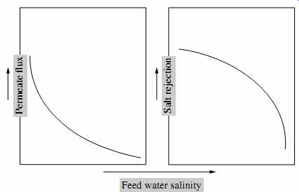
FIG. 20 Effect of salinity on RO system performance.
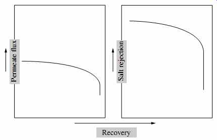
FIG. 21 Effect of recovery on RO system performance.
In terms of salt transport, an increase in feed water salinity increases the salt concentration gradient (ΔC in Eqn. 11), which results in accelerated salt transport through the membranes and therefore, in lower salt rejection (deteriorating product water quality).
6.5 Effect of Recovery on Membrane Performance
As indicated in FIG. 21, an increase in recovery results in a slow decrease in permeate flux until it reaches the point at which osmotic pressure exceeds the applied pressure and NDP is inadequate to drive flow through the membrane; at that point, freshwater flow production is discontinued.
6.6 Effect of Temperature on Membrane Performance
The use of warmer water reduces saline water viscosity, which in turn increases membrane permeability. Some of this beneficial impact is reduced by the increase of osmotic pressure with temperature (see Eqn. 1). However, the overall impact of temperature for most membranes is typically beneficial (FIG. 22). As a rule of thumb, the permeate flux increases by 3% for every 1°C of temperature increase. Because most RO membranes are made of plastic materials (polymers), warmer temperatures result in a loosening up of the membrane structure, which in turn increases salt passage (i.e., deteriorates permeate water quality).
It should be pointed out that, as seen in FIG. 22, the rate of permeate flux gain is typically much higher than the rate of deterioration of product water quality. For source water temperatures up to 30°C (86°F), using warmer water allows reduction of the feed pressure and energy used for desalination. Because of the negative impact of temperature on osmotic pressure, operation at higher temperatures may or may not be beneficial. In addition, the use of warmer water accelerates biological fouling, which in turn also reduces membrane permeability.
As discussed previously, operating conventional spiral-wound RO membranes at temperatures above 40°C (104°F) accelerates the compaction of the membrane support layer and is undesirable because it results in a premature and irreversible loss of membrane permeability. Most membrane suppliers recommend that the temperature of the source water processed by RO membranes should be maintained below 45°C (113°F) at all times to avoid permanent membrane damage.
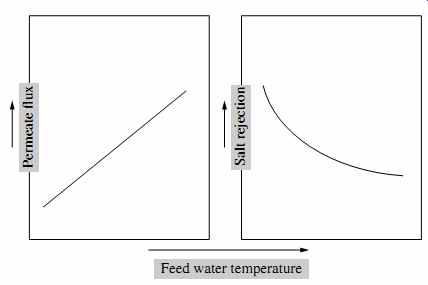
FIG. 22 Effect of temperature on RO system performance.
6.7 Effect of Feed Pressure on Membrane Performance
As can be seen from analysis of Eqn. 14, membrane flux (productivity) increases along with operating feed pressure at the same source water salinity and temperature. This occurs because the increase of feed pressure results in a proportional increase of the net driving pressure through the membrane ( FIG. 23).
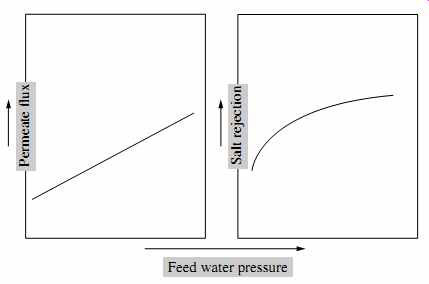
FIG. 23 Effect of feed pressure on RO system performance.
As per Eqn. 15, salt transport is unaffected by pressure. However, because more water is produced at higher pressure and the same amount of salt is contained in this water, the permeate salinity concentration decreases (i.e., it appears that salt rejection increases) with pressure.
6.8 Effect of Permeate Back Pressure on Membrane Performance
An analysis of Eqn. 14 indicates that permeate pressure (often also referred to as permeate back pressure) has a direct negative impact on flux. However, if the pressure on the permeate side of the membrane is increased, this increase will result in a reduction of the diffusion rate through the membrane and therefore of ß. Since practical experience shows that reduction of ß and the osmotic pressure is higher than the direct decrease of flux the overall effect of permeate back pressure is positive, i.e., membrane flux could be increased by operating at elevated back pressure up to a point where ß approaches 1.1. Creating additional back pressure beyond this point would have a negative impact on plant performance. The amount of permeate back pressure is limited by the impact this pressure can have on the thin film-if the pressure is higher than 0.3 bar (4.3 lb/in2 ), then it may cause delamination of the thin-film membrane layer.
7. Key Membrane Desalination Plant Components
7.1 General Overview
As with any other natural water source, seawater contains solids in two forms: suspended and dissolved. Suspended solids occur in the form of insoluble particles (particulates, debris, marine organisms, silt, colloids, etc.). Dissolved solids are present in soluble form (ions of minerals such as chloride, sodium, calcium, magnesium, etc.).
At present, practically all RO desalination plants incorporate two key treatment steps designed to sequentially remove suspended and dissolved solids from the source water. The purpose of the first step-source water pretreatment-is to remove the suspended solids and prevent some of the naturally occurring soluble solids from turning into solid form and precipitating on the RO membranes during the salt separation process.
The second step-the RO system-separates the dissolved solids from the pre treated source water, thereby producing fresh low-salinity water suitable for human consumption, agricultural uses, and for industrial and other applications.
Once the desalination process is complete, the freshwater produced by the RO sys tem is further treated for corrosion and health protection and disinfected prior to distribution for final use. This third step of the desalination plant treatment process is referred to as post-treatment.
FIG. 24 presents a general schematic of a seawater desalination plant. In general, brackish water desalination plants incorporate similar source water treatment steps and technologies. The differences between the two types of plants are discussed in detail in the next sections of this guide.
The plant shown in FIG. 24 collects water using open ocean intake, which is conditioned by coagulation and flocculation and filtered by granular media pretreatment filters to remove most particulate and colloidal solids, and some organic and microbiological foulants. The filtered water is conveyed via transfer pumps through micron size filters (referenced on the figure as cartridge filters) into the suction headers of high-pressure pumps. These pumps deliver the filtered water into the RO membrane vessels at a net driving pressure adequate to produce the target desalinated water flow and quality.
The reverse osmosis vessels are assembled in individual sets of independently operating units referred to as RO trains or racks. All RO trains collectively are termed the reverse osmosis system. The RO system usually has energy recovery equipment that allows it to reuse the energy contained in the concentrate for pumping of new source water into the membrane system.
The permeate generated by the RO trains is stabilized by addition of lime or con tact with calcite and by the addition of carbon dioxide to provide an adequate level of alkalinity and hardness for protection of the product water distribution system against corrosion. The conditioned water is stored and disinfected prior to delivery to the final users.
The particulate solids removed from the source water by the pretreatment filters are collected in the filter backwash and further concentrated by thickening and dewatering for ultimate off-site disposal to a sanitary landfill. While this solids handling approach is adopted by many of the most recently built desalination plants, in some older facilities the concentrate and backwash water are mixed and disposed to the water body used for source water collection.
7.2 Plant Intake
Plant intake is designed to collect source water at a quality and quantity adequate to produce the target volume and quality of desalinated water. Sections 6, 7, and 8 discuss various types of intakes, pump stations, and screening facilities used in seawater and brackish water desalination plants and provide guidelines for their selection and design.
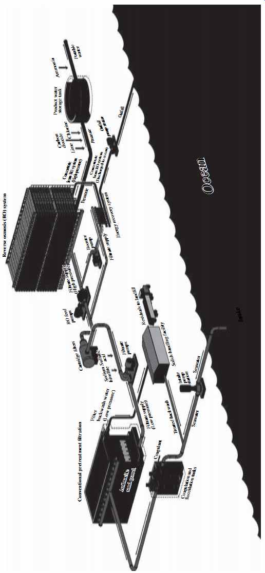
FIG. 24 Schematic of a typical seawater desalination plant.
7.3 Pretreatment
The fine microstructure of thin-film composite membranes presently used for desalination by reverse osmosis does not permit passage of particulates contained in the source water or formed during the desalination process. Therefore, if they are present in the source water in significant amounts, these particulates may cause membrane fouling, which in turn may rapidly decrease membrane productivity and result in performance failure of the desalination plant. Membrane foulants are typically organic and inorganic colloids and particulates, naturally occurring in the source water or generated on the surface of the membranes by marine microorganisms or physical-chemical processes that occur during reverse osmosis salt separation and concentration.
The purpose of the pretreatment system is to adequately and effectively remove foulants from the source water and to secure consistent and efficient performance of the downstream reverse osmosis membranes. The pretreatment system is typically located downstream of the desalination plant's intake facilities and upstream of the reverse osmosis membrane system.
Depending on the source water quality, this system may consist of one or more water treatment processes, including screening, chemical conditioning, dissolved air flotation or gravity clarification, granular media filtration, membrane microfiltration or ultra-filtration, and cartridge filtration. Section 9 of this guide addresses commonly used source water conditioning processes. Section 10 discusses sand removal, sedimentation, and dissolved air flotation clarification; sections. 11, 12, and 13 provide detailed overview of alternative pretreatment filtration technologies.
7.4 Reverse Osmosis Separation System
The key components of the RO separation system include filter effluent transfer pumps, high-pressure pumps, reverse osmosis trains, energy recovery equipment, and the membrane cleaning system. These facility components are discussed in detail in Section 14.
7.5 Post-Treatment
Post-treatment facilities include equipment for re-mineralization and disinfection of RO permeate. Some brackish water plants have additional post-treatment facilities for removal of odorous gases naturally contained in the source water, such as hydrogen sulfide. Alternative post-treatment technologies are addressed in detail in Section 15.
7.6 Desalination Plant Discharge Management
Desalination plants typically generate source water pretreatment and concentrate waste streams, which have to be handled in an environmentally safe and cost-effective manner. Section 16 describes the most commonly used desalination discharge management alternatives and provides guidance for their implementation.
8. References
American Water Works Association, Manual of Water Supply Practices, M46, Reverse Osmosis and Nanofiltration, 2nd ed., American Water Works Association, Denver, Colorado, 2007.
Fritzmann, C., J. Lowenberg, T. Wintgens, and T. Melin, "State-of-the-Art of Reverse Osmosis Desalination," Desalination, 216 (X), 1-76, 2007.
Greenlee, L. F., D. F. Lawler, B. D. Freeman, and B. Marrot, "Reverse Osmosis Desalination: Water Sources, Technology, and Today's Challenges," Water Research, 43 (X), 2317-2348, 2009.
Hassan, A., N. Ali, N. Abdull, and A. Ismail, "A Theoretical Approach on Membrane Characterization: The Deduction of Fine Structural Details of Asymmetric Nanofiltration Membranes," Desalination, 206 (X), 107-126, 2007.
Hoek, E. M. V., S. Bhattacharjee, and M. Elimelech, "Effect of Surface Roughness on Colloid Membrane DLVO Interactions," Langmuir, 19 (X), 4836-4847, 2003.
Hoek, E. M. V., and G. Agarwal, "Extended DLVO Interactions between Spherical Particles and Rough Surfaces," Journal of Colloid and Interface Science, 298 (1), 50-58, 2006.
Malaeb, L., and G. M. Ayoub, "Reverse Osmosis Technology for Water Treatment: State of the Art Review," Desalination, 267 (X), 1-8, 2011.
Wilf, M., L. Awerbuch, C. Bartels, M. Mickley, G. Pearce, and N. Voutchkov, The Guidebook to Membrane Desalination Technology, Balaban Desalination Publications, L'Aquila, Italy, 2007.
Prev. | Next
Home Similar
articles top
of page