AMAZON multi-meters discounts AMAZON oscilloscope discounts
<< cont'd from part 1
Maintenance and Repair of Wear Rings
Although most users specify wear rings on newly installed pumps, this is not economically justified as long as the pumps are designed for future installation of wear rings. When they can be utilized, deepwell turbine pump components are economical and readily available both as complete bowl assemblies and as spare parts. Leading manufacturers will furnish machining dimensions, in a format such as FIG. 14. When these pumps require service the impeller wear surfaces can be turned to a predetermined diameter and the bowls machined to receive wear rings of matching dimensions. Original clearance is restored by installing only one wear ring per stage. These machining and assembly operations are no more costly than the removal of case and impeller wear rings and the installation of new ones. Significant savings can be achieved by reduction of spare parts inventories.
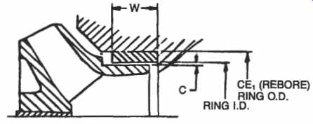
FIG. 14. Wear ring repair dimensions.
As is the case with bowl bearings, the wear rings have differential pressure across them and will act to some degree as bearings provided that they are not grooved. Grooved wear rings should only be used in installations where the product contains abrasive material. We acknowledge, however, that some users report acceptable results from the use of grooved wear rings in nonabrasive services as well.
Replacement Impellers
Comparison testing has shown that replacement impellers which are not furnished by the pump manufacturer can be very expensive in the long run. In addition to potential shortening of pump life between repairs, inadequate NPSH performance, improper curve shape and invalidation of pump warranties, the cost of additional power can be significant. In one well documented case (Reference 5) the power requirement increased from 134.7 horsepower to 139.8 horsepower resulting in an estimated additional electric power cost of $3,000 per year. Although the cost of purchasing the replacement impeller from the pump manufacturer may be greater, economic analysis will show that purchasing the impeller from another source is false economy. Some pump users have purchased impellers from others because delivery time from the pump manufacturer was too long. The problem of delivery time can be avoided by anticipation of the requirement and timely placement of the order, or by handling of the order on a rush basis by the manufacturer.
Impeller Dynamic Balance
The dynamic balance must be restored prior to reinstallation if any work has been done on an impeller or if it shows appreciable wear. Impellers which are out of balance can cause vibration and rapid wear of bearings and wear rings.
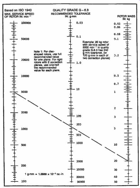
FIG. 15. Balance tolerance diagram for rotor mass up to 50 kilograms.
Vertical pump impellers normally are balanced individually to quality grade G-6.3 as indicated on the nomograms FIG. 15 for impellers which weigh 50 kilograms (1 10 pounds) or less and FIG. 16 for impellers which weigh more than 50 kilograms. By alignment of the pump operating speed in rpm with the impeller weight in kilograms, the tolerance or allowable unbalance in gram-millimeters is given by the center scale on each nomogram. The weight in kilograms equals 0.454 times weight in lbs, i.e., a 100 lb impeller weighs 45.4 kilograms. To convert the allowance in gram-millimeters to inch-ounces, multiply the value in gram-millimeters by .00139 to get the value in inch-ounces, i.e., an allowance of 100 gram-millimeters equals an allowance of 0.139 inch-ounces.
1. The impeller is mounted on a mandrel for balancing.
2. If it has a keyway, a key or half key must be installed.
3. Correction of unbalance is achieved by removal of metal from the impeller shrouds, generally by grinding with a handheld portable grinder (Figures 17 and 18).
4. Metal should not be removed from the outer 0.5 in. of the shroud, and no more than 1/3 of the shroud thickness should be removed.
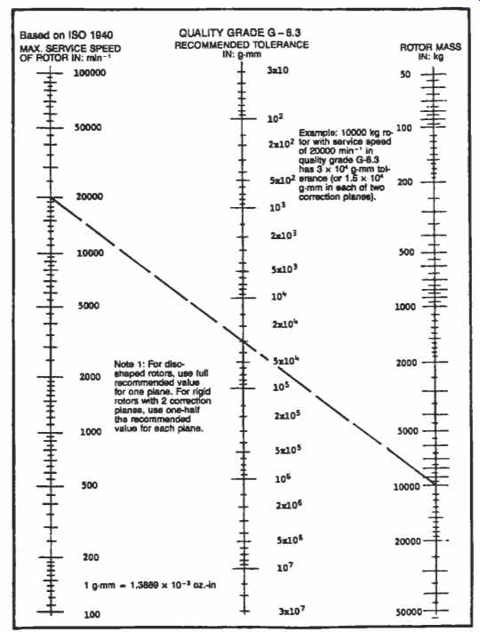
FIG. 16. Balance tolerance nomogram for rotor mass above 50 kilograms.
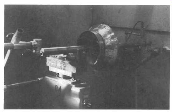
FIG. 17. Impeller on dynamic balancing machine. (Byron Jackson Pump Division,
Borg-Warner Industrial Products, Inc.)
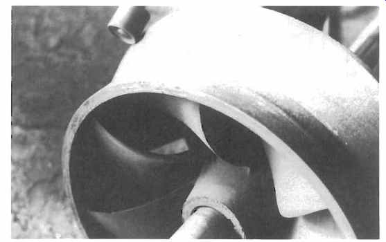
FIG. 18. Correcting unbalance by removal of metal from the impeller shroud.
(Byron Jackson Pump Division, Borg-Warner Industrial Products, Inc.)
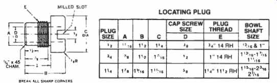
FIG. 19. Dimensions for shaft locating plug.
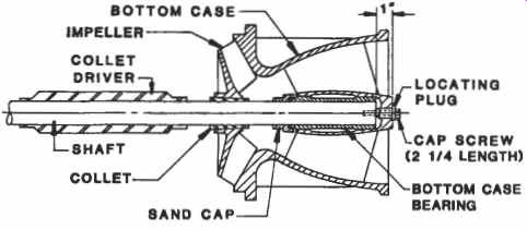
FIG. 20. Shaft position for collet installation.
Mounting of Impellers on the Shaft
The use of collets is a common and satisfactory method for mounting impellers on the shafts of small vertical turbine-type pumps, generally limited to pumps with bowl outside diameters less than 18 in. and shaft diameters less than 2 3/16 in. The collets are split along me side, have an inside diameter equal to the diameter of the shaft and are taped on the outside to fit €he tapered bore of the impeller. When clean, free from nicks and scratches and properly driven into the impeller bores, collets will lock the impellers in place axially and radially, and will transmit the torque from the shaft to the impellers. They are quite satisfactory for small process pumps, but should not be used for temperatures above 160°F.
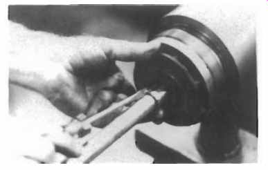
FIG. 21. Using a screwdriver to keep the collet from binding on the shaft.
(Byron Jackson Pump Division, Borg-Warner Industrial Products, Inc.)
To drive the collets into the impeller bores properly, the shaft should be positioned firmly in the bottom case with a shaft locating plug and capscrew.
1. FIG. 19 shows typical dimensions for the shaft locating plug.
2. FIG. 20 shows the assembly of the shaft locating plug into the bottom case. The shaft is held in place by a 2.25 in. long capscrew installed in the tapped hole at the bottom of the shaft. Prior to assembly all parts including the collet driver must be inspected to be sure that they are clean and free from nicks, burrs or scratches.
3. The impeller is positioned against the bottom case. The collet is then inserted in the impeller bore. Collets usually close in on the bore and tend to grab the shaft, so a screwdriver is inserted to open the collet and allow it to slide along the shaft, as shown in FIG. 21. Next, the collet driver is slipped over the shaft with the large diameter end facing the collet.
4. The collet is then driven firmly into the impeller bore utilizing the impact of the collet driver. Hold the impeller tightly against the case by hand while driving the collet. Let go of the collet driver before impact and allow its momentum to drive the collet (FIG. 22).
5. Check the impeller to be sure that it is tight on the shaft.
6. The collet driver impact can loosen the 2.25 in. long capscrew. Retighten it after each impeller is mounted.
7. Additional series cases and impellers are installed until the bowl assembly is complete. As an added precaution the capscrew can be released and the shaft rotated after each stage is assembled to be sure that there is no binding.
8. The 2.25 in. long capscrew and the locating plug must be removed when the bowl assembly is complete.
Never use heat or a pin, dowel or setscrew to install or reposition a collet-mounted impeller.
An alternate method of securing the impeller to the shaft uses a key to transmit the torque and an axial locking device, such as a snap ring or split ring, to locate the impeller axially and transmit axial thrust from the impeller to the shaft. Split rings are superior. If snap rings are used, they should be confined so that impeller thrust does not make them tend to pop out of the snap ring groove. The fit between the impeller and the shaft should be a snug sliding fit.
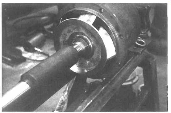
FIG. 22. Collet driver in position to drive a collet. (Byron Jackson Pump
Division, Borg-Warner Industrial Products, Inc.)
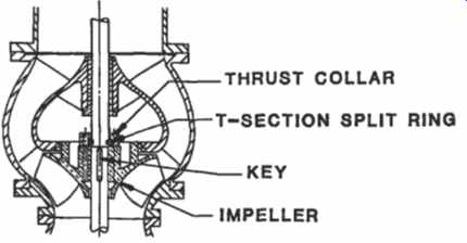
FIG. 23. Impeller mounted with key and T-section split ring with thrust
collar.
For multi-stage pumps with semi-open impellers, correct sizing of split rings is essential to ensure maximum pump efficiency and trouble-free operation. Original split rings are individually sized at the factory during pump assembly to precisely locate the impellers. Used split rings, when reused, must be installed only with the same impellers, and in their original location and orientation. Always use new split rings whenever the pump shaft, cases or impellers are replaced. Machine new split rings to size, or verify the correct sizing of used split rings, as follows:
1. T-section split rings with thrust collars are shown in FIG. 23.
2. When feasible, assemble the pump bowl assembly in a vertical position to assure the most accurate split ring sizing. During horizontal assembly, be sure to support pump shaft and cases adequately to prevent any sagging, which could lead to alignment errors.
3. With first-stage of pump assembled, install a locating plug and capscrew as shown in FIG. 20 through the hole in the bottom of the suction bell or bottom case and into the pump shaft. Tighten the capscrew to locate the rotating element during assembly of the second stage. If the first-stage impeller is closed and the series impellers are semi-open, place a spacer, such as a piece of key stock, between the first-stage impeller and the impeller case or suction bell. This will raise the impeller the distance recommended by the manufacturer, generally 1/4 in. Then tighten the capscrew. (Be sure to remove these parts after the pump bowl assembly is completed.)
4. Slip the second-stage impeller down the pump shaft until it bottoms against the first stage case.
5. Accurately measure distance "B" from the face of the impeller hub to the nearest edge of the split ring groove, as shown in FIG. 24a. This can be done by putting key stock in the groove and measuring the gap with a feeler gauge.
6. Machine one side of split ring, as shown in FIG. 24b, to "By' + .002 in. This side will install toward the impeller. Mark the OD of the split ring in two places 180" apart so that both halves will be marked after the ring is cut in half. This is to assure correct orientation at assembly.
7. Next, turn the split ring around and place it against the thrust collar with (backwards orientation), as shown in FIG. 24c. Machine so that the protrusion of the split ring beyond the thrust collar is .002 to .004 in.
8. After machining to size, saw-cut the new split ring in half, with a saw-cut width of approximately 1/32 in., and deburr.
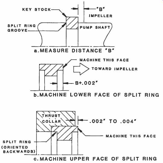
FIG. 24. Sizing of T-section split ring.
9. Repeat Steps 4 through 8 to size the split rings for each succeeding stage.
10. When the pump bowl assembly has been completed, remove the capscrew and locating plug, and the spacer for the first-stage impeller, if used. Note: Some pump designs utilize shims to position the impellers so that remachining of the split rings is not necessary. Figures 25 through 27 show further details.
Maintenance and Repair of Shafts
Most vertical multistage pumps have wearing surfaces on the shaft under the bowl bearings, bottom bearings, column bearings, tension nut bearings and packing. If the impellers are collet mounted there is very little machining labor in the shaft, and worn shafts generally are replaced rather than repaired. Unless provided with shaft sleeves, worn line shafts are turned end for end to provide new journals when line shaft bearings are replaced. Large shafts or shafts with extensive machining can be built up using hard chrome plating or metalizing. A grinding operation then assures that the shaft is round, smooth and within tolerance prior to reinstallation.
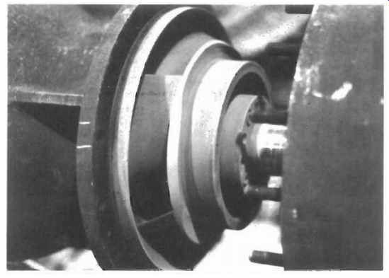
FIG. 25
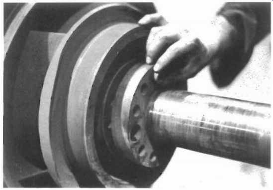
FIG. 26. Removing the thrust collar. (Byron Jackson Pump Division, BorgWarner)
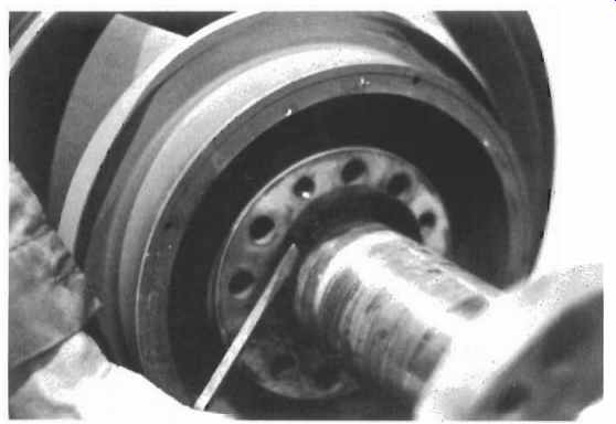
FIG. 27. Removing the split ring. (Byron Jackson Pump Division, BorgWarner
Industrial Products, Inc.)
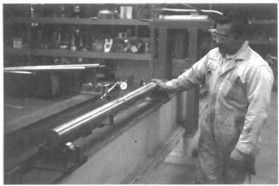
FIG. 28. Checking shaft straightness. (Byron Jackson Pump Division, BorgWarner
Industrial Products, Inc.)
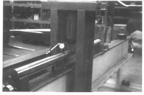
FIG. 29. Straightening a shaft. (Byron Jackson Pump Division, Borg-Warner
Industrial Products, Inc.)
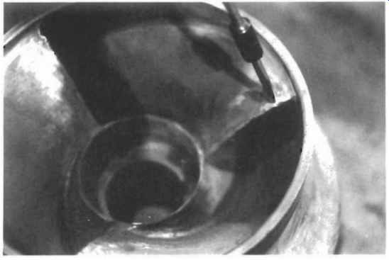
FIG. 30. Minor cavitation damage in an impeller eye. (Byron Jackson Pump
Division, Borg-Warner Industrial Products, Inc.)
All shafts must be checked and straightened if necessary prior to reinstallation. Straightening is performed at ambient temperature using a hydraulic press or arbor press. The supports used to hold the shafting during the straightening operation are generally "V" blocks with brass or copper inserts, but some small shafts are straightened on the rollers used to measure runout.
Straightening Sequence
1. Rotate the shaft on rollers located near each end of the shaft and check the runout total indicator reading (T.I.R.) at several points along the shaft using a dial indicator. See FIG. 28.
2. Move the shaft onto the "V" blocks and straighten by applying force with a hydraulic press or arbor press. See FIG. 29.
3. Check T.I.R. Maximum acceptable T.I.R. is .0005 in. per ft of shaft length, but not more than BO1 in. within any one ft of length.
4. If T.I.R. is acceptable, except for deepwell pump shafts, thermal treat in a furnace to relieve peak residual stresses in accordance with Table 2. Thermal treatment must be performed vertically with the shaft hanging so that gravity tends to keep it straight.
5. Check T.I.R. after thermal treatment. If T.I.R. is unacceptable repeat Steps 1 through 4 until T.I.R. is acceptable.
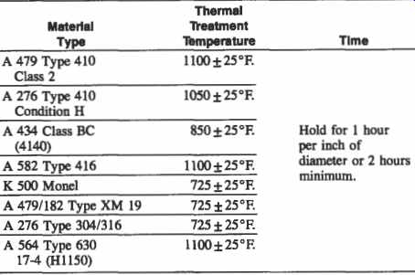
Table 2 Thermal Treatment of Shafting after Straightening
Turned ground and straightened vertical pump line shaft material is readily available. However, this shafting may not be straight when received due to handling and shipment and should be checked when received. The standard material is Type 416 stainless steel, which contains approximately 12 percent chromium, has good strength and adequate corrosion resistance for most applications.
Table 3A Materials Guidelines from API Standard 610
Table 38 Material Specifications from API Standard 610
Upgrading of Materials
A generally accepted guide for selection of materials used in centrifugal pumps for process services is contained in API Standard 610, and reproduced as Tables 3A and 3B. Minor damage (see FIG. 30) is to be expected. However, if excessive corrosion, erosion, wear, or breakage is observed in a particular pump, the materials of construction should be reviewed and upgraded to these standards. If unacceptable maintenance costs exist even though the guidelines have been followed, materials should be further upgraded, substituting for example 12 percent chrome steel for low carbon steel or 18-8 stainless steel for 12 percent chrome steel to solve corrosion problems. Wear rings can be overlayed with Stellite or Colmonoy for better wear resistance. Shafts can be upgraded from Type 416 stainless steel to Type 440 heat treated stainless steel if more strength is required but corrosion resistance is satisfactory.
If both increased strength and corrosion resistance are needed 17-4 PH, XM-19 or K 500 Monel shafting can be substituted (Table 4). XM-19 offers a good combination of strength, corrosion resistance and cost. If collet-mounted impellers have proved to be unsatisfactory in a particular service, and a change to keyed impellers is made, it may be necessary to upgrade the shaft material to compensate for the stress raisers created by cutting keyways and split ring grooves in the shaft. For additional information on materials, refer also to Appendix 1A in section 1 of this volume.
Graphalloy Bearings
Product lubricated bearings in clean liquids can be upgraded to a material such as Graphalloy. Graphalloy is a solid carbon graphite, the pores of which have been impregnated with molten metal in a high heat and high pressure process. During the impregnation process the metal permeates the graphite in long continuous metal filaments. It is these filaments which give Graphalloy its ductility, high strength and good heat dissipating properties. The metal increases its strength and ductility and removes heat generated at the bearing surface. Graphalloy contains no oil and does not produce any toxic emission which may contaminate the pumped product. It is extremely durable in clean products. Graphalloy bearings operate well at temperatures from -50°F to +300"F in fresh or salt water, gasoline, jet fuels, solvents, bleaches, caustics, dyes, liquefied gases, acids and most chemical process and transfer services. Babbitt grade GM105.3 is generally recommended for pump bearings. However, Graphalloy is not recommended for applications in products containing abrasive material. In products with abrasive material, extremely hard bearings such as tungsten carbide, boron carbide, or Tribal09 can be utilized running on a hard journal. However, some of these materials are extremely brittle, and cannot be externally shrink fitted.
Table 4 Typical Mechanical Properties of 1 in. Diameter Shaft Stock
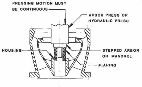
FIG. 31. Pressing Graphalloy bearing into housing using arbor press or
hydraulic press.
Installing Graphalloy Bearings
The preferred method for installing Graphalloy bearings utilizes an arbor press or hydraulic press as shown in FIG. 31. The bearing or the bore into which the bearing is installed should have a 1/32 in. minimum X 45 degr.chamfer to facilitate entry of the bearing. A stepped mandrel or arbor should be used to ensure that the bearing will be positioned straight with the hole before installation. The small outside diameter of the arbor should be 1/16 in. smaller than the inside diameter of the bearing, and the large outside diameter of the arbor should be larger than the outside diameter of the bearing. The pressing motion must be continuous with no interruption until the bushing is completely in place. As an alternative, the bearing may be pressed into the housing by the bolt-and-nut method; that is, with a plate against the upper end of the bushing as shown in FIG. 32. The nut must be continuously drawn up.
Threaded Fasteners
Except in a passive environment such as refined petroleum products, studs and nuts are preferred to capscrews. The threaded fastener material should be resistant to any corrosion that may be present and should be upgraded if corrosion is observed.
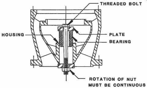
FIG. 32. Bolt-and-nut method of pressing Graphalloy bearing into housing.
All threads should be examined before reinstallation to ensure that no burrs, nicks or bad threads exist. Imperfect threaded fasteners must be replaced or the threads "chased" with a thread die. All threads both internal and external must be cleaned with solvent to remove all foreign matter including rust and old thread lubricant. Apply a uniform layer of thread lubricant Dag Dispersion No. 156 or equal with a friction coefficient of 0.15 to all surfaces that experience relative motion, including threads, nuts, washers, and flanges in contact with nuts or washers. If these procedures are used the torque values indicated in Table 5 may be applied to the materials shown in Table 6.
Care of Large Threaded Joints
Threaded line shaft couplings are common in deepwell pumps and small circulators. The threads on the shaft are cut with great care to assure concentricity with the centerline of the shaft. Threads must be carefully inspected before assembly. Shaft ends must be wiped clean and inspected to be sure that they are free from foreign matter, burrs, nicks, and scratches. Thread compound should be used. The two shafts each are threaded approximately halfway into the coupling and the ends of the two shafts firmly butted together. It has been suggested that a Teflon@ disk can be installed between shaft ends to compensate for some misalignment. This is a questionable practice. Line shaft couplings are designed so that a substantial amount of the torque is transmitted by friction through the shaft ends. Lubrication of the shaft ends by Teflon@ can cause the coupling to break.
Table 5 Torque Values for Threaded Fasteners
Table 6 Mechanical Properties of Common Threaded Fastener Materials
Pipe wrenches are normally used to assemble the line shaft. One wrench is applied to the shaft above the coupling and one on the coupling. Care must be exercised to avoid side strain on the shaft when locking the joint.
Pipe wrenches must not be used on the shaft below the coupling as assembly of bearings, impellers, and collets will include sliding these parts down over this portion of the shaft. Strap wrenches are suitable for this purpose and are preferable. The use of pipe wrenches on shafting, although quite appropriate for servicing deepwell pumps, should be discouraged, because this practice easily could carry over to the servicing of process pumps where it is completely unacceptable. Threaded line shaft couplings always have left hand threads that tend to be tightened by the transmitted torque.
Threaded inner column generally has left hand threads because right hand threads would tend to loosen from the torque applied as the result of a bearing failure. The threads are internal and straight, not external and tapered like pipe threads. This is shown in FIG. 4. The joints are sealed by the metal-to-metal contact between the smooth ends of the column. It therefore is necessary to avoid nicks, scratches, or burrs on the ends of the column. The threads should be coated with a thread lubricant or a thread sealant. Inner column may be tightened with pipe wrenches, strap wrenches, or chain tongs.
Threaded outer column and bowl assemblies generally are tightened with chain tongs. The threads are external, right hand and straight, not tapered. This is also shown in FIG. 4. These joints also are sealed by metal-to-metal contact between the ends of the column. Column and bowl threads should be coated with a thread lubricant or a thread sealant.
Submersible pump column has tapered external pipe threads that must be coated with a thread sealant and tightened both to seal the joints and to keep them from loosening from the starting torque. The threaded bowl joints and the joint between the cast iron top case and the steel column should be cleaned with Loctite Primer T and coated with Loctite 277.
The Loctite 277 joints may require heat for disassembly.
Care of Flanged Pressure Joints
Flanged mating surfaces must be thoroughly cleaned prior to reassembly and sealing surfaces inspected to be sure that they are free from burrs, nicks, or scratches. Static seals such as O-rings, flat gaskets, and spiral-wound gaskets should not be reused but should be replaced after each dismantling of the pressure joint. Additional information on static seals is contained in section 7 of Volume 1. After installation of the static seal, assemble the joint hand tight and check for uniform gap or metal-to-metal contact of the flange mating surfaces. Tighten bolts alternately in pairs 180" apart, then another pair 90" clockwise from the first pair, and so forth until the entire flange has been tightened. The bolt-tightening sequence for a 12 bolt flange is shown in FIG. 33. Bolts should be tightened in three steps, 113 torque, 213 torque, and full torque.
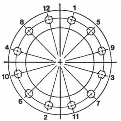
FIG. 33. Bolt tightening sequence.
Handling
The crane, shackles, eye bolts, cable, and other lifting devices must be in good repair and capable of safely handling the weights. The crane should be positioned so that the hook is directly over the center of gravity of the piece to be lifted. Do not bump, push, or scrape components or assemblies. Motor, turbine, or gear lifting lugs or eye bolts are designed for lifting these components only. Do not lift the pump together with the motor, turbine, or gear. Use lifting lugs when provided. Otherwise, install eye bolts with washers and nuts in the flange bolt holes and attach lifting lines. Use care to avoid damage to the machined surfaces.
Tools and Work Area
Common millwright and pipe-fitter tools generally are sufficient to perform vertical pump maintenance. The work area should be clean and well lighted. Horizontal racks for dismantling and reassembly of vertical turbine type pumps are desirable to avoid handling damage, and to shorten turnaround time.
Personnel
Maintenance personnel should be familiar with the basic principles of vertical pumps and know how to handle the tools required for their maintenance and repair. Leading pump manufacturers have highly qualified service engineers who can visit periodically and assist in the training and updating of maintenance personnel with the latest techniques. Some manufacturers also have service training centers where maintenance personnel can receive up-to-date instruction on vertical pump maintenance.
Spare Parts
Economical repair and maintenance procedures require adequate availability of the necessary spare parts. Pump repair parts are classified according to anticipated use:
Level 1
parts required for inspection of the pump during a scheduled shutdown. This includes gaskets, O-rings, bearings, and packing or mechanical seal.
Level 2
Parts replaced because of normal wear of the pump over a period of time. During normal operation, pump wearing clearances open up, causing less efficient operation and higher susceptibility to failure. In addition to this, wear rings and shaft sleeves are required.
Level 3
Parts required for overhaul in the event of a pump failure include all parts listed above plus a pump shaft and impellers. Stocking of a complete bowl assembly will minimize pump downtime and allow for an orderly and economical repair.
In process plants, Level 3 stocking of spare pump parts is justified for most vertical pumps. The general topic of spare parts is covered in section 5 of Volume 1 of this series.
Service Records
The topic of Maintenance Records is covered in section 6 of Volume 1 of this series.
Problem Solving
Detailed information relating to vertical pump problem solving is contained in Reference 6; for general troubleshooting matrixes consult Volume 2 of this series.
Installation and Operation
Installation guidelines may vary greatly for the various vertical pump types and the reader should consult the manufacturer for details.
PREV. | NEXT | Article Index | HOME