AMAZON multi-meters discounts AMAZON oscilloscope discounts
The justification for using a reciprocating pump in a petrochemical plant
instead of a centrifugal or rotary pump must be cost-not just the initial cost
but total cost, including costs for power and maintenance.
Some applications are inherently best suited for reciprocating units.
Such services include high-pressure water cleaning (typically 20 gpm at 10,000 psig), glycol injection (typically 5 gpm at 1,000 psig), and ammonia charging (typically 40 gpm at 4,000 psig). Another application that practically mandates a reciprocating unit is abrasive and/or viscous slurries above about 500 psig. Examples of these services range from coal slurry to peanut butter.
The best feature of the power pump is its high efficiency. Overall efficiencies normally range from 85 to 94 percent. The losses of approximately 10 percent include all those due to belts, gears, bearings, packings, and valves.
Another characteristic of the reciprocating pump is that capacity is a function of speed, and is relatively independent of discharge pressure.
Therefore, a constant-speed power pump that moves 100 gpm at 500 psig will handle very nearly 100 gpm at 3,000 psig.
The direct-acting pump has some of the same advantages as the power pump, plus others. These units are well suited for high-pressure low flow applications. Discharge pressures normally range from 300 to 5,000 psig, but may exceed 10,000 psig. Capacity is proportional to speed from stall to maximum speed, regardless of the discharge pressure.
Speed is controlled by throttling the motive fluid. The unit is normally self-priming-particularly the low clearance-volume type.
Direct-acting pumps are negligibly affected by hostile environments such as corrosive fumes, because of the absence of a bearing housing, crankcase, or oil reservoir (except for units requiring a lubricator). Some direct-acting pumps inadvertently inundated by flood-water have continued to operate without adverse effects. Direct-acting pumps are quiet, simple to maintain, and their low speeds and rugged construction lead to a very long life.
Both power and direct-acting pumps with special fittings and operating at low speeds have been successfully applied to abrasive-slurry services.
The low thermal efficiency of the direct-acting pump is sometimes used to advantage. When steam is the motive fluid, very little heat is lost from inlet to exhaust. The exhaust temperature is the same as that obtained by throttling. In those cases where high-pressure steam is throttled to a lower pressure for heating (such as for deaerating boiler feedwater), the steam can be used to drive a direct-acting pump, with the exhaust steam used for heating. In this circumstance, the drive end (piston rings, valves, etc.) is made to operate without lubrication, so that the exhaust steam will be oil-free.
Pump Classification
Reciprocating pumps are usually classified by their features:
Drive end, i.e., power or direct-acting.
Orientation of centerline of the pumping element, i.e., horizontal or vertical.
Number of discharge strokes per cycle of each drive rod, i.e., single-acting or double-acting .
Configuration of the pumping element, i.e., piston plunger or diaphragm.
Number of drive rods, Le., simplex, duplex, or multiplex.
FIG. 1 illustrates this classification in chart form.
FIG. 2 shows two examples of reciprocating pumps.
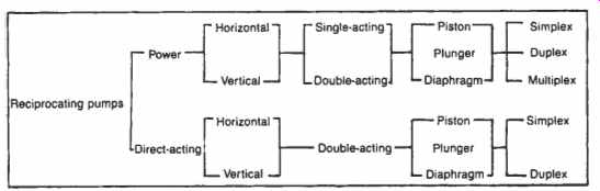
FIG. 1. Classification of reciprocating action pumps.
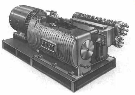
FIG. 2A. Horizontal, quintuplex, power pump.
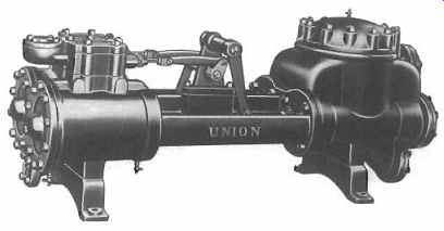
FIG. 2B. Direct-acting, duplex, double-acting piston pump. (Reciprocating
pumps may be driven by electric power or a motive fluid.) Union Pump Company.
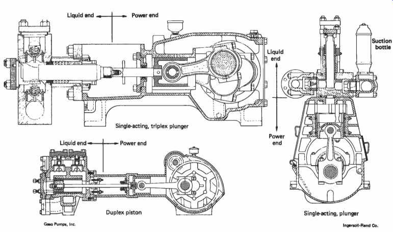
FIG. 3 Power pump styles.
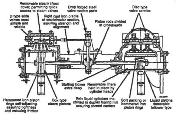
FIG. 4 Typical action of a horizontal duplex pump.
Cross-sectional drawings for power and direct-acting pumps are shown in FIGs 3 and 4, respectively.
The size of a power pump is normally designated by listing first the diameter of the plunger (or the piston), and second the length of the stroke. In the United States, the units are inches. For example, a pump designated as 2 X 3 has a plunger diameter of 2 in, and a stroke length of 3 in. For a direct-acting pump, the same convention is followed, except that the diameter of the drive piston precedes the liquid-end-element diameter. For example, a pump designated 6 X 4 X 6 has a drive-piston diameter of 6 in., a liquid-piston diameter of 4 in., and a stroke length of 6 in.
Liquid-End Components
All reciprocating pumps contain one or more pumping elements pistons, plungers, or diaphragms) that reciprocate into and out of pumping chambers to produce the pumping action. Each chamber contains at least one suction and one discharge valve. The valves are simply check valves that are opened by the liquid differential pressure. Most valves are spring loaded.
The liquid end is that portion of the pump that does the pumping. Elements common to all reciprocating-pump liquid ends are the liquid cylinder, pumping element, and valves.
The liquid cylinder is the major pressure-retaining part of the liquid end, and forms the major portion of the pumping chamber. It usually contains or supports all other liquid-end components.
A piston ("a," FIG. 5) is a flat cylindrical disk, mounted on a rod, and usually contains some type of sealing rings. A plunger ("b," FIG. 5) is a smooth rod and, in its normal configuration, can only be single acting. With a piston, the sealing elements move. With a plunger, they are stationary. A piston must seal against a cylinder or liner inside the pump. A plunger must seal only in the stuffing box, and touches only packing and possibly stuffing box bushings.
A piston pump is normally equipped with a replaceable liner (sleeve) that absorbs the wear from the piston rings. Because a plunger contacts only stuffing box components, plunger pumps do not require liners.
Sealing between the pumping chamber and atmosphere is accomplished in a stuffing box or packing box ("c," FIG. 5). The stuffing box contains rings of packing that conform to and seal against The stuffing box ID and the rod.
If a lubricant, sealing liquid or flushing liquid is injected into the center of the packing, a lantern ring or seal cage is required. This ring provides an annular space between the packing rings so that the injected fluid can freely flow to the rod surface.
The valves in a reciprocating pump are opened by the liquid differential pressure, and allow flow in only one direction. They have a variety of shapes, including spheres, hemispheres, disk, and bevel seats (FIG. 6).
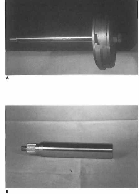
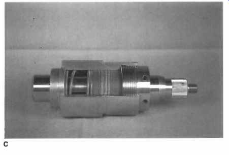
FIG. 5. Steam piston mounted on rod (a). Plunger with hard metal coating
(b). Cutaway stuffing box showing spring-loaded packing (c). (Union Pump Company.)
Packing Maintenance
The biggest maintenance problem on most reciprocating pumps is packing. Although the life of standard packing in a power pump is about 2,500 hr, some installations with special stuffing box arrangements have experienced a life of more than 18,000 hr, at discharge pressures of up to 4,000 psig.
Short packing life can result from any of the following conditions:
1. Improper packing for the application.
2. Insufficient lubrication.
3. Misalignment of plunger (or rod) with stuffing box.
4. Worn plunger, rod, stuffing box bore or stuffing box bushings.
5. Packing gland too tight or too loose.
6. High speed or high pressure.
7. High or low temperature of pumpage.
8. Excessive friction (too much packing in box).
9. Packing running dry (pumping chamber gas-bound).
10. Shock conditions arising from entrained gas or cavitation, broken or faulty valve springs, or system problems.
11. Solids from the pumpage, environment or lubricant.
12. Improper packing installation or break-in (where required).
13. Icing caused by volatile liquids that refrigerate and form ice crystals upon leakage to atmosphere, or by pumping liquids at temperatures below 32°F.
As is evident from these conditions, short packing life can indicate problems elsewhere in the pump or system.
To achieve a low leakage rate, the clearance between the plunger (or rod) and packing must be essentially zero. This requires that the sealing rings be relatively soft and pliant. Because the packing is pliant, it tends to flow into the stuffing box clearances, especially between the plunger and follower bushing. If this bushing does not provide an effective barrier, the packing will extrude, and leakage will increase.
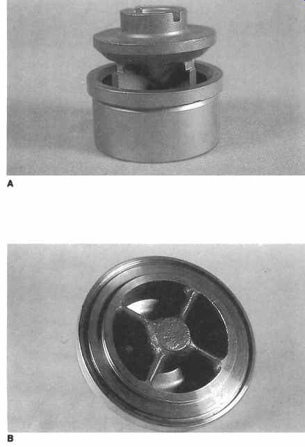
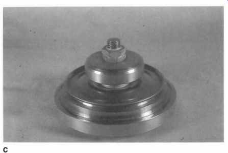
FIG. 6. Wing guided valve and seat pressed into cylinder (a). Disk-type
valve and seat clamped to cylinder (b). Disk-valve assembly (c). (Union Pump
Company.)
A set of square of V-type packing rings will experience a pressure gradient, during operation, as indicated in FIG. 7. The last ring of packing adjacent to the gland-follower bushing will experience the largest axial loading of all rings-resulting in greater deformation, tighter sealing and, therefore, the largest pressure drop. Hence, the gap between the plunger and the follower bushing must be small enough to prevent packing extrusion. Most packing failures originate at this critical sealing point.
Because this last ring of packing is the most critical, does the most sealing, and generates the most friction, it requires more lubrication than do the others. In the nonlubricated arrangement (FIG. 7), this ring must rely on the surface of the plunger to drag some of the pumpage back to it in order to provide cooling and lubrication. To maximize packing life in this situation, the overall stack height of the packing should not exceed the stroke length of the pump. Short packing life has resulted from nonlubricated operation of stuffing boxes equipped with lantern rings, especially on short-stroke pumps (approximately 2 in. stroke length). The lantern ring located in the center of the packing sometimes causes the overall stack height of the packing to exceed the stroke length.
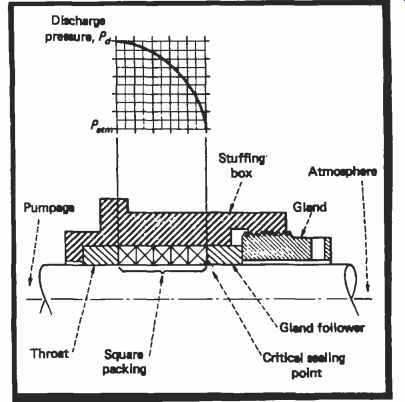
FIG. 7
Because the last ring of packing requires more lubrication than do the others, lubrication of the packing from the atmospheric side is more effective than injection of oil into a lantern ring located in the center of the packing. Care must be exercised to get the lubricant onto the plunger surface and close enough to the last ring, so that the stroke of the plunger will carry the lubricant under the ring. If the lubricant drips onto the plunger aft of the gland, the plunger-stroke length may not be sufficient to carry the lubricant under the last ling of packing.
Because the last ring of packing deforms the most, it conforms to the irregularities in the bore of the stuffing box. Therefore, when the gland is tightened, most of the force is absorbed in the last ring, causing it to seal tighter in the box and on the plunger. Very little of the gland force gets transmitted to the inner rings of packing.
Hence, the bottom ring of packing must be firmly seated during installation, using a rod with a flat end or a stack of gland bushings. After the stuffing box has been completely assembled, with the plunger reinstalled, and before filling the liquid end with fluid, it is advisable to tighten the gland snugly by hand with the gland wrench. If allowed to sit with this imposed load, most packing will flow and conform to the stuffing box and plunger. It will often be found that after 10 minutes the gland can be further tightened. This process should be repeated two or three times, or until the gland cannot be further tightened. The gland should then be completely loosened, and the packing allowed to expand for 10 to 15 minutes. The gland should then be drawn up only finger tight (no wrench). Now, the block valves may be opened and liquid allowed into the pump.
Soaking the packing in oil prior to installation will enhance a proper break-in and increase packing life.
During the first few hours of pump operation following repacking, each stuffing box should be monitored for temperature. It is normal for some boxes to run warmer than others--as much as 50°F above the pumping temperature. Only if this exceeds the maximum temperature rating of the packing are steps required to reduce box temperature.
The best lubricant for most installations equipped with stuffing box lubricators has been found to be steam-cylinder oil. This oil is compounded with tallow, which gives it a tenacity for the plunger surface and makes it ideal for providing a lubricating wedge between the plunger and packing.
The concepts that a higher discharge pressure requires more rings of packing and that a larger number of rings lasts longer may have been true for long-stroke low-speed machines but has been disproven in some power-pump applications. Unless they are profusely lubricated, the larger number of rings create additional frictional heat and wipe lubricant from the plunger surface-thus depriving some rings of lubrication. On numerous salt-water injection pumps operating at pressures above 4,000 psig, packing life was reported to be only two weeks when twelve rings of packing were installed in each stuffing box. With three rings in each box, packing life was approximately six months.
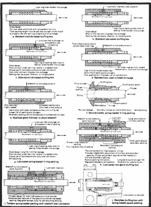
FIG. 8. Stuffing box designs.
Stuffing Boxes
Stuffing box designs-including the standard nonlubricated types and various lubrication and bleed off schemes to minimize leakage and extend packing life-are shown in FIG. 8.
The most significant advance in packing arrangements in recent years is the spring-loading of packing. Although the concept has been discussed in the literature for decades, and actually put into practice by one manufacturer for at least twenty years, only recently has this arrangement received general attention.
Spring loading is applied almost exclusively to V-ring (chevron) packing but also works well with square packing rings. The spring must always be located on the pressure side of the packing. Springs of various types can be used, including a single large coil, multiple coil, wave washer, belleville, and a thick rubber washer.
The force required by the spring is small compared to the force imposed on the packing by the liquid. The major function of the spring is to provide a small preload to help set the packing, and to hold all bushings and packing rings in place during operation.
Spring loading of packings has many advantages. It: Requires no adjustment of the gland-the gland is tightened until it bottoms, then is locked. This removes one of the biggest variables in packing life-operator skill.
Allows expansion--if the packing expands due to frictional heat during the initial break-in, the spring allows for the expansion.
Takes up wear-as the packing wears, adjustment automatically occurs from inside the box. The problem of transmitting the force through the top packing ring during gland adjustment is eliminated.
Provides a cavity--the spring cavity provides an annular space for the injection of a clean liquid for slurry applications.
Eliminates the need for gland if pump design allows this-the stuffing box assembly (if a separate component) can be disassembled and reassembled on a workbench.
Disadvantages of spring-loaded packing are associated with the cavity created by the spring. Since this cavity communicates directly with the pumping chamber, the additional clearance volume can cause a reduction in volumetric efficiency if the pumpage is sufficiently compressible. This cavity also provides a place for vapors to accumulate. If the pump design does not provide for venting this space, a reduction in volumetric efficiency may occur.
Spring-loaded packing is the reciprocating pump's equivalent to the mechanical seal for rotating shafts. Leakage is low, life is extended, and adjustments are eliminated. Packing sets can be stacked in tandem (they must be independently supported) for a stepped pressure reduction, or to capture leakage from the primary packing that should not be allowed to escape to the environment.
Plunger Material
After the packing, the plunger is the component of a power pump that requires the most frequent replacement. The high speed of the plunger and the friction load of the packing tend to wear the plunger surface.
For longer life, plungers are sometimes hardened. A more popular method is to apply a hard coating to the plunger surface. Such coatings are of chrome, various ceramics, nickel-based alloys, or cobalt-based alloys. Desired features for the coatings include hardness, smoothness, high bond strength, corrosion resistance, and low cost. No one coating optimizes all of these features.
The ceramic coatings are harder than the metals but are brittle, porous, and sometimes lower in bond strength. Porosity contributes to shorter packing life. Mixing of hard particles such 'as tungsten carbide into the less-hard nickel or cobalt alloys has resulted in longer plunger life at the expense of shorter packing life.
Drive-End Components
The drive end of a power pump is called a power end (see FIG. 3). Its function is to convert rotating motion from a driver to reciprocating motion for the liquid end. The main component of the power end is the power frame, which supports all other power end parts and, usually, the liquid end. The second major item in the power end is the crankshaft (sometimes, a camshaft). The function of the crankshaft in a power pump is the same as a crankshaft in an internal-combustion engine, except that the flow of energy is opposite.
The main bearings support the shaft in the power frame. The correcting rod is driven by the throw of the crankshaft on one end, and drives a crosshead on the other. The crosshead moves in pure reciprocating motion, the crankshaft in pure rotating motion. The connecting rod is the link between the two.
Although similar in construction and motion to a piston in an internal combustion engine, the crosshead is fastened to a rod called an "extension,'' "stub," or "pony" rod. The other end of this rod is fastened to the plunger or piston rod.
The function of the drive end (or steam end, or gas end) of a direct-acting pump is to convert the differential pressure of the motive fluid to reciprocating motion for the liquid end. The drive end is similar in construction to the liquid end, containing a double-acting piston and valving.
The major difference is that the valve is mechanically actuated by a control system that senses the location of the drive piston, to cause the valve to reverse the flow of the motive fluid when the drive piston reaches the end of its stroke.
The main component of the drive end is the drive cylinder. This cylinder forms the major portion of the pressure boundary, and supports the other drive-end parts. Unlike the power-pump's power end, this cylinder does not support the liquid end.
Maintenance of Liquid Ring Vacuum Pumps
Liquid ring vacuum pumps and compressors consist of a rotor with radial pumping vanes rotating in a casing, causing a ring of service liquid to form at the outer circumference of the rotor. Depending on the machine manufacturer, the rotor may be mounted with its rotational axis eccentric to the casing centerline, or concentric in a lobe-shaped casing.
This allows the service liquid depth in the vanes to change depending on the rotational position of the vanes. This in turn causes a liquid piston effect with the cavities between successive vanes being filled and emptied of service liquid as the rotor turns. Porting in the casing is arranged so that the suction flow enters the rotor where the liquid ring depth is decreasing, and discharge occurs when the depth is nearing its maximum.
The service liquid, vanes, and close-running clearances at the rotor ends serve to seal the compression "chambers." As the depth of the service liquid increases, the "chamber" volume decreases and compresses the gases. High pressure ratios are obtained by staging. FIGs 9A and 9B illustrate the liquid ring principle.
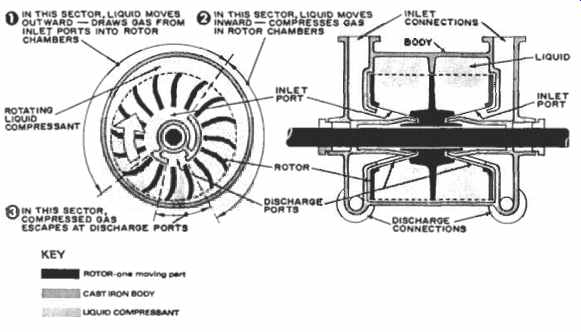
FIG. 9 A. Sectional and end view of a liquid ring vacuum pump. (Nash Engineering
Company.)
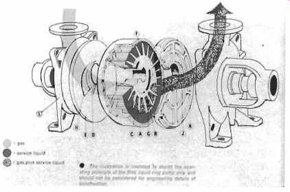
FIG. 9 B. Exploded view of a liquid ring vacuum pump with side ports.
(SIHI.)
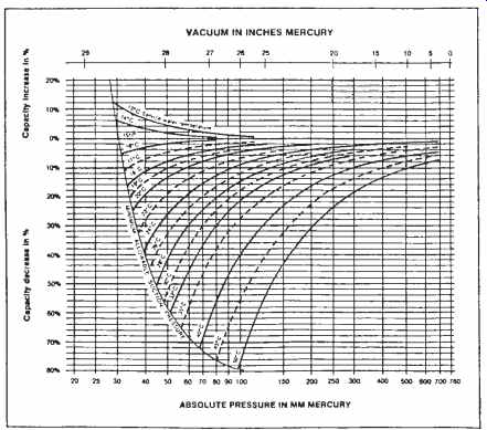
FIG. 10. Performance reduction of a liquid ring vacuum pump due to service
water temperature rise. (SIHI.)
Several clearances are critical to the successful operation of liquid ring machines. Rotor end clearances provide a leakage path from discharge back to suction where they are not filled with service liquid. Where suction and discharge ports are arranged in cones around the shaft, the clearances between the cones and the rotor are important for the same reason.
The rotor tip clearance in the casing is less critical since this will be submerged in service liquid.
Also important is the service water temperature rise which can have an effect on the performance of liquid ring vacuum pumps. FIG. 10 is typical of this interaction.
The importance of rotor end clearances in most designs necessitates particular care in rotor axial positioning while assembling, and attention to bearing fits so that the rotor cannot change position other than by thermal growth. This becomes more difficult, but equally important in multistaged machines. During operation of the machines, bearing care is important to ensure that the rotor does not shift. Adequate lubrication and vibration, shock pulse and/or spike energy monitoring is important. Most liquid ring machines employ tight running clearances over fairly large areas (Le., the entire rotor end area at both ends). Bearing failures resulting in axial or radial position changes can result in rubs and seizure of the machines. Assembly views reveal the close running tolerances employed ( FIGs 11 and 12).
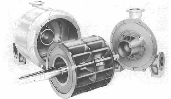
FIG. 11. Disassembled view of liquid ring vacuum pump with side ports
showing "sandwich" construction.
Sealing of shafts is accomplished by either mechanical seals or by packing. Double and tandem seals may be used where process conditions dictate it. Close attention to the maintenance of flushing and buffer fluid systems is necessary to ensure long life of the seals. Seal failure can result in significant reduction in vacuum pump capacity with no visible external leakage.
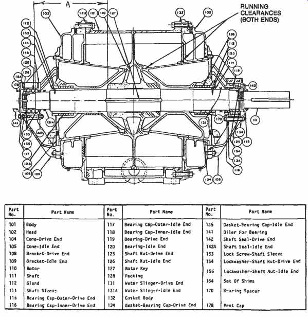
FIG. 12. Cross section and bill of material of a vacuum pump with cone
type porting. (Nash Engineering Company)
Performance of liquid ring machines can be significantly affected by the service liquid used. The volume of liquid employed alters the submergence of the rotor vane tips throughout the compression cycle and will affect the volume of gas drawn into the machine and the compression ratio, Service liquid absorbs the heat of compression and must be cooled.
This is accomplished by running the liquid through external coolers, or by make-up liquid, or by using a once-through system. Usually the service liquid circulating system employs a discharge vessel in which gas and liquid separation occurs. The level of liquid in this vessel is maintained at the level of the shaft centerline to ensure the correct amount of liquid is in the machine.
As mentioned, service liquid temperature also has a profound effect on the efficiency and capacity of liquid ring machines. As the temperature of the service liquid rises, so does its vapor pressure. This increases the partial pressure of the service liquid vapor in the machine and reduces the volume available for the process gas.
Final discharge pressure, where it can vary, can also affect overall performance. If the process gas contains a condensable vapor and the discharge pressure is high enough at compression temperatures to allow condensation, some liquid will condense. When this liquid leaks through running clearances back to suction, it can flash off and reduce inlet or suction capacity.
Starting of liquid ring machines must be done with the machine only half full of liquid. Failure to maintain the correct level for starting can result in either reduced capacity (level too low) or overloading (level too high). The latter is more serious as it can result in driver overload, belt wear, or coupling failure. These machines have only a limited capability to handle liquids in the process stream.
Large volumes of liquid in the process gas or vapor stream can overload the machine. The reader will appreciate that a volume of liquid greater than the volume between vanes at the discharge openings cannot be compressed. High vibration, overload, and machine failure can result.
Particulate matter or solids in the process stream can be handled in small quantities. Solids can lodge between running faces and cause wear, and eventually open up clearances to reduce capacity. Large quantities of solids can plug up internal clearances and passages, reducing the capacity of the machine and possibly seizing it. Excess heat can be generated by the closing up of running clearances. This can cause excess thermal growth of the rotor and further wear.
Cavitation damage can often be found in the suction porting and on vacuum pump rotors. During operation this can be detected by the characteristic sound of "gravel on steel." Some vacuum pump systems employ an ejector in their suction lines to boost the suction pressure that the machine sees. Motive fluid for the ejector can be taken from the pump discharge. Where cavitation is found it may be worthwhile to consider the use of a suction line ejector, raising the suction pressure (where process conditions will allow), or using pump parts made of materials resistant to cavitation damage, such as high-chrome steels.
Maintenance of liquid ring machines is minimized because there are no wearing parts other than bearings and seals. The bulk of necessary maintenance efforts should be aimed at the service water, seal fluid, and pressure regulating systems. This necessitates careful monitoring by operating personnel. In addition to these it is necessary to monitor bearing health by vibration analysis, shock pulse, or spike energy methods.
When disassembly for repairs is necessary there are very important details to ensure that running clearances are reestablished correctly. In machines with cone type inlet and discharge porting, axial rotor position is critical, especially where running clearances are on tapered surfaces as in FIG. 13. You can appreciate that an axial shift will close up the clearance on one end and open it up on the other. In FIG. 13 the thrust end bearing is on the left hand side. Shimming is used at this end under the bearing cap to adjust the axial position. When machines of this design are disassembled, note the shim thickness removed. If the entire rotor assembly is being replaced, compare the distance marked "A" on the new and the old rotor and adjust the shim thickness accordingly.
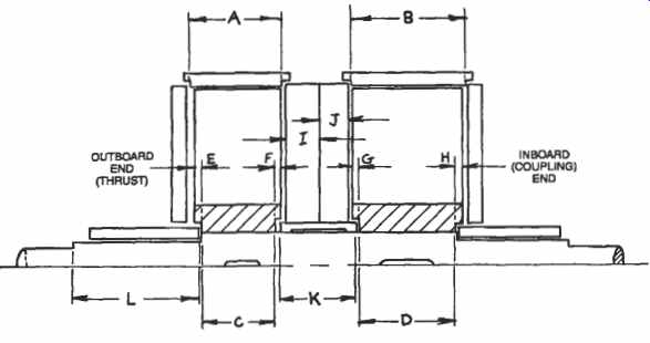
FIG. 13. Clearance checks required for vacuum pump rotors.
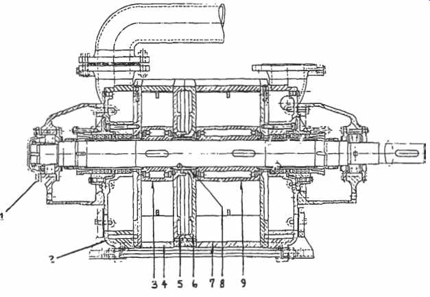
FIG. 14. Cross section view of two-stage vacuum pump.
In "sandwich" construction machines such as in FIG. 14, the correct clearances are more difficult to obtain. A two-stage machine with thrust end at the left is shown, Several measurements are required to ensure correct assembly (refer to FIGs 13 and 14).
1. The length of the center bodies "A" and "B" (items 4, 7).
2. The length of the impeller hubs "C" and "D" (items 3, 9).
3. Check that the impeller ends are parallel and the tips .03 to .08 mm (.001 to 0.003 in.) narrower than the hubs.
4. The depths of the recesses at the impeller hubs "E," "F," "G," and "H."
5. Check that the surfaces of the intermediate plates (items 5, 6) are parallel and flat within 0.04 mm (0.0015 in.) and record their thickness at the outer circumference "I," and "J."
6. The length of the distance bushing "K" (item 8) and ensure that its ends are parallel within 0.03 mm.
7. The distance from the inboard end of the sleeve to the first shaft step outboard of the sleeve at the thrust bearing end of the rotor "L." The clearances that will result from assembly can now be calculated, and adjustments made:
Total End Clearance = (A + B + I + J) (E + C + K + D + H)
Total Center Clearance = (K F G) (I + J)
On a typical machine, these clearances should be .38 to .51 mm (.015 to .020 in.) per running surface pair. To adjust the center clearances it is necessary to machine the center distance bushing (alter "K"). To adjust the end clearances it is necessary to machine the impeller ends. If impeller ends are damaged by a rub they must also be machined. If impeller machining results in excess end clearances it will be necessary to machine the center bodies. The limit of impeller machining before center body machining is necessary is typically .76 mm (.030 in.). When one impeller is shortened it is also necessary to shorten the other impeller by an amount equal to the amount taken off the first impeller multiplied by the ratio of impeller lengths in order to maintain the original pressure ratio.
When impellers and center bodies are shortened, the internal volume of the machine, and hence capacity, is reduced. To restore the original capacity it will be necessary to purchase and install new impellers and center bodies.
The distance L is critical to ensure that the entire assembly is located at its correct axial position. Reassembly begins with the rotating element and intermediate plates. Start by assembling the thrust end shaft sleeve to the shaft with its locknut and washer, setting "L" to the original dimension. Stack up the rotor parts in order, including the intermediate plates and finishing with the other sleeve locknut. This is most easily accomplished with the rotor standing on its thrust end. Check the clearance of the intermediate plates to the impeller ends with feeler gauges. The body can now be assembled, again beginning at the thrust end. Start with the cover (item 2 in FIG. 14). Use either O-rings or Permatex at the body joints during this assembly. Insert the rotating assembly with the intermediate plates when the first center body is installed. Finish this step of the assembly with the other end cover and tie rods. With the body on its feet, level the assembly and tighten the tie rods evenly to the recommended torque values.
Finally, assemble the bearing brackets, bearings and seals or packing.
Assemble the thrust end first. At the driven end the bearing must be centralized in its housing. Check the end float by loosening and tightening the thrust end bearing cover (item 1 in FIG. 14). Measure axial movement with a dial indicator on the exposed shaft end. Adjust that bearing cover so that the rotor will be held in the middle of its axial float.
PREV. | NEXT | Article Index | HOME