AMAZON multi-meters discounts AMAZON oscilloscope discounts
Types of Vertical Pumps for Process Plants
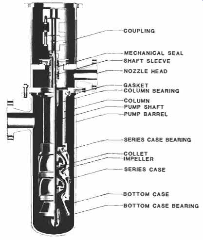
FIG. 1. Multistage process or condensate pump. (Byron Jackson Pump Division,
Borg-Warner Industrial Products, Inc.)
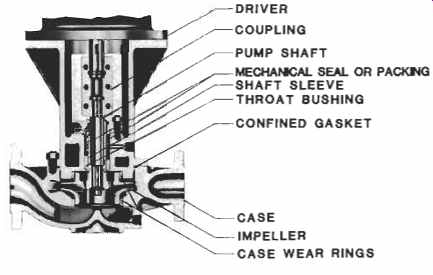
FIG. 2. Inline process pump. (Byron Jackson Pump Division, Borg-Warner
Industrial Products, Inc.)
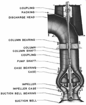
FIG. 3. Vertical circulating pump. (Byron Jackson Pump Division, BorgWarner
Industrial Products, Inc.)
The types of vertical pumps most commonly used in process plants include multistage process and condensate pumps, single stage inline process pumps, cooling water and cooling tower circulating pumps, and deepwell pumps. The multistage process and condensate pumps as illustrated in FIG. 1 utilize standardized diffuser bowl assemblies installed in an outer barrel that is under suction pressure. This type of pump is often used where the available NPSH is not sufficient to accommodate a horizontal pump, or where space is at a premium. The first stage impeller is located below foundation level, thus providing additional NPSH. Reference 1 classifies these as vertical canned pumps of the double-casing type. Double casing refers to the type of construction in which the pressure casing is separate and distinct from the pumping element it contains. The single stage inline process pump shown in FIG. 2 is simple, and pipe strain has minimal impact on rotating element alignment. This type of pump is selected when low initial cost of the pump, foundation, and piping is especially significant, and sufficient NPSH is available. Cooling water and cooling tower circulating pumps as shown in FIG. 3 take suction from an open pit, sump, lake, river, or ocean. They provide cooling water to process units and to steam generating plant condensers. A typical deepwell pump is shown in FIG. 4. As the name implies, it pumps water from deep wells and is used to supply makeup and utility water to process plants in areas where the water table and water supply permits. Submersible pumps as illustrated in FIG. 5 supply makeup and utility water from wells that are either too deep for reliable operation of deepwell pumps with line shafts or in locations that for environmental reasons require underground discharge installations. They also are used where motor noise would be a problem, and in locations subject to flooding.
Types of Drivers
Most vertical pumps in process plants are driven by vertical electric motors. The process pumps often have spares, driven by vertical steam turbines. Pumps driven through right angle gears by horizontal electric motors, steam turbines, or internal combustion engines are less common.
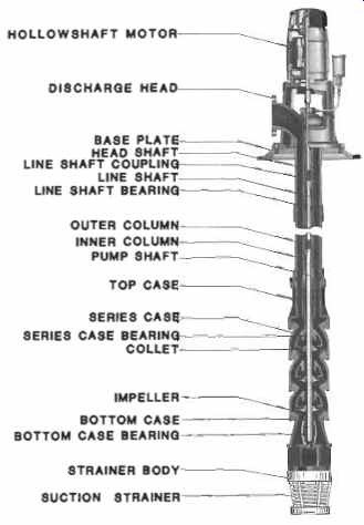
FIG. 4. Deepwell pump. (Byron Jackson Pump Division, Borg-Warner Industrial
Products, Inc.)
Solid Shaft Drivers
Solid shaft drivers are used to drive pumps with relatively short shafts, less than 30 to 50 ft long. They therefore are used to drive almost all process pumps and circulators. They provide more positive shaft alignment which is especially important when the pumps have mechanical seals rather than packing. However, when a solid shaft driver is used, the axial adjustment of the pump rotor is limited by the height of the adjusting plate in the three-piece or four-piece coupling. The maximum axial adjustment is generally 1/2 to 3/4 in. Thrust bearings normally will carry either downthrust or upthrust. The construction of a solid shaft motor is shown in FIG. 6.
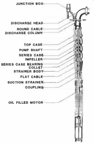
FIG. 5. Submersible pump and motor. (Byron Jackson Pump Division, Borg
Warner Industrial Products, Inc.)
Hollow Shaft Drivers
Hollow shaft drivers provide a means to adjust the axial position of the pump rotor for distances of several inches. They were developed many years ago to fill the need for large adjustments created by the demand for deepwell pumps of ever increasing settings, and are now standard for almost all deepwell pumps. Hollow shaft drivers normally are designed to carry downthrust only and special provisions must be made if upthrust capability is required. The construction of a hollow shaft motor is shown in FIG. 7.
Deepwell Pump Shaft Adjustment
Details of the upper portion of a hollow shaft motor are shown in FIG. 8. To adjust the axial position of a deepwell pump rotor:
1. Tighten the adjusting nut until the shaft starts to turn. This is an indication that the shaft has stretched to compensate for the weight of the rotor and that the impellers have lifted clear of the bowls.
2. Engage the locking arm or otherwise hold the self release coupling against rotation. As the coupling is keyed to the shaft, the shaft is also held against rotation.
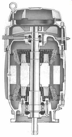
FIG. 6. Totally enclosed fan-cooled vertical solid shaft normal thrust
motor. (US Electrical Motors Division, Emerson Electric Company.)
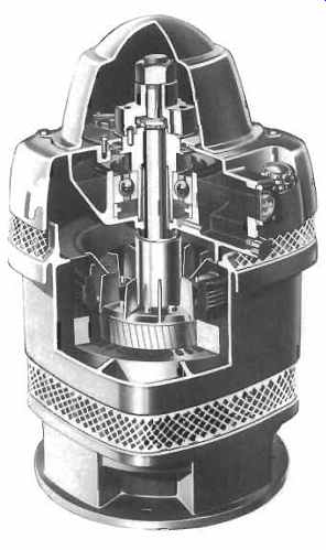
FIG. 7. Weather-protected type I (WPI) vertical hollow shaft high thrust
motor. (US. Electrical Motors Division, Emerson Electric Company.)
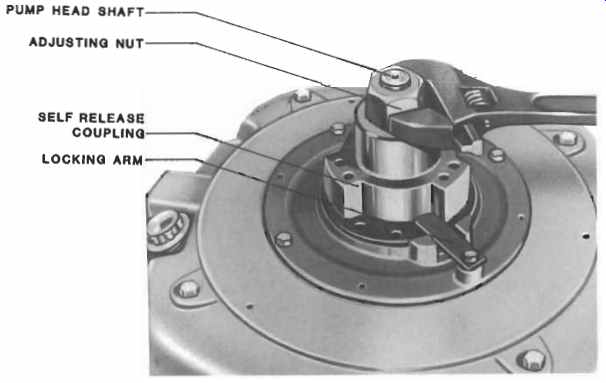
FIG. 8. Deepwell pump shaft adjustment. (US. Electrical Motors Division,
Emerson Electric Company.)
3. Tighten the adjusting nut to lift the pump rotor the distance recommended by the pump manufacturer to compensate for shaft stretch caused by pump thrust and to allow proper running clearance. Recommended rotor lift is generally given on the pump nameplate or in the instruction manual. For pumps with semi-open impellers the running clearance is only a few thousandths of an inch. For pumps with closed impellers a typical running clearance is 1/4 in. Shaft stretch caused by pump thrust will vary considerably from pump to Pump.
4. A typical adjusting nut design provides four tapped holes in the self release coupling, three drilled holes in the adjusting nut, and 12 threads per in. With this design, the shaft can be locked in place by installation of the locking screw in any 1/12 turn position, and the shaft setting will be within 1/14 or .007 in.
5. Disengage the locking arm.
An alternate method to set semi-open impellers is:
1. Raise the rotor as high as it will go, then lower it two turns on the adjusting nut. While raising the rotor, do not use excessive force.
Especially if the impellers are collet mounted, be sure that they are not pushed downward. Just raise the rotor until a very slight drag is detected when the shaft is rotated.
2. Lock the adjusting nut, start the pump, record the ammeter reading with the pump running at or near shutoff or at the minimum flow allowed by the system.
3. Check to be sure that the ammeter reading is less than the amps on the motor nameplate.
4. Lower the rotor 1/12 turn, lock the adjusting nut, start the pump, record the ammeter reading with the pump running at or near shutoff or at the minimum flow allowed by the system.
5. Repeat Step 4 until the ammeter reading increases sharply because the impellers are rubbing on the bowls.
6. Raise the rotor 1/12 turn to its final position and lock the adjusting nut.
Hollow Shaft Driver Reverse Protection Clutch
If the driver is accidentally run with reverse rotation, the deepwell pump shaft couplings may unscrew and cause damage. FIG. 9 shows a reverse protection clutch which automatically disengages the pump shaft from the driver if this occurs. In some shallow settings, particularly with closed impellers, the pump may develop a momentary upthrust during start-up. In these installations, it is necessary to install hold-down bolts in the clutch and to check that the driver thrust bearing is locked against upthrust.
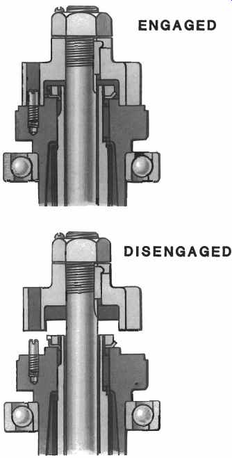
FIG. 9. Reverse protection clutch. ( U.S. Electrical Motors Division,
Emerson Electric Company.)
Hollow Shaft Driver Non-reverse Ratchet
If the foot valve or check valve fails in a deepwell pump installation, when the driver is de-energized the water will run back down the discharge column, and the pump will act as an unloaded turbine and achieve a reverse rotation that can reach rather high speed. The torque does not reverse, so the threaded couplings do not unscrew as a result. Although the reverse speed may be higher than normal pump rpm, it seldom causes damage unless water-lubricated column bearings are run dry, or an attempt is made to restart the driver while the pump is running backward.
Hollow shaft drivers are often provided with non-reverse ratchets so that reverse rotation does not occur. Alternatively, some systems have time-delay relays to prevent premature restart. For deepwell pumps with settings of 500 ft or more, the long shaft may act as a torsional spring causing the non-reverse ratchet to be subject to torque reversals. This problem is controlled by providing a ratchet which is designed so that the movement caused by torque reversal is only 3 to 5 degr.
Driver Alignment
Practically all vertical pumps now used in process plants within the United States utilize the driver thrust bearing to carry the combined thrust load of the driver and pump. The driver also provides radial alignment for the upper portion of the pump shaft. Reliability of the driver bearings is a prerequisite to the reliability of the pump. Accurate radial and angular alignment between the driver and the pump is therefore essential. Driver shaft runout and concentricity with the mounting fit must be checked prior to assembly or reassembly of the driver on the pump.
Referring to FIG. 10, the following steps are recommended:
1. Thoroughly clean the driver shaft and mounting face.
2. Attach a dial indicator to the shaft and rotate on the driver rabbet fit and mounting face.
a. The concentricity of the rabbet fit must be within 0.002 in. total indicator reading (T.I.R.) per ft of rabbet fit diameter.
b. The mounting face must be perpendicular to the shaft within 0.002 in. T.I.R. per ft of rabbet fit diameter.
3. Mount the dial indicator on the driver housing to check the shaft runout and end float.
a. The shaft runout must not exceed 0.002 in. T.I.R. or .001 in. T.I.R. per in. of shaft diameter, whichever is greater.
b. The squareness of the split ring groove to the shaft centerline must be within 0.002 in. T.I.R.
c. Shaft end float must not exceed 0.010 in. T.I.R., and 0.005 in.
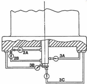
FIG. 10. Checking solid shaft driver run-outs and concentricities.
T.I.R. is preferred if the pump has a mechanical seal.
These requirements are more stringent than NEMA standards but are essential for solid shaft drivers, particularly for pumps operating at 3600 rpm or pumps with mechanical seals. NEMA tolerances for concentricities and runouts, however, are quite adequate for deepwell turbine pumps utilizing hollow shaft motors or gears and operating at 1,800 rpm or less.
Some pump manufacturers do not use the driver rabbet fit for alignment but rather align the driver shaft to the pump stuffing box, tighten the driver mounting bolts and dowel the driver to the pump. This procedure eliminates the need for concentricity between the driver shaft and rabbet fit. It can also be utilized as a compensating procedure if an otherwise acceptable driver has a rabbet fit which is not concentric with the shaft.
1. The driver rabbet fit or the driver mounting flange of the pump is machined to allow clearance for radial movement of the driver.
2. If the driver is too large to be moved radially with a soft hammer, four jacking bolts should be installed.
3. The driver is then mounted, but the mounting bolts are left loose and the driver is aligned radially using a dial indicator mounted on the shaft and sweeping the stuffing box bore. This alignment should be within .0005 in. per in. of stuffing box bore for pumps with mechanical seals and .001 in. per in. of stuffing box bore for packed pumps. If the coupling has an adjusting plate such as the four-piece coupling shown in FIG. 11, it can be unscrewed until it engages the driver half coupling or spacer to verify alignment between the pump shaft and the driver shaft.
4. The driver bolts are then tightened and two dowels installed.
5. After the coupling is completely assembled, check the runout of the pump shaft or shaft sleeve, measured by a dial indicator immediately above the stuffing box or mechanical seal. Paragraph 2.8.2.7 of Reference 1 requires that this runout not exceed .002 in. T.I.R. for new pumps operating above 1400 rpm, or .004 in. T.I.R. for new pumps operating below 1,400 rpm.
Maintenance and Repair of Driver Bearings
Except for drivers with grease lubricated ball bearings, dry sump oil mist lubrication for driver antifriction bearings is recommended. Concurrent elimination of cooling water is generally feasible. If a self-contained lube oil reservoir is required, lube oil purification is recommended. These topics are detailed in section 7 of Volume 1 of this series.
The precautions required for proper assembly and removal of ball bearings are also covered in section 7 of that volume.
Maintenance and Repair of Submersible Motors
Submersible pumping units are generally not pulled from the well until the pump performance has deteriorated by about 5 percent head loss, or the motor has burned out, or "megging" of the motor windings shows a low resistance to ground. Repair of a damaged motor should only be done by the manufacturer or by an authorized repair shop. Some manufacturers stock rebuilt motors for immediate shipment so that outage time is minimized. Instructions for the preparation of used motors for shipment must be followed with great care so that further damage is avoided.
Detailed information on the maintenance of a particular type of submersible pumping unit is contained in Reference 2.
Maintenance and Repair of Driver to Pump Couplings
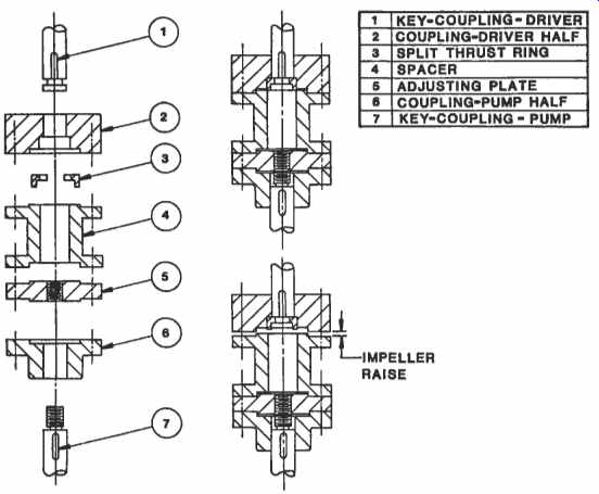
FIG. 11. Four-piece coupling.
Two piece or three piece couplings are used to connect solid shaft drivers to pumps with packed stuffing boxes and closed impellers. Three-piece couplings have threaded adjusting plates for adjusting axial impeller clearances in vertical pumps with semi-open impellers. Four piece couplings as shown in FIG. 11 are adjustable axially and have spacers so that mechanical seals may be removed without removing the drivers.
Maintenance of radial and angular alignment of all rigid couplings is extremely important. They do not normally wear but are subject to corrosion and handling damage. Except for very large couplings it is generally most economical to replace a coupling if there is time to obtain a new coupling from the pump manufacturer. Components of the two, three and four-piece couplings can be repaired to restore original concentricities and the squareness of flange faces.
1. Rabbet fits may be built up by metalizing or by careful peening with a ball peen hammer to provide stock for machining. Welding distorts the part and should be avoided.
2. Coupling hubs and spacers should be mounted on a mandrel to assure that the coupling is running absolutely true. Skim cuts are used to restore the flatness and squareness of flange faces and the concentricities of rabbet fits. Only skim cuts should be used and concentricities and tolerances must be maintained.
3. Coupling bores may be restored by chrome plating followed by an internal grinding operation. However, this is generally an expensive procedure.
4. Both the driver half coupling and the pump half coupling should be installed with snug sliding fits.
5. Large couplings or couplings operating at 3,600 RPM and above should be placed on a mandrel and dynamically balanced, using procedures similar to those used for the dynamic balancing of impellers.
Maintenance and Repair of Pump Shaft Couplings
Both threaded and keyed shaft couplings are found in circulating, deep-well, and submersible pumps. Shaft couplings are relatively inexpensive.
They should be stocked, and replaced if corrosion or damage makes them unserviceable.
Auxiliary Piping Requirements
Special attention to auxiliary piping requirements can reduce maintenance and repair costs, especially those related to barrels, seals, and packing. This is particularly true if the pumped liquid is very hot, very cold, volatile, or when the pump suction is under a vacuum or very high pressure. Reference 3 covers auxiliary piping requirements for these cases.
Maintenance and Repair of Packed Stuffing Boxes
.Almost all process pumps are equipped with mechanical seals. Packed stuffing boxes are generally found only in deepwell pumps and circulating pumps handling cold clean water or with a cold clean water injection below the packing.
1. Soft braided fabric packing impregnated with lubricant is satisfactory for low pressure applications. Lubricated synthetic packing is advisable for higher pressures.
2. Preformed packing rings promote a quicker and better packing job.
However, if the replacement packing is in a continuous coil it must be cut into rings before installing. Tightly wrap one end of the packing around the shaft or a mandrel which is the same diameter as the shaft. Wrap one coil and mark it with a sharp knife. Leave a gap of 1/16 to l/s in. and mark the ends parallel. After cutting on the marks, a length of packing may be used as a template for cutting all the other rings.
3. Remove all old packing, using flexible packing hooks. Be sure to remove the old packing below the lantern ring.
4. Check the shaft or sleeve for nicks and scratches, remove any that are present, and then clean carefully. Clean the bore of the stuffing box. Check the lantern ring to make sure that the channels and holes are not plugged.
5. Coat at least the outside diameter of each packing ring with grease or oil.
6. Place the first ring around the shaft and press it evenly to the bottom of the stuffing box. Seat it firmly against the face of the throat bushing. Rotate the shaft by hand until it turns freely. This helps provide initial running clearance. Install succeeding rings in the same manner, with each joint 90" clockwise from the preceding one. Each ring must be seated firmly as it is installed to avoid overloading the rings next to the gland which do most of the sealing. Whenever possible, use split bushings as shown in FIG. 12 to seat each ring separately. They prevent cocking and compress each ring evenly in the stuffing box. Wood, babbitt or brass bushings may be used.
When all packing rings are installed, the shaft should turn freely without binding.
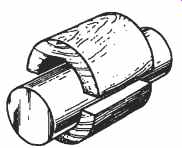
FIG. 12. Use split bushings to seat each ring of packing separately.
7. Install the packing gland and draw the gland nuts hand tight. Do not compress the packing.
8. When a pump is first operated with new packing, it should be loose enough to allow a small stream of liquid to flow from the gland.
There should be no leakage around the OD of the packing. Do not operate the pump with packing too tightly compressed, and do not make final adjustment until the pump has been operated for several hours. Then tighten the gland nuts alternately, very slowly and evenly, until the leakage rate is reduced to a steady drip. Gland nuts should be tightened 1/6 turn (one flat) at a time and the packing leakage observed for 10 minutes before tightening another 1/6 turn.
9. Check the gland temperature and loosen the gland nuts to increase the leakage rate if overheating of the packing is observed. The gland adjustment should be checked periodically and readjusted as needed.
Note: Refer also to the packing instructions in section 8 of Volume 2.
Maintenance and Repair of Pump Bearings
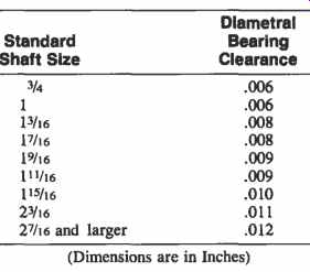
Table 1 Nominal Diametral Clearances for Vertical Pump Bearings
Table 1 shows nominal diametral clearances for vertical pump bearings. Bearings should always be made from non-galling materials or the surfaces should be nitrided or overlayed with Stellite or Colmonoy so that they are non-galling.
Bowl bearings are product lubricated and normally have sufficient differential pressure across them to provide ample flow for lubrication and cooling. The load-carrying ability of bowl bearings is enhanced by the Lomakin effect which is a function of the magnitude of the differential pressure across the bearing and is explained in detail in Reference 4. Unless the product being pumped contains foreign material, these bearings are best designed without spiral or axial grooves. Grooves interfere both with the Lomakin effect and with the hydrodynamic load carrying ability of the bearings.
Product Lubricated Column
Bearings should have spiral or axial grooves to provide proper cooling because they generally are not subject to differential pressure.
Grease Lubricated Column
Bearings should have axial grooves.
Oil Lubricated Column
Bearings should have spiral grooves to provide a downward pumping action.
Prelubrication of Column
Bearings that are installed above the water level in a deepwell or circulating pump is necessary. It can be achieved by oil or grease lube, by fresh water injection from a source other than the pump discharge, or by pre-lube piping around the check valve in the discharge piping of a deepwell pump.
The bottom case or suction bell bearings in deepwell turbine pumps and circulating water pumps are usually lubricated by a heavy non-water-soluble grease which when installed in a properly designed bearing housing with a large grease reservoir will last until the pump needs to be dismantled for other reasons (FIG. 13). These bearings should be inspected and repacked during routine maintenance. The bearing grooves and grease reservoir should be filled completely and the grease plug reinstalled so that the bearing is dead-ended and the grease will not wash out.
Tension nut bearings should have oil or grease lubrication or injection of pumped product that has been passed through a filter or a cyclone separator. Cyclone separators are inexpensive and reliable, provided that no large solid particles are in the product, there is a large density difference between the liquid and the solids, and the orifice does not erode out.
Avoidance of Wear Rings
Semi-open impeller designs should be utilized whenever possible so that wear rings are avoided. If wear ring repair costs are excessive, complete bowl assemblies of closed-impeller construction may be replaced by semi-open impeller bowl assemblies after design review by the pump manufacturer. This review should include determination that the driver thrust bearing is adequate and that the coupling can be replaced with one that is axially adjustable. The initial efficiency of semi-open impeller units can be up to two points higher because of reduced disk friction and more accurate and better finished water passages. The high efficiency can be sustained by periodic axial adjustment of the rotor without dismantling the pump. Closed impellers are necessary, however, when pumping hot liquids, because of the axial thermal expansion of the pump, and generally when the pumps are more than 100 ft in length.
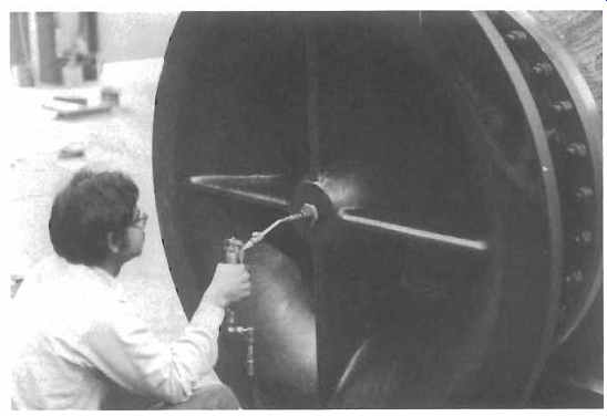
FIG. 13. Greasing a suction bell bearing. (Byron Jackson Pump Division,
Borg-Warner Industrial Products, Inc.
PREV. | NEXT | Article Index | HOME