AMAZON multi-meters discounts AMAZON oscilloscope discounts
<< cont. from part 1
Detailed Inspection Procedures
There are several basic rules that should be observed when inspecting and repairing process pumps. Some of these are:
1. Have a good understanding what clearances and fits should be met.
2. Record all data and measurements on suitable inspection forms.
Record all unusual deterioration found while dismantling the pump.
3. Use new gaskets and O-rings when reassembling the pump.
4. Keep the work place clean.
Inspection of Parts Shafts
1. Check for straightness: Runout is not to exceed 0.002 in. Bearing seats must be in good condition.
2. Inspect threads, keyways, and shoulders on shaft. Repair if damaged.
3. Measure and record all shaft fits. Undersized or damaged fits should be repaired by the procedures outlined in Volume 3 of this series.
Case End Wall and Cover
1. Measure and record all fits between pump casing and mating parts.
2. Remove all plugs and fittings to inspect threads. Reinstall all plugs and fittings.
3. Inspect and indicate mounting pads to ensure they are flat and parallel with pump centerline. Machine, if out of alignment.
Bearing Housing and Bearings
1. Observe good anti-friction bearing mounting procedures (see Volume 3 for details).
2. Ball bearings: Replace if worn, loose, or rough and noisy when rotated. If dirty, clean with solvent, dry and coat with a good lubricant. New bearings should not be unwrapped until ready for use.
Whenever in doubt about the condition of a bearing, scrap it. But if the bearing is still relatively new, and feels and looks good, don't discard it.
3. Sleeve bearings: Check surfaces of bearing and shaft for imperfection, babbitt build-up, and hot spots. Small imperfections do not harm the bearing. A typical diametral clearance is 0.0015 in. per in. of shaft diameter. For proper operation, clearances should never exceed 0.003 in. per in. of shaft diameter on typical pumps.
Mechanical Seals
Refer to Section 8 in Volume 3 for maintenance and repair of mechanical seals.
Impellers
1. Replace if excessively worn or corroded. The impeller should have been statically and dynamically balanced at the factory, and static and dynamic balance must be maintained for proper operation of your equipment.
2. Inspect and measure impeller bore and if worn or deteriorated, machine true. Recondition the shaft to fit revised impeller bore size.
3. Measure outside diameter of impeller wear rings and record size.
Refer to Table 2 for diametral clearances.
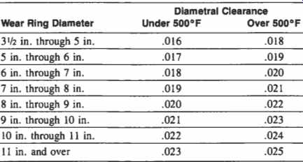
Table 2 Required Diametral Clearances-Process Pumps Wear Rings'
Casing and impeller wear rings are provided at both sides of the impeller on API-type pumps. These rings allow a small clearance to be maintained between the rotating impeller and stationary casing rings. For proper hydraulic performance these clearances should approximate the experience values indicated in Table 2. Rings should be replaced when clearances have increased to a point where hydraulic requirements cannot be met or where inefficient operation would prove wasteful. For API values refer to Table 3.
Why do wear ring clearances deserve our attention? The following section will provide the answer.
Keep Pumps Operating Efficiently
In centrifugal pumps, it is essential to pump operability and hydraulic performance that excessive internal leakage (or recirculation) be prevented. This is accomplished by establishing and maintaining close running clearances been stationary and rotating wear rings which restrict fluid flow to seal between the inlet and outlet of each impeller and between stationary and rotating interstage bushings. These bushings effect sealing between the stages of a multistage pump. Certain types of pumps contain hydraulic thrust balancing devices, another source of internal pump leakage.
As the close clearances become larger through wear, corrosion, erosion or perhaps questionable maintenance practices, internal leakage rates increase. The increased leakage must be pumped and re-pumped continuously by the impeller, requiring additional input horsepower.
The amount of added power to continuously recirculate excessive internal leakage is a function of the pump specific speed*. In low specific speed pumps (low capacity-high head) excessive running clearances result in larger percentage changes in power requirements than occur in high specific speed pumps (high capacity-low head). This is reflected in the empirical data plotted in FIG. 11.

FIG. 11. Added power resulting from excessive wear ring clearance for
different specific speeds.
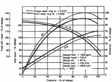
FIG. 12. Pump performance curves.
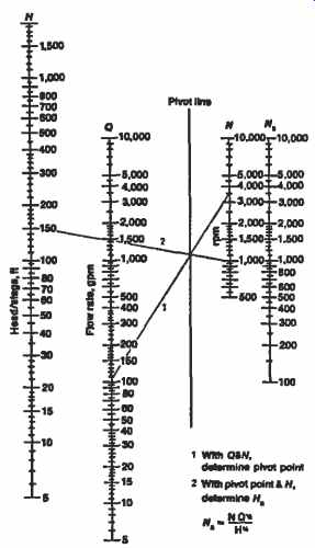
FIG. 13. Specific speed nomogram.
The data in FIG. 11 are somewhat misleading since it may be easy to conclude that high specific speed pumps do not cause excessive costs resulting from worn clearances. Beware, however, that small percentage changes of large horsepowers result in large annual costs. Also, as noted in the following example, mechanical operation may be adversely affected by excessive clearances in pumps of various specific speed ranges.
A typical example: Consider a single stage, overhung process pump-one designed to produce a total head of 725 ft at 1,550 gpm when operating at 3,550 rpm. Such a unit can be considered a typical process pump. FIG. 12 shows the characteristic performance curves for an example pump; all scales are shown as a percentage of the design conditions. The solid curves indicate performance of the pump in new condition.
* Brake horsepower
At the design operating capacity, the unit is 67 percent efficient, requiring 424 bhp* input horsepower (assuming the pumpage has a specific gravity of 1.0). Referring to the specific speed nomogram (FIG. 13), it is determined that our example pump has a specific speed of 1,000. Now, going back to FIG. 11, we see that if the wear rings have worn to the point where running clearances have doubled (increased by 100 percent), a pump having a specific speed of 1,000 will suffer an increase in required horsepower input of approximately 4.8 percent; in our example, this amounts to approximately 20 brake horsepower. The .038 in. wear performance curve on FIG. 12 shows the worn-condition performance characteristics of the example pump.
FIG. 14 shows the annual power cost this extra 20 brake horsepower will represent to you, based on 300 days per year operation.
If your power cost is 6C/kWh, your annual power cost resulting from internal wear in this pump would be $6,440. If yours is a “typical" 100,000 bbl/day refinery using 25,000 pump horsepower, an overall increase of 5 percent in your pump horsepower requirements could represent additional costs of 400,000 per year.
Maintenance practices. Normal operational wear is not the only cause of excessive part clearances in pumps, nor are wasted dollars and fuel the only adverse effects.
Intentional opening up of wear ring or other wearing part clearances is used by some maintenance people to solve certain pump operating problems. Unfortunately, such practices sometimes appear to be effective over the short run. Over a period of time, however, such practices can create other problems. The resulting increased internal leakages within the pump (and the accompanying increased power required to pump the additional flow) seem to many to be a small price to pay, if in fact such criteria are considered at all. But, from a purely mechanical standpoint, the stability of the rotor is perhaps safeguarded only as long as normal running clearances are maintained. Typical consequences of liberally open clearances are likely to include excessive vibration, overheating and ultimately pump or driver bearing failure, shaft breakage, driver overloading, and possible total pump destruction. Ultimate maintenance costs can be very high and unit operation can be compromised through premature and repeated outages.
If two or more pumps are designed for parallel operation and share total capacity, then unequal running clearances can cause unequal load sharing by the pumps. One or more of the units can be forced to operate at significantly more or less than its design flow rate. Efficiency falls off and brake horsepower requirements increase even beyond those caused by excessive running clearances.
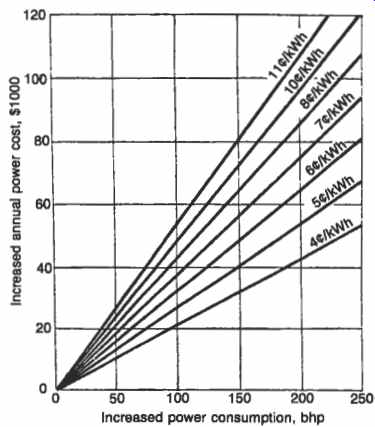
FIG. 14. Annual costs based on 300 days per year continuous operation.
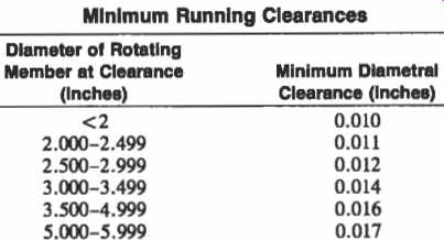
Table 3 Minimum Running Clearances
Running clearances. Greater than normal wear ring clearances at the impeller inlet eye increase the flow rate through the impeller (not out the discharge nozzle of the pump) , increase the effective inlet fluid temperature in the impeller eye, and can introduce undesirable flow patterns in the impeller inlet. On pump installations having marginal NPSH* available, these effects can result in noise, vibration and physical damage normally associated with cavitation.
Original design wear ring clearances can be obtained from the pump manufacturer, and usually agree with the diametral clearances specified by API Standard 610, Section 19. The API recommended clearances are shown in Table 3 and are comparable to the experience values shown in Table 2.
The proper running clearances have been established based on operating economy consistent with good pump reliability.
Over a period of time, the design clearances will change due to wear, corrosion or perhaps as a result of operational problems such as overheating, thermal shock or problems with bearings or shaft sealing systems.
The best way to maintain minimum operating and maintenance costs resulting from increased wear part clearances is to establish a standard practice of measuring the running clearances whenever a pump is disassembled for any reason. On certain multistage pumps having thrust balancing devices, monitoring external balance leak-off flow can be used as a means of gauging wear of internal parts. Increased balancing flows are a direct indication of wear. In addition to measuring running clearances during normal downtimes, wear parts should be checked for eccentricity, out of roundness, and signs of excessive corrosion or erosion.
For best operation, obtain needed replacement parts from a reputable source. This will ensure correct materials, proper heat treatment to maintain correct hardness and wear properties, and proper manufacturing tolerances. It is especially important that special types of wear rings be obtained from a knowledgeable producer; typical special parts include serrated, stepped, or reverse-threaded wear rings, bushings, and thrust balancing devices.
It is always incumbent on process plant management, purchasing, operators and maintenance people to make a conscious effort to minimize operating costs. One very effective way to accomplish this goal is to be alert to the adverse effects of excessive wear part clearances in your pumps.
Calculating the Cost of bur Excess Clearances
Use Figures 11, 13, and 14 to calculate cost of excess wear ring clearances for the pumps in your plant. Since horsepower losses from excessive wear ring clearances vary widely by pump type and index, specific speed (Ns) can be used to simplify these calculations. Use FIG. 13 and the instructions in step 1 to determine the specific speed for your pumps.
Step 1--the nomogram, FIG. 13, solves the Ns equation:
Ns = NQ^1/2/H^3/4
Where:
Ns = pump specific speed,
N = pump speed in rpm,
Q = pump capacity in gpm,
H = total head per stage in ft.
To determine Ns from this nomogram, draw a line connecting Q and N for your pump. Note the intersection of this line with the pivot line. Then draw a line connecting this pivot point (the pivot line intersection of the QN-line) and H; extend the line to the Ns scale and read Ns for the pump.
Step 2-Use FIG. 11 to determine the percent increase in pump bhp for the percentage increase in wear ring clearance and N of your Pump-
Step 3-Determine the normal power requirement of your pump from the manufacturer's performance curve, or calculate the design horsepower as follows:
bhp = (QH13960e) (s.g.)
Where: e = pump efficiency,
Q & H = as defined above.
Multiplying the normal pump power requirement by the percentage determined in step 2 will yield the estimated wasted bhp resulting from excessive wear ring clearance.
Step 4-FIG. 14 can now be used to estimate the increased annual cost in your plant based on your location's cost of electricity.
s.g. = specific gravity of the pumpage,
Pump Assembly Procedures
Horizontal Process Pump Disassembly (FIG. 15)
Dismantling Rotating Element. The back pull-out design of the pump shown in FIG. 15 allows the complete rotating assembly to be removed without disturbing the suction and discharge piping or the driver.
Disconnect all auxiliary piping and drain the oil from the bearing housing. After disconnecting the spacer type coupling (see separate instructions), remove casing stud nuts. Screw bolts into the tapped holes in the casing cover (02) and tighten these jack bolts evenly to facilitate removal of the rotating assembly. The complete rotating assembly can now be moved to a clean area for further dismantling.
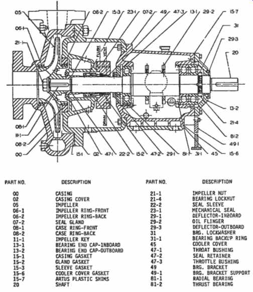
FIG. 15. Crass section and parts list of a horizontal overhung, single
stage process pump.
Dismantling Casing Cover with Mechanical Seal
After the complete rotating element has been taken to a clean work area, the unit can be fully dismantled by following these instructions and referring frequently to the sectional drawing:
1. Remove impeller nut (21-1) {L.H. Threads}.
2. With a suitable puller, remove impeller (05).
3. Remove impeller key (11-1).
4. Unbolt seal gland (07-2) from casing cover and slide back against deflector.
5. Unscrew cap screws holding bearing housing (49) to casing cover (02).
6. Pull bearing housing (49) from casing cover (02). Be careful not to damage the mechanical seal.
7. Loosen set screws holding seal rotating member to sleeve.
8. Pull seal sleeve (22-2) and the mechanical seal rotating element off shaft.
9. Remove mechanical seal from seal sleeve. Note: Mechanical seals have lapped sealing faces. Handle with care, keep wrapped in clean cloth and avoid contacting seal faces.
10. Remove sleeve gasket (15-3).
11. Slide seal gland (07-2) from shaft (20).
12. Pull stationary mechanical seal from gland.
13. Remove gland gasket (15-2) and mechanical seal O-ring.
14. Press throttle bushing (47-3) from gland.
15. Grind off weld between cover (02) and case ring (08-2), and remove case wear ring (08-2).
16. Press throat bushing (47-1) from cover (02).
17. Follow separate instructions for dismantling bearing housing.
Dismantling Bearing Housing
After dismantling the casing cover, the bearing housing can be dismantled (FIG. 15).
1. Remove pump half coupling.
2. Remove deflectors (291 and 29-3).
3. Remove outboard end cap (13-2).
4. Slide shaft assembly out of bearing housing.
5. Remove ball bearing locknut and lockwasher (21-4 and 31).
6. Remove thrust bearing (81-2) and radial bearing (81-1).
7. Remove oil flinger (29-2).
8. "Tap-out" inboard bearing end cap (13-1).
Dismantling of Between Bearings Process Pump
General: The process pump shown in FIG. 16* allows for complete change-out of bearings and mechanical seals without the necessity of disassembling the impeller or casing. To provide clear understanding, the disassembly and reassembly procedures have been broken down into specific sections:
Bearing housings-ball bearing construction
Bearing housings-sleeve bearing construction
Stuffing boxes with various sealing arrangements
Complete disassembly of pump rotating element
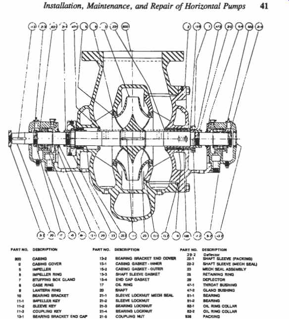
FIG. 16
After the pump has been shut down and the motor secured in the off position, drain pump casing of all liquid. Drain oil from bearing housing and disconnect water and flush piping where necessary.
Note that these procedures are typical and may have to be modified to suit different pump models.
[...]
5. Slide deflector and end cap against sleeve nut.
6. Lift oil ring over oil ring collar to clear housing.
7. Slide bearing housing off bearings.
8. Remove in sequence the following parts: Oil ring (17)
- Bearing lock nut (2 1-4)
- Bearing lock washer (31)
- Oil ring collar (82-2)
Ball bearing (81-1)
Oil ring (17)
Oil ring collar (82-2)
Note: Both inboard and outboard bearing housing and components are identical, with the exception of:
a. Inner oil ring collar at outboard bearing is machined to special width for each pump to obtain correct setting of shaft in relation to stuffing box face.
b. The outboard bearing housing utilizes a bearing spacer (25) to allow the thrust bearing to position the rotating element.
9. Slide end cap (13-1) and deflector from shaft. After inspection has been carried out to verify component integrity, reassembly can be made as follows:
a. Slide deflectors (29) on shaft against sleeve lock nut.
b. Slide end cap (13-1) over shaft against deflectors.
c. Install in sequence these parts: Oil ring collars (82-2) (special at thrust bearing)
Oil ring (17)
Oil ring collar (82-2)
Bearing lock washer (31)
Bearing lock nut (214)
Oil ring (17)
d. Place 1/16 in. thick gasket (154) over inboard end cap and push inboard bearing housing over bearing (watch oil rings); insert dowels and bolt into place.
e. Bring inboard end cap forward and tighten cap screws.
f. Without placing end cap gaskets, slide outboard housing over bearing, bring end cap forward and tighten cap screws between end cap and housing finger tight.
g. Measure gap between housing and end cap and remove bearing housing from bearings.
h. Insert gaskets with a thickness of .003 in. greater than measured gap and push bearing housing over bearings, insert dowels and bolt into place.
i. Bring outboard end cap forward and tighten cap screws.
j. Check shaft assembly for end play. End play should be .002 in.
k. Slide deflectors into place and lock to shaft with socket head set screws.
l. Rotate shaft to check that it is free to rotate and does not bind.
m. Reinstall coupling. Make sure coupling is firmly seated on shaft, and coupling key does not interfere with proper mount ing.
n. Fill housing with proper grade of oil.
o. Check alignment of unit and lubricate coupling (lubricated type only).
Bearing Housing--Sleeve Bearing Construction
This arrangement consists of ring-oiled sleeve-type babbitt-lined radial bearings combined with an angular contact ball thrust bearing. The thrust bearing is relieved in the bore of the housing to assure freedom from interference with the radial alignment, and is oil-ring lubricated. Only portions of FIG. 16 apply.
1. Remove coupling spacer and coupling nut (21-5).
2. Tap pump half coupling off its taper seat on shaft.
3. Loosen socket head set screws in deflectors and slide deflector back against sleeve seat.
4. Remove top halves of bearing housings and sleeve bearings.
5. Remove in sequence:
a. End cap (13-1)
b. Oil ring (17)
c. Thrust bearing lock nut (21-4)
d. Thrust bearing lock washer
e. Oil ring collar (82-2)
f. Thrust bearing and bearing mounting sleeve
g. Thrust bearing spacer
6. Remove lower halves of sleeve bearing and unbolt bearing housings.
7. Slide deflectors off shaft.
After inspections have been carried out and proper clearances verified, these data should be logged for future reference. When all parts are cleaned and corrected as necessary, reassembly can be made as follows:
1. Slide deflectors (29) on shaft against sleeve lock nut.
2. Bring bearing housing lower halves up, install dowels and bolt
3. Place oil rings over shaft into correct housing pocket.
4. Oil shaft and sleeve bearings and "roll" lower half bearings into housing.
5. Push thrust bearing spacer onto shaft. Note: This spacer is machined to special width for each pump to obtain correct setting of shaft in relation to stuffing box face.
6. Assemble thrust bearings into bearing mounting sleeve and install as a unit on shaft (duplex bearings are mounted "back-to-back").
7. Assemble in sequence the following parts: into place.
a. Oil ring collar
b. Bearing lock washer
c. Bearing lock nut (214)
d. Oil ring (17)
e. Top half of sleeve bearings
f. Top half of bearing housings
8. Without gaskets, push thrust bearing end cap into position and tighten cap screws between housing and cap finger tight.
9. Measure gap between housing and end cap and remove bearing end cap.
10. Place gaskets with a thickness of .003 in. greater than the measured gap over end cap and install cap. Draw cap screw down tight.
11. Check shaft assembly for end play. End play should be .001 in. to .003 in.
12. Slide deflectors into place and lock to shaft with socket head set screws.
13. Rotate shaft and check that it is free to rotate and does not bind.
14. Reinstall coupling. Make sure coupling is firmly seated on shaft and coupling does not interfere with proper mounting.
15. Fill housing with proper grade of oil.
16. Check alignment of unit and lubricate coupling (lubricated type only).
Stuffing Box With Mechanical Seal
Most pump stuffing boxes are designed to accommodate different types and makes of mechanical seals. The modified cartridge design allows easy installation and additionally provides protection against sleeve movement on high suction pressure application (Figures 1-15 and 1-16). After the bearings have been disassembled, the mechanical seals can be removed as follows:
1. Unbolt seal gland and slide off shaft.
2. Loosen socket head set screws in sleeve seat and remove nut with spanner wrench.
3. A 10-24 tapped hole is provided in key to assist in removing sleeve key.
4. Pull sleeve and mechanical seal rotating assembly off shaft.
5. Remove mechanical seal from seal sleeve. Mechanical seals have lapped faces-handle with care; keep wrapped in clean cloth and avoid contacting seal faces.
6. Remove sleeve gasket (15-3).
7. Pull stationary mechanical seal from gland (07).
8. Remove gland gasket and mechanical seal O-ring.
9. Press throttle bushing from seal gland.
After inspection has been carried out and all parts are cleaned and corrected as necessary, the mechanical seal can be reinstalled.
1. Press throttle bushing into seal gland.
2. Insert stationary seal face into gland, being careful not to damage O-ring.
3. Slide sleeve gasket against shaft shoulder.
4. Install rotating assembly of mechanical seal on shaft sleeve.
For special seals follow instructions given separately; for standard seals use the following procedure:
a. Wipe both lapped sealing faces with a clean, soft cloth.
b. Apply some oil to sleeve and slide rotating member onto sleeve. Be careful not to put oil on lapped seal faces.
c. Position rotating member on sleeve as indicated on detailed seal drawing to be supplied by seal manufacturer.
d. Tighten set screws which hold rotating member to sleeve.
5. Oil pump shaft and slide sleeve and sleeve assembly against shaft shoulder.
6. Insert sleeve key, tighten sleeve nut with spanner wrench and lock sleeve nut in place with socket head set screw.
7. Bolt seal gland into place.
8. Reassemble bearing housing.
9. Verify that shaft is free to rotate and does not bind.
10. Follow detailed start-up instructions.
Casing Disassembly
The pump shown in FIG. 16 is built in two basic casing arrangements: *
1. Top Suction: Top discharge, centerline supported for hot applications.
2. Side Suction: Side discharge, foot mounted for general applications.
Both arrangements incorporate heavy supports to carry pipe strain and protect the casing from distortion. To reduce the radial load on the impeller and to obtain added strength, all sizes have double volute casings.
Confined spiral-wound gaskets are provided between casing and casing cover. These gaskets not only ensure positive sealing to the atmosphere, but also positively seal the discharge from the suction passages to eliminate casing wash-out at this point. Metal-to-metal contact between casing and cover assures positive alignment and eliminates the need for feeler gauges or other checking devices.
If it becomes necessary to disassemble the complete rotating element, the following procedure can be followed:
1. Dismantle inboard bearing housing
2. Dismantle inboard stuffing box
3. Unbolt casing cover and with help from jack bolts remove remaining rotating assembly.
Note: This assembly is very heavy and mechanical lifting devices are necessary. The eye bolt is not at the center of gravity and care must be exercised to balance the total unbalanced weight.
4. While taking the assembly to a different work area, support the coupling end of the shaft at all times.
5. Clamp the cover flange in a vise and again support the free end of the shaft.
6. Disconnect the thrust bearing housing and the stuffing box.
7. Slide shaft and impeller assembly from casing cover.
8. Remove impeller retaining rings and press impeller from shaft.
9. Case wear rings, throat bushings and impeller wear rings are tack-welded in place. Grind tack-weld off and remove rings and bushings.
After inspection of parts has been carried out and relevant dimensions recorded for future reference, reassembly can be carried out following these procedures:
1. Press case wear rings, throat bushings and impeller wear rings into place and tack weld in three places.
2. Install one impeller retaining ring and impeller key, and press impeller on shaft against ring.
3. Install second impeller retaining ring.
4. Return all parts to casing and with coupling end first place shaft and impeller assembly into casing.
5. Install gaskets, inner gasket into case and outer gasket on cover, and hold in place with heavy grease.
6. Slide casing cover over shaft (watch bearing surfaces and threads) and bolt into place.
7. Reassemble stuffing box.
8. Reassemble bearing housing.
Re-assembling Casing Cover with Mechanical Seal
After inspection has been carried out as outlined in the inspection section, and all parts are cleaned and corrected as necessary, the casing cover can be reassembled by following the instructions given below and by frequently referring to the appropriate sectional drawing, FIG. 15 or FIG. 16.
1. Press throat bushing (47-1) into casing cover (02).
2. Press case ring (08-2) into casing cover (02) and tack weld in three places.
3. Press throttle bushing (47-3) into seal gland.
4. Insert stationary seal face into seal gland (07-1), being careful not to damage O-ring or seal face.
5. Slide gland over shaft against deflector and place sleeve gasket (15-3) on shaft.
6. Install rotating assembly of mechanical seal on shaft sleeve. For special seals follow instructions given separately; for standard seals use the following procedure:
a. Wipe the lapped sealing faces of rotating and stationary elements perfectly clean with a soft cloth.
b. Oil rotating member lightly and slide on sleeve, taking care not to get oil on the seal faces.
c. Position rotating member on sleeve as indicated on detailed seal drawing.
d. Lightly tighten set screws which hold rotating member to sleeve. (see Tables 4 and 5).
7. Oil pump shaft and slide sleeve and seal assembly over shaft.
8. Insert impeller key (11-1).
9. Press sleeve against shaft shoulder and firmly tighten set screw holding seal rotating member.
10. Insert gasket (15-2) into groove on cover (02).
11. Slide casing cover (02) over pump shaft (20) and seal, insert and tighten cap screws between housing (49) and cover. Check location of seal flush connection.
12. Bring seal gland forward and start gland nuts.
13. Squirt a few drops of light oil into the flush connection.
14. Check shaft and make sure it is free to rotate.
15. Draw gland nuts up evenly until metal to metal contact is realized between gland and cover.
16. Push impeller onto shaft and draw up impeller nut (21-1) (L.H. Threads).
17. Return complete back pull-out assembly to pump.
18. Slide casing gasket (15-1) over cover.
19. Slide rotating element into casing and tighten casing stud nuts evenly.
20. Check shaft that it is free to rotate and does not bind.
21. Follow start-up instructions.
Reassembling Bearing Housing
After inspection has been carried out and all parts are cleaned and corrected as necessary, the bearing housing can be reassembled by following these instructions and by frequently referring to the sectional drawing in FIG. 15:
1. Press inboard bearing end cap (13-1) into bearing housing (49) until face is flush with housing. Oil return hole must be properly located.
2. Assemble oil flinger (29-2) on shaft (20) against the shoulder and lock in place with two socket head set screws.
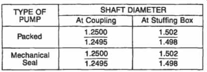
Table 4 Pump shaft diameters
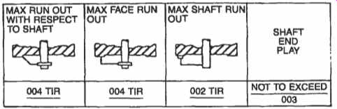
Table 5 Permissible shaft run-out per ft. of diameter
3. Slide thrust bearing (81-2) on shaft (20) as far as possible by hand.
Oil bearing seat on shaft. Place pipe or sleeve over shaft, being sure it rests against inner race only. Tap sleeve evenly until bearing is seated firmly against shaft shoulder.
4. Assemble thrust bearing lock washer (31) and lock nut (21-4).
5. Slide radial bearing (8 11) on shaft (20) as far as possible by hand.
Oil bearing seat on shaft. Place pipe or sleeve over shaft, being sure it rests against inner race only. Tap sleeve evenly until bearing is firmly seated against shaft shoulder.
6. Install shaft (20) and bearing subassembly into bearing housing.
Due to bearing and housing tolerances, it may be necessary to lightly tap shaft until the thrust bearing is seated against bearing housing.
7. Install bearing end cap O-ring or gaskets.
8. Assemble outboard bearing end cap (13-2).
9. Assemble inboard (29-1) and outboard (29-2) deflectors on shaft.
10. Install pump half coupling.
How and Why Centrifugal Pumps Continue to Fail
It is not within the scope of this text to discuss and analyze the obvious differences in operating philosophies, priorities, workforce training, attitudes, etc., that must exist in order to have ten failures at location "A" for every single failure at location "B". Instead, this Section outlines and explains a range of tangible problems and failure causes a competent troubleshooter must pursue and rectify if his or her plant is to become one of the above-average performers. Some of these troubles are perhaps well known but tend to be de-emphasized; others are truly elusive and, therefore, merit close attention.
Selection-related Problems
Centrifugal pump impellers will usually perform well over a wide range of flows and pressures. However, impellers designed for conditions of low NPSHR, Net Positive Suction Head Required, at the suction eye vane tips may suffer from recirculation when operating at low-flow conditions. Recirculation can occur at both the impeller inlet and outlet, and at very low capacities will usually be present at both. Operation at lower than design flows means operation at reduced efficiency: A higher proportion of the power input will be converted to frictional heat.
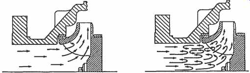
FIG. 17. A section through a single-suction impeller with fluid recirculation
vortices occurring near the periphery.
FIG. 17 illustrates a section through a single-suction impeller with fluid recirculation vortices occurring near the periphery. This internal recirculation will often cause significant reductions in seal and bearing life.
Moreover, operation at low flow will result in higher bearing loads, increased shaft deflection, and potential fatigue failure of pump shafts.'
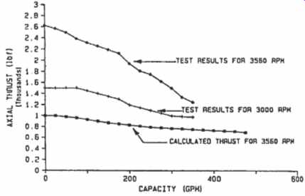
FIG. 18. Lack of hydraulic balance may overload thrust bearings.
Design-related Problems
Although statistically less prevalent, design problems do occur and may have to be addressed. Lack of hydraulic balance may overload thrust bearings (refer to FIG. 18)? Here, the pump manufacturer had calculated a load of 1,000 lbs. at zero-flow conditions. Frequent bearing failures were explained when field tests showed actual loads in the vicinity of 2,600 lbs.
Because ball bearing life changes as the third power of the load ratio, this 2.6-fold load increase would reduce the probable bearing life to 1/17 of the pump manufacturer's anticipated bearing life. The problem was solved by redesigning the pump impeller.
Older pumps that were originally designed for packing as a means to contain the pumpage may be prone to frequent mechanical seal failure. The root cause of the problem may well be related to shaft slenderness; that is, the old braided packing acted as a stabilizing bushing. Insertion of a suitably dimensioned graphite bushing often proved to be beneficial.
There may also be pumps with less than optimum internal gap or clearance values..". Incorrect internal dimensions may cause pump component breakage, involving impellers, fasteners: bearings, or mechanical seals. Correct gap values are given in Table 6.
Installation Problems
A surprisingly large number of installation-related deficiencies continue to plague literally thousands of centrifugal pump users worldwide.
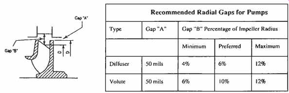
Table 6 Recommended Radial Gaps for Pumps
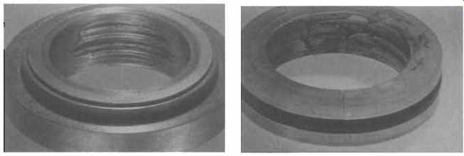
FIG. 19. Piping-induced stresses are prone to create internal misalignment
sufficient to cause the destruction of even the best mechanical seals. (A)
Seal rotating ring. (B) Seal seat.
The importance of not allowing pump piping to exert undue stresses on nozzles and baseplates is simply not appreciated by many maintenance workers, reliability professionals, and operators. When it is not possible for a worker to manually push pump suction or discharge piping into position to mate with the pump flanges, pipe stress is excessive and should be corrected before inserting and torquing up the flange bolting. Regardless of flange and nozzle size, it is never good practice to pull piping into place by means of chain falls or other mechanical stressing devices. Figures 1-19A and B clearly show how piping induced stresses are prone to create pump-internal misalignment sufficient to cause the destruction of even the best mechanical seals.6 Along the same lines, the customary practice of installing an entire pump-and-driver set on a common baseplate and then attempting to level and grout the entire assembly on the concrete foundation is not "best practice." A reliability-minded engineer will insist on installing equipment baseplates by themselves. This will greatly improve the probability of achieving truly level installations. A desirable side benefit will be improved grouting access and full grout support under the entire baseplate. FIG. 20 depicts grouting in progress.
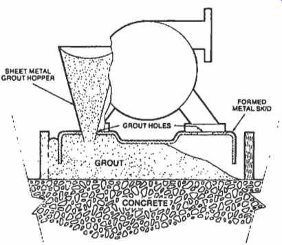
FIG. 20, Pump baseplate grouting in progress.
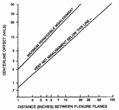
FIG. 21. The lower diagonal line represents reasonable and readily achievable
alignment precision for centrifugal pumps.
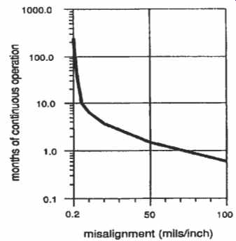
FIG. 22. Estimated time to failure of rotating machinery due to misalignment.
Finally, the detrimental effects of marginal alignment accuracy between driving and driven shafts should prompt pump owners to insist on good alignment. The lower diagonal line in FIG. 21 represents reasonable and readily achievable alignment precision for centrifugal pumps? while FIG. 22 shows the estimated time to failure of rotating machinery due to misalignment?
Assembly-related Problems
A surprisingly large number of pump bearings are assembled without much attention to acceptable fits and tolerances. Table 7 shows bearing bore and shaft diameter minimum and maximum values recommended for centrifugal pump radial bearings. What is perhaps less well known is the fact that mating shafts and radial bearings, which are at the high and low ends of their allowable tolerances respectively, are likely to cause high operating temperatures.
More specifically, oil-ring-lubricated bearings will usually receive enough oil for adequate lubrication, but rarely will this amount be sufficient to preclude hot bearing housings if interference fits are at the high end of the apparent allowable interference spectrum. Hot bearing housings invite operators to pour liberal amounts of water on the assembly; this causes the bearing outer ring to contract and bearing internal clearances to vanish, with rapid failures inevitable. But even if the operator resists the impulse to provide this detrimental means to supplemental cooling, increased oil temperatures will lead to accelerated oxidation of the lubricant.
Angular contact bearings require even more care. Mounted back-to-back and often provided with a small axial preload gap, these bearings are often intended for shaft interference fits in the order of 0.0001 in. to 0.0005 in. only. Sets of these bearings, FAG 73 14B UOI are frequently supplied in centrifugal pumps complying with API 610. FIG. 23 shows that installing two of these bearings back-to-back with a radial interference of 0.0003 in. will produce an almost insignificant preload of approximately 22 lbs.; whereas, an interference fit of 0.0007 in. would result in a mounted preload of 200 lbs.
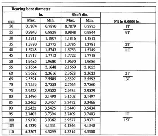
Table 7 Bearing Bore and Shaft Diameter Minimum and Maximum Values Recommended
for Centrifugal Pump Radial Bearings
A much more significant preload would be created by bearing inner ring temperatures higher than bearing outer ring temperatures. With these temperature differences in centrifugal pumps and electric motors typically approaching 50 F, actual preload values could easily exceed 2,000 lbs.
Worse yet, if the operator should decide to "cool" the bearing housing, a 100°F temperature difference might result. At this time, the preload value will increase exponentially and the bearing would be in danger of imminent destruction.
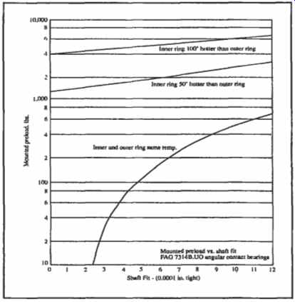
FIG. 23. Shaft fit vs. mounted preload on centrifugal pump bearings.
Improving Seal Life
Several Scandinavian pulp and paper plants routinely achieve in excess of 42 months mean-time-between-failure (MTBF). In 1993, several North American paper mills reported a dismal four months MTBF for their hundreds of mechanical seals. While the failure ratios between North America and Scandinavia are less severely biased in such industries as hydrocarbon processing, there are still untold improvement options available to engineers and technicians who refuse to see their jobs as "'business as usual." A single X in. diameter hole drilled as shown in FIG. 24, will safeguard and dramatically extend the life of many mechanica1 seals by venting air trapped during shop work or gases that might accumulate in stand-by pumps. Of course, operator diligence and conscientious venting of centrifugal pump seal housings could accomplish the same thing.
Another highly beneficial seal life extension program starts by identifying pumpage that contacts seal faces under pressure/temperature conditions at least 15°F away from the initial boiling point (IBP). Many of these applications, and especially those containing massive amounts of solids, are candidates for dead-ended stationary seals and steep-tapered housing bores.
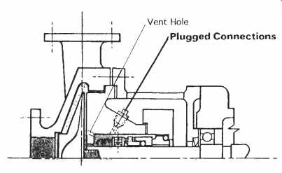
FIG. 24. A single % in. hole will safeguard the life of mechanical seals.
Stationary seals can accommodate greater shaft deflections and higher peripheral speeds than conventional mechanical seals. Many of the most dependable and reliable high MTBF installations use stationary seals in steep-tapered seal housings.
Lubrication: Common But Misunderstood
A rather large number of factors influence lubricating oil degradation and, consequently, pump bearing life. If your centrifugal pumps are equipped with rolling element bearings, there is little doubt that medium viscosity turbine oils (IS0 Grade 68) will perform better than lighter oils originally specified by many pump manufacturers. However, by far the most frequent cause of lube oil related failures is due to water and dirt contamination. With only 20 ppm water in pure mineral oil, bearing race and rolling element fatigue life is reduced by an incredible 48 percent. Although the fatigue life reduction is less pronounced with inhibited lubricants, there are always compelling reasons to exclude water and dirt from pump bearing housings. Lip seals are a poor choice for centrifugal pumps requiring high reliability. Face seals offer superior "hermetic" sealing and should be given serious consideration. On a related subject, have you explained to your operators and maintenance personnel that a full bottle oiler is no guarantee of adequate lubrication? The height of the beveled tube determines the level of oil in the bearing housing, and all too often there will be costly misunderstandings.
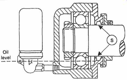
FIG. 25. The sealing film near the bearing end cap.
However, there are at least two considerably more elusive problems involving bottle oilers.
The first is shown in FIG. 25. With a relatively viscous oil and close clearance at the bearing housing end seal-point S-an oil film may exist between seal bore and shaft surface. Good lube oils have a certain film strength and, under certain operating conditions, this sealing film near the bearing end cap may break only if the pressure difference between the bearing housing and atmosphere exceeds % in. of water column.
If the bearing housing is exposed to a temperature increase of a few degrees, the trapped vapors--usually an air-oil mix-floating above the liquid oil level will expand and the pressure may rise to 14 in. of water column.
While this would not be sufficient to rupture the oil film, the pressure buildup is sufficient to depress the oil level from its former location near the center of the bearing ball at the 6 o'clock position, to a new level now barely touching the extreme bottom of the lowermost bearing rolling element. At that time, the bearing will overheat and the lube oil in contact with it will carbonize. An oil analysis will usually determine that the resulting blackening of the oil is due to this high temperature degradation. The second oil-related problem causes the contents of bottle oilers to turn grayish in color. This problem is primarily observed on ring-oil lubricated rolling element bearings.
Suppose you have aligned precisely the shafts of the pump and driver.
Nevertheless, shims placed under the equipment feet in order to achieve this precise alignment caused the shaft system to slant 0.005 in. or 0.010 in. per foot of shaft length. As a consequence, the brass or bronze oil slinger ring shown in FIG. 26 will exhibit a strong tendency to run "downhill."
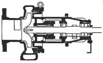
FIG. 26. Centrifugal pump with oil slinger ring.
Bumping into other pump components thousands of times per day, the slinger ring gradually degrades and sheds numerous tiny specks of alloy material. The specks of metal cause progressive oil deterioration, and ultimately, bearing distress.
Pump users may wish to pursue one of two time-tested preventive measures. First, use properly vented bearing housings or, better yet, hermetically sealed bearing housings without oiler bottles. The latter are offered by some pump manufacturers and incorporate bull's-eye-type sight glasses to ascertain proper oil levels. The second preventive measure would take into account the need for radically improved pump and driver leveling during shaft alignment or, even more desirable, apply flinger spools as shown in FIG. 27. Oil mist lubrication or direct oil injection into the bearings would represent a more dependable, long-term oil application method for centrifugal pumps.
Other Practices Responsible for Reduced Pump Reliability
Among the most wasteful and costly practices leading to premature distress in pump antifriction bearings is water cooling. When applied to bearing housings, cooling water causes the bearing outer ring to contract. The resulting increase in bearing preload will often reduce the bearing life expectancy.
Similar distress may be introduced by moisture condensation due to cooling of air present in the bearing housing.
Avoidance of cooling water is feasible if ISO Grade 68 or 100 mineral oils are used. Even better results have been obtained in installations using oil mist lubrication or properly compounded synthetic oils of the diester and/or polyalphaolefin type. Many refineries have stopped using cooling water in pump applications with fluid temperatures around 740°F. Similarly, a large number of pump users have come to realize that water-cooled pump support pedestals represent a serious liability at worst, and an unnecessary operating expense at best. Unforeseen corrosion incidents have led to the collapse of pedestals, in turn causing disastrous pump fires. Alignment of driver and driven shafts with predetermined offset values have proven satisfactory in every case.
Assembly-induced bearing problems also deserve attention. Rolling element bearings furnished with plastic cages can suffer damage when overheated in defective heaters. They will be destroyed when heated by open flames, a practice observed on the assembly floor of a pump manufacturer in the 1980s. Do your maintenance/technical personnel know which code letter identifies plastic cages? The answer is "P," for SKF bearings. Do they know that the letter directly behind the bearing identification number identifies the load angle and that dimensionally interchangeable angular contact bearings using the same number, but differing in just this one letter, may have allowable load ratings that differ by a factor of 8:1? Compelling reasons for developing a purchase specification for your rolling element bearings, and even more compelling reasons for personnel training!
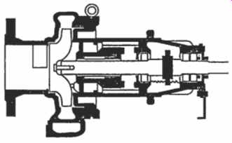
FIG. 27. Centrifugal pump with flinger spool.
PREV. | NEXT | Article Index | HOME