AMAZON multi-meters discounts AMAZON oscilloscope discounts
Part I -- Installation and Repair of Major Process Equipment
Section 1 -- Installation, Maintenance, and Repair of Horizontal Pumps
The most common centrifugal pump in the petrochemical industry is the horizontal single stage process pump. This pump has many different external designs. Perhaps the most common is the end suction top discharge design shown in FIG. 1.
There are many features about this pump that make it adaptable for most applications. Designs can be small and inexpensive, or they can be designs that meet API 601* standards as well as with ANSI** specifications. The top centerline discharge provides excellent stability when subjected to piping stresses and high temperatures. Larger pump models incorporate a double volute internal passageway that helps to balance radial loading on the impeller. This pump design has a vertical radial split casing with centerline supports and an overhung impeller mounted on a shaft supported by bearings. By changing impeller designs, this pump can be adapted to all kinds of product applications from light hydrocarbons to slurries.
ANSI pumps differ from API* designs as follows: They are chemical process pumps designed in accordance with ANSYASME B73.1M-199 1 (horizontal end suction) and ANSYASME B73.2M-1991 (vertical inline). ANSI pumps (FIG. 2) are generally supplied with open impellers.
-------
* API = American Petroleum Institute
** ANSI = American National Standards Institute
-------
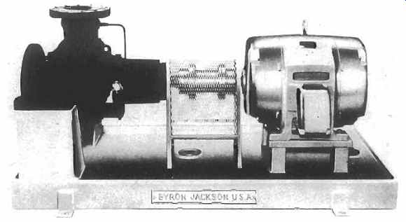
FIG. 1. Horizontal single stage process pump to API (American Petroleum
Institute) Standard.
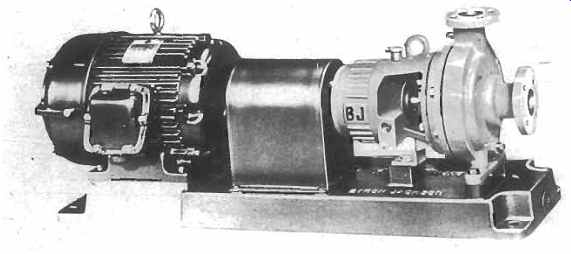
FIG. 2. Typical ANSI horizontal process pump with foot mounted casing.
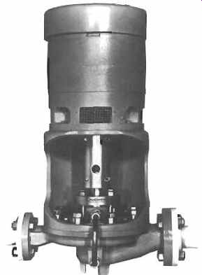
FIG. 3. Vertical inline centrifugal pump. Rigid coupling, impeller, stuffing
box and mechanical seal can be removed without disturbing motor and piping.
Temperatures are usually limited to 300°F and pressures to 300 psi maximum, depending on the material and flange type. Capacity ranges from 0-5,000 gpm, and materials are mostly ductile iron cases and impellers. Often stainless steel is used together with 316 stainless steel shaft sleeves. Pump suction and discharge will normally have 150 lb raised face flanges . Mechanical seals provided in ANSI pumps are normally unbalanced, single inside, but single outside seals are also quite common. Face materials are often carbon versus ceramic or tungsten carbide. Other materials can be substituted where applicable. Seal flush is usually configured as recirculation from pump discharge.
Motors: TEFC (totally enclosed fan cooled) 460 volt (560 in Canada), three phase at 60 Hertz are standard drivers for North American applications.
Base Plates: Normally fabricated from steel plate with smaller base plates cast. Pump and motor are mounted on the base plate and connected with a coupling. For maintenance and repair work the coupling will have to be removed and the pump internals can be removed from the pump case without disturbing the piping.
ANSI vertical in-line pumps are made in three basic designs: Style "A" is identified by the rigid spacer coupling which connects the pump stub shaft to the motor shaft. This design allows pump mechanical seal and impeller to be removed without disturbing the motor or pump flanges.
All radial and thrust loads are transferred to the motor bearings. This style of pump is shown in FIG. 3.
Style "B" consists of a horizontal pump mounted in vertical position with a special in-line casing and motor support. The motor is mounted on top of the support and is connected to the pump with a flexible coupling that allows pull out of pump without disturbing the piping.
The advantage of this pump design is that radial and thrust conditions are controlled by the pump bearings rather than the motor bearings. Also some parts are interchangeable with horizontal models. FIG. 4 shows this style of pump.
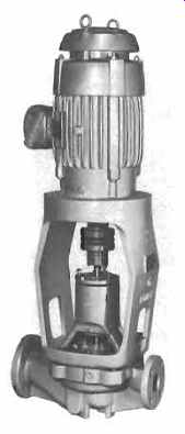
FIG. 4. Vertical inline pump. Pump shaft is supported with its own independent
bearings which also protect against radial thrust and shaft run-out.
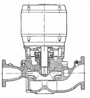
FIG. 5. Vertical inline pump, close coupled design. Impeller and mechanical
seal are mounted on motor shaft.
Style "C" is the close-coupled design. The motor shaft is extended, and the impeller and mechanical seal mounted on it (no separate pump shaft needed). One disadvantage with this is that if anything goes wrong with the seal or pump, it can also cause damage to the motor. This design (see FIG. 5) is being used less and less. API vertical in-line pumps will be discussed later.
APZ (American Petroleum Znsritufe) style pumps are designed for petrochemical services in accordance with API Standard 610. API standards define minimum requirements for pumps in heavy duty hydrocarbon service.
API pumps are generally specified in steel or noncorrosive materials with 300 lb raised face (RF) flanges. The pump casings are available with centerline supports rather than foot supports to reduce alignment distortion at high temperatures. The pressure limitations are at approximately 700 PSI with a maximum temperature of 850°F. API pumps are required to have closed impellers with case and impeller wear rings.
The base plate and motor requirements will be the same as the ANSI pumps, although the procurement of sturdier baseplates is advisable.
Principles of Installation of Pumps and Drivers
The correct installation of pumps and drivers is an often overlooked requirement. Incorrect installation indirectly costs millions of dollars a year in increased maintenance and lost production due to premature equipment failure.
This segment of our text provides a set of guidelines that will result in a good pump installation. While centered around a typical single-stage, overhung, centrifugal pump, and a motor driver, it can easily be adapted to all types of machinery--the principles are the same. And, while these guidelines prescribe the minimum requirements to be performed by the installing agency, any specific instructions provided by the equipment manufacturer should also be observed. Conflicts should be resolved prior to installation.
Preinstallation and Equipment Preservation Measures
When a pump is shipped from the manufacturer to the field, it normally is "suitably prepared" for short duration storage up to approximately six months. It is very important that the integrity of the equipment be maintained during the construction phase of the installation. Many pieces of equipment have been ruined before they had a chance to operate, because of mishandling in the field prior to unit start-up.
A good preinstallation program should accomplish the following:
1. Inspect all equipment upon arrival for any shipping damage.
2. Ensure good lifting practices are followed when transporting all equipment; a pressure gauge makes a vulnerable spot to place a lifting strap while off-loading a pump.
3. All nozzles and openings should be kept covered or plugged until piping is attached. Besides keeping out the elements, this will prevent foreign material such as welding rods, rags, waste paper, etc., from getting in the machine and causing damage. Disassembling a pump during a unit start-up to remove debris can be quite expensive.
4. If more than six months will pass before the equipment is expected to run, consideration should be given to respraying the pump internals with a suitable rust preventive. Better yet, the pump could be preserved by the application of oil mist. Ensure that whatever is used is compatible with any elastomers it may come in contact with, is easily removable, and is applied according to manufacturer's instructions.
5. Fill all oil-lubricated bearings with the proper lube oil as soon as possible. If the bearing is to be oil mist lubricated, consider attaching and using the oil mist generator during the construction phase of the project. If not, fill those bearings with oil also. Greased bearings present a different problem. All greased bearings should be repacked with the correct grease as soon as possible. Follow manufacturer's instructions; however, ensure that all the old grease is displaced by the new grease. Different greases have different additives that normally are not compatible with each other. Mixing two noncompatible greases will reduce the beneficial properties of either grease.
6. Coat all exposed machined surfaces with either a rust preventive or grease to protect them from the environment.
7. In order to prevent corrosion of the shaft sleeve, packed pumps received with the packing installed should have the packing completely removed immediately on arrival and the shaft sleeve and gland greased. Normally, packed pumps are shipped with an extra set of packing. Of course, just before starting, this packaging should be installed in the pump.
8. Likewise, steam turbines received with the carbon rings installed should have the rings removed immediately on arrival and the shaft greased. The rings should then be reinstalled just prior to start-up.
Caution should be taken when removing and installing rings. Axial ring orientation and location as well as the direction of shaft rotation is critical. Be sure to consult the manufacturer's instruction manual for details.
9. Pump mechanical seals are precision components and therefore require special handling during transport and installation. When moving pumps with seals, the pumps should be securely restrained to prevent excessive vibration and/or damage to the shaft and seal by dropping or bumping the shaft. When installing or lifting the pump, do not use the shaft as a leverage or lifting point.
On new installations, if a mechanical seal is to fail, it normally will do so within the first few hours of operation. The primary causes can often be traced to improper installation of the seals, or mishandling of seals during pump installation.
Foundation and Anchor Bolts
The design of equipment foundations and the different characteristics of concrete and grouts are thoroughly discussed in Volume 3 of this series, so we will not go into great detail here. However, there are some general guidelines to follow that will ensure a good installation.
1. Assuming that the forms and steel reinforcing rods are all sized and placed according to approved drawings, the next most important step is the placement of the anchor bolts. Prior to the actual concrete pour the anchor bolts should be:
a. Accurately set according to the foundation drawings and firmly secured to prevent shifting during the pouring process.
b. Dimensionally checked (and rechecked) versus the foundation drawings for proper length, diameter, thread length, etc.
c. Checked for proper projection; i.e., checked for correct elevations as referenced to an established benchmark. It can be very embarrassing to set a baseplate on a new foundation and find that the anchor bolts are not long enough to pass through the baseplate and the hold-down mats.
d. Install metal or plastic anchor bolt sleeves. Remember, sleeves are not intended to encourage careless positioning of the anchor bolts. However, they will allow for slight errors in baseplate hole layouts and small shifting of the anchor bolt during the concrete pouring process.
e. Ensure that the exposed threads are protected by coating with heavy grease or with paste wax. The exposed bolts should be covered with plastic wrap and the wrap firmly secured with wire.
2. After the pour, the surface of the foundation should be chipped to remove all laitance and defective or weak concrete. Normally, a chipping hammer should be used; sand blasting or using a needle gun is not effective. The amount of concrete removed should be such that the final baseplate or soleplate elevation allows for one to two inches of grout between the surface of the foundation and the lower baseplate flange or the underside of the soleplates. After chipping, the top surface should be reasonably level and free of all oil, grease, and loose particles.
3. Baseplates or soleplates should not be placed on the foundation until a minimum of ten days has elapsed after pouring the normal concrete. High early-strength concrete may be used in some specific applications but is not usually required. In any event, baseplates and soleplates should not be placed on foundations until the concrete has had time to dry and cure so that 85 percent of the shrinkage has taken place.
4. Protect the surface of the foundation according to the type of grout to be used. When using epoxy grout, the concrete surface must be dry at the time the grout is applied. When using cement-based grout, keep the foundation wet for the period of time recommended by the grout manufacturer prior to grouting.
5. If used, remove the tops of the plastic anchor bolt sleeves and ensure that the sleeves are free of foreign material.
Baseplate and Soleplate Preparation
1. While the practice varies from company to company, it is suggested that all equipment be removed from its baseplate or soleplate prior to grouting. This aids in leveling the plate and prevents unwanted distortion of the baseplate. The machinery can easily be reinstalled after the baseplate or soleplate has been grouted.
2. Normally, baseplates and soleplates are provided by the equipment supplier and manufactured in accordance with some company or industrial specification. The installing agency must inspect and verify that the baseplate or soleplate is in accordance with these specifications but, as a minimum, it should have the following:
a. All baseplate and soleplate surfaces (except on mounting pads and in threaded holes but including the outside edges) that will be in contact with the grout should be coated with an inorganic zinc silicate or other primer compatible with the grout being used.
Base metal, blistered, or rusted surfaces are unacceptable.
Note: Depending on the type of epoxy grout used, if the primer has been on the baseplate for an extended period, the surface may gloss over and thus prevent bonding. If this occurs, the baseplate must be stripped of all old primer by sand blasting to near white metal and recoated prior to grouting. Check the manufacturer's instructions carefully to determine if this is a potential problem.
b. Ensure all baseplates are provided with at least one grouting opening in each bulkhead section and/or each 12 sq ft of base area as a minimum. Vent holes should be provided at the corners of each bulkhead compartment. These will ensure that the grout will flow from the pour hole to the extremities of each compartment and that no voids are created by trapped air.
c. The corners of all baseplates and soleplates should be rounded to at least a 20-in. radius. As the grout cures, there will always be some shrinkage. Rounding the corners prevents stress concentrations in the grout that would eventually cause cracking.
3. Before setting the baseplate, ensure that all surfaces to be in contact with the grout are free of oil, grease, and rust.
4. Position the baseplate or soleplate on the prepared foundation, supporting it on leveling screws, rectangular leveling shims, or wedges having a small taper. These support pieces should be placed next to each foundation bolt to prevent distortion. Cover all leveling screws with grease or a heavy paste wax to prevent the grout from adhering. If using an epoxy grout, wax, mask off, or grease all areas that require protection from grout splatter.
5. Use a precision level and level the baseplate or soleplate side-to-side, end-to-end, and diagonally to within .002 in. per ft. Remember, it is mandatory that the machined mounting surfaces be flat and parallel. Corresponding mounting surfaces in the same place should be within .002 in. parallel overall. This mounting surface tolerance must be maintained after all anchor bolts have been adequately tightened. This will prevent overstressing and distortion of the equipment and/or base once the machinery is remounted.
6. After leveling, check that all support wedges or shims are in contact with the foundation and plate, then tighten the foundation bolts evenly but not too tight, and recheck level.
7. Check the elevation of the machined mounting surfaces of the baseplate or soleplates. Remember, the proper elevation should allow for a minimum of %in. shim thickness under the equipment. If everything checks out properly, the baseplate is ready for grouting.
Grouting Overview
Epoxy Grout
1. Timing and proper mixing are the keys to successful grouting. The grout supplier's instructions must be followed implicitly. Before mixing the various components, everything else should be ready surfaces cleaned and dry, forms completed and sealed, pushing tools, rags, cleaning solvents available, and adequate manpower allocated.
Note: In general, epoxy grout is flammable, toxic, poisonous, and corrosive. Therefore, material should be kept away from open flame, high heat sources, or sparks. It should be mixed in a well-ventilated area. Workmen should wear eye protection, gloves, and protective clothing at all times during mixing and placing of grout and aggregate.
2. Grout forms should be built of materials of adequate strength and should be securely anchored and shored to withstand the pressure of the grout under working conditions.
Epoxy grout forms must be coated with a paste wax, e.g., colored floor type wax, on areas that will come in contact with the grout to keep them from becoming bonded to the grout. All wax should be removed from the concrete, baseplate, or soleplate before grouting. To permit easy clean-up, wax or cover all surfaces where grout may splash.
Forms should be liquid tight because epoxy grout will flow through even the smallest opening. Any open spaces or cracks in forms or at the joint between forms and the foundation should be sealed off using rags, cotton, foam rubber, caulking compound, etc . Because of epoxy grout's higher compressive and tensile strengths and its readiness to bond to metals, the top of the grout outside the baseplate or soleplate should be brought up along the side of the baseplate or soleplate to give some protection against lateral movement. The top of the grout on baseplates with flange-type support should be at the top of the flange. The top of the grout on baseplates with solid sides and soleplates should be 1 in. above the bottom of the baseplate or the underside of the soleplate. The outside top edge of the grout should be chamfered at 45 deg.
3. Foundation anchor bolt sleeve should be filled with a nonbonding, pliable material such as asphalt or silicone rubber molding compound to prevent a water pocket around the anchor bolt.
4. A split hose or duct tape can be used around the exposed threads of anchor bolts to prevent direct contact between the epoxy grout and anchor bolts.
5. The foundation should be protected from the rain since it is important that the foundation be clean and dry at the time of grouting.
Normal grouting temperature should be between 40° and 90°F. Due to the accelerated rate of curing at high temperature, the shading of the foundation from summer sunlight for at least 24 hours before and 48 hours after grouting may be required. In hot summer weather, it is preferable to place the grout during the after noon, so that the initial cure will occur during the cooler evening hours.
In cold weather, the grouting materials (including the aggregate) should be stored at a temperature above 70°F for 24 hours prior to mixing. When the temperature is below 65°F, the grout manufacturer should be consulted before mixing and placing the grout.
However, for best results in cold weather, fabricate a temporary shelter around the baseplate or soleplate to be grouted and pre-warm the baseplate or soleplate and foundation. When pre-warming the installation, use convection-type space heating equipment and be careful not to overheat localized areas. Do not use radiant heating or open steam. Radiant heating warms the grout upper surface more than the lower surface. The grout surface therefore cures in a thermally expanded state, and after dissipation of the heat, produces stresses that tend to make the grout "curl-up," resulting in cracks in the concrete at the foundation corners just below the grout line.
6. Epoxy grout has a limited shelf life. Check instructions prior to use.
7. Epoxy grout has a limited pot life. Check the grout manufacturer's instructions prior to use.
8. Epoxy grout should have a consistency very similar to that of a hydraulic cement slurry but with self-leveling flow characteristics. Epoxy grouts can generally be handled with the same methods and tools used with flow grade, sand-cement grouts. Epoxy grout can be manually mixed in a wheelbarrow using a mortar mixing hoe or a small cement or mortar mixer. Over-mixing and/ or violent mixing whips air into the grout, and results in a weaker grout.
9. The actual placing of the epoxy grout can be accomplished by several means. Some companies prefer to force the grout into place, while others use their ingenuity and place the grout by various devices. Epoxy grout is very viscous; however, it will flow and seek its own level given time and an ambient temperature above 35°F. Generally, it is best to start placing the grout at one end of the baseplate or soleplate and work toward the other end in such a manner as to force the air out from beneath the baseplate or soleplate to eliminate voids as the grout moves along. A floating trowel is very helpful in forcing grout underneath by simply applying pressure on top. Plywood strips, sheet metal strips, wires, and push rods may also be used to place the grout completely under the baseplate or soleplate, but care should be exercised to prevent working air into the grout.
Note: Check the forms frequently for leaks. Leaks do not self-seal. If not stopped, they will cause voids.
10. Epoxy grout curing rate depends on the temperature and pour thickness. Lower ambient temperatures and very thin layers of grout require longer curing time.
Forms may be removed when the epoxy grout is adequately cured.
This generally occurs in approximately 12 to 24 hours at 75°F or when the surface becomes firm and not tacky to the touch. When an accelerator is used, follow the manufacturer's instructions to determine the typical curing times required.
11. After the grout has cured, the baseplate and soleplate should be checked for complete grouting by tapping the baseplate or soleplate with a steel bar. If grouting voids are found based on a "hollow" sound, holes can be drilled in the baseplate or soleplate deck at each end of the voids and the voids filled with epoxy grout without aggregate; one hole should be used for the grout and the other hole as an air vent. A grease gun is normally used to force the grout into voids. When pressure injection is used, install dial indicators on the baseplate or soleplate deck to confirm that epoxy placement is being accomplished without lifting the baseplate or soleplate deck.
12. The leveling shims or wedges used to level the baseplate or soleplate can be left in place after grouting. If for some reason they are removed after the grout has cured, the resulting voids should be filled with epoxy grout without aggregate.
If leveling screws are used, they should be removed after the grout has cured to allow the full equipment weight to be distributed evenly over the grouted area.
The foundation anchor bolts can now be retightened and the pump and driver installed. The pump and driver are now ready for alignment.
Cement-Based Grout
1. The grout manufacturer's requirements and instructions should be strictly followed.
2. For dry packing of cement-based grout.
3. Grout forms should be built of materials of adequate strength and should be securely anchored and shored to withstand the pressure of grout under working conditions. Forms should be tight against all surfaces, and joints be sealed with tape.
Grout forms must be coated with form oil on areas that will come in contact with the grout to keep them from becoming bonded to the grout. All oil should be removed from the concrete, baseplate, or soleplate before grouting. To permit easy cleanup, cover all surfaces where grout may splash.
4. Prior to placing the grout, the top surface of the concrete foundation should be saturated with water for the time period recommended by the grout manufacturer. Excess surface water and water in the foundation bolt holes should be removed just prior to placing the grout.
5. Foundation anchor bolt sleeves should be filled with a nonbonding, pliable material such as asphalt or silicone rubber molding compound to prevent a water pocket around the anchor bolt.
6. A split hose or duct tape may be placed around the exposed threads of anchor bolts to prevent direct contact between the grout and anchor bolts.
7. The temperature of the baseplate or soleplate, supporting concrete foundation, and the grout should be maintained between 40° and 90°F during grouting and for a minimum of 24 hours thereafter.
8. Grout should be mixed with only water to produce the desired consistency according to the procedures recommended by the manufacturer.
Caution: Check the quality of the water being used; ensure that it is oil free.
9. The placement of the grout should be rapid and continuous so as to avoid cold joints under the baseplate or soleplate. Generally, it is best to start placing the grout at one end of the baseplate or soleplate and work toward the other end to force the air from beneath the baseplate or soleplate to eliminate voids as the grout moves along. A floating trowel is very helpful in forcing grout underneath by simply applying pressure on top. Plywood strips, sheet metal strips, wires, and push rods may also be used to place the grout completely under the baseplate or the soleplate, but care should be exercised in order to prevent working air into the grout.
10. Grout should be cut back to the bottom outer edge of the baseplate or soleplate and tapered to the existing concrete. The top of the grout on baseplates with flange-type support should be at the top of the flange. The top of the grout on baseplates with solid sides and soleplates should be 1 in. above the bottom of the baseplate or the underside of the soleplate. The outside top edges of the grout should be chamfered at 45 degrees.
11. After the grout has reached an initial set (the grout can be cut with a steel trowel and will stand up without support), it should be trimmed back to the level indicated on the drawings.
12. Grout should be cured according to the manufacturer's specifications and recommendations.
13. After the grout has cured, the baseplate or soleplate should be checked for complete grouting by tapping the baseplate or soleplate with a steel bar. If grouting voids are found based on a "hollow" sound, holes should be drilled in the baseplate or soleplate deck at each end of the voids and the voids filled with epoxy grout without aggregate; one hole should be used for the grout and the other hole as an air vent. A grease gun is normally used to force the grout into voids. When pressure injection is used, install dial indicators on the baseplate or soleplate deck to confirm that epoxy placement is being accomplished without lifting the baseplate or soleplate deck.
14. Forms should remain in place for a minimum of 24 hours except where form removal is needed to trim back grout.
15. The leveling shims or wedges used to level the baseplate or soleplate may be left in place after grouting. If for some reason they are removed after the grout has cured, the resulting voids should be filled with grout without aggregate.
If leveling screws are used, they should be removed after the grout has cured to allow the full equipment weight to be distributed evenly over the grouted area. The holes should be caulked with putty.
The foundation anchor bolts can now be retightened and the pump and driver installed. The pump and driver are now ready for alignment.
Machinery Alignment
Section 5, Volume 3 of this series deals extensively with equipment alignment, and it is not our intent to duplicate the efforts of others in this area. However, here are several general steps to follow which will result in a well-aligned, trouble-free machine:
1. The owner should insist that the installing agency use the reverse indicator method of alignment, or the laser alignment method, whenever the separation between shaft ends is larger than 50 percent of the diameter at which the dial indicators contact the coupling rim. The advantages of using this system far outweigh the arguments for rim-and-face and other mechanical alignment methods. If you or your contractor are unfamiliar with reverse indicator alignment, get a book and learn, or purchase one of the small hand-held calculators now available that are based on this system.
2. Measure and adjust the distance between the driver and the pump shaft ends (D. B . S. E .) . This distance should be in accordance with the pump layout drawing and within the tolerance provided by the coupling manufacturer or guideline value of Section 5, Volume 3 of this series. The D.B.S.E. should be set with the pump and driver shafts pulled toward each other for turbine drives and motor drives with antifriction bearings. For motor drives with sleeve bearings, the D.B.S.E. should be set with the motor shaft at its magnetic center.
3. Measure and adjust the distance between the driver and the pump shaft ends (D.B.S.E.). This distance should be in accordance with the pump layout drawing and within the tolerance provided by the coupling manufacturer. The D.B.S.E. should be set with the pump and driver shafts pulled toward each other for turbine drives and motor drives with antifriction bearings. For motor drives with sleeve bearings, the D.B.S.E. should be set with the motor shaft at its magnetic center.
4. Both the driver and pump shafts should be checked for mechanical runout using a dial indicator. Mechanical runout should not exceed .002-in. total indicator reading (TIR).
5. Driver-to-pump and pump-to-driver alignment targets should be provided to the installation contractor before starting the alignment. These targets should include allowances for thermal growth of hot pumps and steam turbines. If the actual cold targets are not provided, the amount of vertical growth due to temperature may be estimated using the following formula:

6. Initial alignment should be made at ambient temperature and "pipe-free"-no
pipe forces or weight on the equipment (pump and turbine flanges should be
unbolted).
7. To eliminate adding mechanical runout to alignment error, indicator readings should be taken by turning the pump and driver shafts together.
8. Tighten the equipment hold-down bolts and recheck the alignment; adjust as necessary.
Check for a "soft foot" by loosening each hold-down bolt in turn while measuring with a dial indicator movement between machine foot and soleplate or baseplate. If movement exceeds approximately .001-in. (.025 millimeters) at any foot, shim changes should be made to eliminate the "soft foot" and alignment rechecked before proceeding.
9. The alignment should be checked and recorded after both bolt-up of all piping to the pump and bolt-up of all piping to the driver. No significant strain should be present as indicated by any change in the pump-driver alignment. A change in alignment of more than 0.001-in. from the pipe-free condition should be investigated and the piping strain corrected. When "cold set" has been included in the piping design, the final alignment must be checked and the tolerances met after the system has reached normal temperature.
10. Pumps operating at over 300°F and all steam turbine drivers should be hot aligned; that is thermally cycled to normal operating temperatures and realigned, if at all possible, while hot. This will ensure that the alignment tolerances are still being met under operating conditions.
11. After the final alignment has been approved, the support pads for the pumps and drivers should be drilled at two locations and tapered dowel pins with threaded ends to facilitate removal should be installed. Unless specifically located by the equipment manufacturer, the dowel pins should be placed near the thrust bearing end of the equipment.
Pre-Operational Checks
The following is a checklist of items that should be looked at before actually starting up the equipment. The list is by no means complete for all types of machinery but should act as a mind jogger before initial startup.
1. For pumps with double mechanical seals or packing with external gland oil, the gland oil supply piping should be cleaned by oil or solvent flushing prior to connecting to the pump. The oil system should be flushed at the design flow rate at a temperature of about 160°F (or lower, as component design dictates) using the system pump and lint-free cloth filter bags at all seal or packing inlet connections; oil should be circulated for a minimum of four hours.
The filter bags should be examined and cleaned at approximately 30 minute intervals. Flushing should be continued until there is no evidence of particle pickup for two consecutive 30 minute periods.
2. For pumps with tandem mechanical seals, the overhead reservoir and all flush oil supply piping should be thoroughly cleaned by oil flush prior to connecting to the pump.
3. It is important for good seal or packing performance that dirt and/ or foreign debris not be introduced into the seal or packing cavity.
Note: Pumps with double mechanical seals should not be flushed out, steamed out, pressure tested, or operated without the seal gland oil system in operation at the specified pressure level. The gland oil system pressure should be 10-15 psi higher than the pump side pressure on the inner seal for all operating conditions.
This will prevent inadvertent blowing open of the seal with pumped product that could cause seal failure or contamination of the flush system.
4. The flushing and steaming of pumps with single or tandem mechanical seals should be held to a minimum period of time. This will minimize the amount of debris entering the seal cavity, and prevent the destruction of the static seal elements by overheating.
Static seal elements should not be heated above the temperatures listed in Section 10 of Volume 3.
5. All cooling water piping on pumps and turbines should be flushed and connected prior to operation.
Prior to operation, any lube oil in bearing housings and constant level oilers should be drained and new, clean lube oil added, and the proper oil level established. Verify that the oil level in the bearing housing is correct and that the constant level oiler is functioning properly. The owner should verify that the installing agency is using the proper grade of lube oil.
6. On equipment to be lubricated by an oil mist system: install all local oil mist piping or tubing with a slope toward the equipment without any sags or low spots in the piping or tubing runs; install transparent sight bottle on bottom of bearing housing. Prior to operating the equipment, verify that oil mist flows to each bearing.
Note: Unless you prelubricate with a high-viscosity lube oil, the oil mist system must have been in operation for a minimum of 12 hours prior to attempting to run any equipment.
7. Motor drivers should be power-rotated to check for proper direction of rotation prior to coupling to the driven equipment.
8. Turbine overspeed trip setting and governor operation must be checked prim to coupling to the driven equipment.
9. Gear type couplings should be packed with the proper grease and the pump and driver coupled up. Recheck the coupling float and verify that it is within the coupling manufacturer's tolerances.
10. The coupling guard should be installed prior to rotating any shaft under power.
11. If a separate lube oil system is provided, the system should be cleaned and flushed and all alarms and shutdowns set and tested prior to operation of the equipment.
A Final Note
Many things can influence the operation and reliability of pumps. One area often overlooked is the initial installation. A poor installation may cause premature failure due to misalignment, excessive piping strain, improper lubrication, etc.
It is relatively easy and inexpensive to eliminate one major source of pump failure: install it right the first time. An ounce of prevention is worth a pound of cure.
Pump Preparation for Start-up
After the pump has been installed and coupling alignment completed, the appropriate checklist in Appendix 1B may be consulted and these steps should be followed for a successful start-up:
1. Pump and driver should be checked for sufficient and proper lubrication.
2. Driver should be checked for correct rotation.
3. Pump suction valve should be fully opened. (Check pump and piping for leaks.)
4. Pump case should be vented. (Open vent at top of pump casing until ail air is expelled from casing.)
5. If product is hot, ample time should be allowed for pump case to heat up. (Pump case and rotating assembly could distort from uneven heat transfer.)
6. Before starting, rotate pump shaft by hand. (Should be free, no rubbing.)
7. Crack open discharge valve-don't fully open. (A centrifugal pump uses less horsepower at start-up with the discharge valve nearly closed; also this practice will prevent initial cavitation.)
8. Start Pump, watch discharge pressure gauge, and as soon as pump pressure stabilizes , open discharge valve slowly. Watch discharge gauge; discharge pressure will fall off for a few turns of the valve until existing head conditions are met. Once pressure stabilizes, you can fully open the discharge valve.
Important! Never allow pump to run too long with discharge valve closed.
The Pump in Operation
1. During operation, a centrifugal pump requires occasional inspection.
2. Make sure that there is flow as the discharge valve is opened by watching for a drop in discharge pressure.
3. Watch for fluctuations in suction and discharge pressure to make sure the pump does not cavitate.
4. After the pump has run for a few minutes, the operator should touch the pump and motor bearings to determine if they are overheating.
Note: The Operator always touches the motor with the back of the hand so that in case of shock the hand can be pulled away.
5. The mechanical seals should be checked for leakage particularly during the first hours of operation. A minor leak through the seal usually stops after a short time, but if it continues, the pump should be stopped and the seal fixed.
6. When operating the pump at a discharge pressure below the rated point, the motor should be watched carefully. The discharge valve should be throttled to build up head to a safe point. Should the low head condition persist, the pump should be shut down. Centrifugal pumps should not be operated at greatly reduced capacity or with the discharge valve pinched because the energy required to drive the pump is converted into heat and the temperature of the liquid may reach the boiling point. Furthermore, many pumps are subject to flow instability at low flows.
Shutting Down the Pump
The discharge valve on a centrifugal pump should be partially closed before the driver is stopped in order to prevent reverse flow. Usually, there is a check valve in the discharge line to prevent such reverse flow.
Diagnosing Pump and Seal Problems in the Field
Severe operating conditions in most refineries and chemical plants subject process pumps to high temperatures, abrasion, corrosion and premature bearing and mechanical seal failures.
Damage to the pump can occur not only inside the mechanical surfaces, but on the outside as well. Surrounding atmospheric conditions can also shorten the life of any pump, especially in corrosive environments.
The life expectancy of pumps and mechanical seals in this type of environment is very dependent on proper maintenance procedures.
Many mechanical seal failures have been the result of wear or deterioration of pump bearings or internal pump components. Troubleshooting pump and mechanical seal difficulties should begin at the pump while it is installed and running. Maintenance and operating personnel need to determine first if a process deficiency might be causing pump or mechanical seal problems. The investigation should involve a thorough study of pump hydraulics to determine if the pump is performing per design. Accurate suction and discharge pressure readings need to be taken. The pump should also be checked for excessive vibration, shaft deflection, noisy bearings, and excessive temperature. If pump hydraulics appear to be normal, but the pump is noisy and vibrating, it's quite possible that the pump could be misaligned, or the coupling could be faulty, or possibly the pump and/or motor bearings are defective. By using a vibration analyzer and monitoring the frequency of the vibration, one can determine the probable source, and the problem can be eliminated. If the pump bearings have been subjected to severe vibration, the pump will have to be removed to the shop for repairs, and if the mechanical seal is leaking it will also need replacing.
A more thorough coverage of this subject can be found in Volume 2 of this series, Machinery Failure Analysis and Troubleshooting.
Pump Preventive Maintenance
Earlier we had attempted to define the components of machinery maintenance strategy. We believe that preventive maintenance activities around process pumps have to be shared by vigilant operators and maintenance personnel. Table 1 is presented as a guide for this task.
============
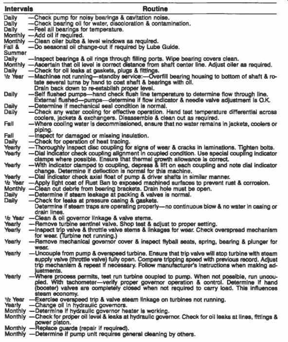
Table 1 Recommended Preventive Maintenance Checks Centrifugal Pumps and
Drivers
==============
Pump Repair
Field Checks Before Removal
Most pump repairs in the petrochemical environment are breakdown repairs as a consequence of component failure. Typical failure causes are:
- Leaking shaft seal
- Reduced pumping rate
- Pump binding or stuck
- Failed bearings
- Excessive vibration
- Leaking casing
The following steps should be taken before the removal of the pump:
1. Check with operator as to perceived failure cause.
2. Run the pump where possible and attempt to diagnose failure by:
- Looking
- Listening
- Feeling
- Smelling
- Measuring bearing temperatures
- Measuring power
- Analyzing vibration
- Measuring flow and pressures
Field Checks During Removal
If diagnosis shows the pump has to be removed, a sequence of field checks will still be appropriate:
1. Check coupling for wear or lack of grease.
2. Visually check oil and oil level.
3. Remove pump, check body gaskets, seats.
4. Visually check impeller and casing wear rings. Also check impeller vs. casing wear ring clearance, check impeller, volutes and balance holes for plugging.
5. Check flush lines and quench lines for internal corrosion or plugging.
6. Visually check condition of gauges, etc.
7. Remove pump to shop for repair.
If failed bearings are suspected in pump or motor:
Check radial clearance and end float in motor.
Run motor and check for abnormal noise, vibration.
If motor is bad, remove and repair.
Diagnosing Pump and Seal Problems
In the Shop
While the pump is being repaired it is advisable to carefully examine every component. A recommended procedure is to match mark all parts prior to disassembly and to make the following checks while dismantling the pump:
1. Visually check impeller and nut for wear, erosion, corrosion and other deterioration.
2. Remove seal flange nuts and check seal tension.
3. Record impeller position in relation to pump frame.
4. Remove impeller nut and impeller.
5. Inspect wear rings inboard, if any.
6. Check and record throttle bushing clearance.
7. Check body gasket faces.
8. Remove stuffing box body from pump frame.
9. Check stuffing box gasket face, bore, and pilots.
10. Remove and inspect all shaft keys.
11. Remove sleeve, seal, sleeve gasket and sleeve flange. If necessary, determine the cause of seal failure and inspect condition of parts.
12. Check pump bearings for roughness. Record shaft end float, check shaft for wear, erosion, corrosion and straightness.
13. Excessive shaft axial end play: Excessive shaft movement can result in pitting, fretting, or wear at points of contact in shaft packing and mechanical seal areas. It can cause over or under-loading on springs resulting in high wear rates and leakage. It can also cause excessive strain and wear on pump bearings. Defective bearings in turn can cause excessive shaft end
To check for this condition a dial indicator should be installed so that its stem bears against the shoulder on the shaft (FIG. 6). Play.
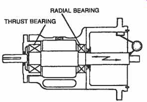
FIG. 6. Checking for end play.
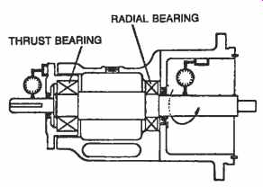
FIG. 7. Checking for bent shaft.
A soft hammer should be used to lightly tap the shaft on one end and then the other. Total indicated end play should be between .001 in. and .004 in. for proper assembly.
14. Bent shaft: When a pump shaft is bent or out of alignment, bearing life, seal life, and performance are impaired. Bent shafts also cause vibration and coupling failures. To check for this condition, install a dial indicator to the pump housing and adjust so that the stem bears on shaft outside diameter. Rotate shaft and check for run-out. If run-out is greater than .002 in. the shaft should be straightened (FIG. 7).
The shaft should be checked in several different locations.
15. Check all pilot fits for concentricity. Also check for excessive shaft radial movement:
Excessive radial shaft movement allows shaft and seal to whip, deflect, and vibrate. This type of movement is caused by improper bearing fit in pump bearing housings or possibly an undersized shaft. If the bearing bore is oversized, determine if it was caused by corrosion, wear or improper machining. To check for this condition, a dial indicator should be placed on the shaft OD as close to the bearings as possible. The shaft should be lifted, or light pressure applied to shaft. If the total movement exceeds .003 in. maximum, bearings and bearing fits should be checked and necessary repairs made (FIG. 8).
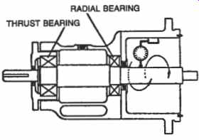
FIG. 8. Checking for whip or deflection.
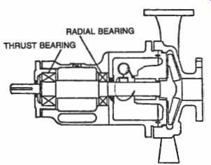
FIG. 9. Checking for stuffing box squareness.
16. Stuffing box squareness:
If the face of the pump stuffing box is not perpendicular to the shaft axis, the mechanical seal gland will tilt when installed. This may cause the seal to wobble and could lead to seal failure.
To check for this condition, clamp a dial indicator to the shaft with the stem against the face of the stuffing box, after the cover has been bolted in place. Total indicator measurement should not exceed .002 in. If face measurement should exceed this tolerance, the cover should be placed in a lathe and machined square. Stuffing box faces should always be checked for pitting, nicks, burrs, and possible erosion before installing the seal (FIG. 9).
17. Check for bore concentricity:
The concentricity of a stuffing box bore and shaft can be difficult to measure because of rust or corrosion due to leaking gaskets.
Concentricity is critical and may have to be reestablished by welding and remachining. On large double-ended pumps where there is a large separation between stuffing boxes it is very important that the concentricity be held to design tolerances.
To check for concentricity, attach a dial indicator to the shaft and sweep as shown in FIG. 10.
Stuffing boxes should be concentric to the shaft axis within .005 in. total indicator reading. If readings are in excess of this, the pump may have to be realigned and re-dowelled.
FIG. 10. Checking for bore concentricity.
18. If bearings are found to be rough or the end float is excessive: Remove pump shaft and bearing from housing.
Remove bearings from shaft.
Check shaft fits, coupling, bearings.
Check shaft straightness and polish lightly.
Clean and check bearing fits in housing.
Repair or replace all faulty and worn parts prior to reassembly.
PREV. | NEXT | Article Index | HOME