AMAZON multi-meters discounts AMAZON oscilloscope discounts
OBJECTIVES
• understand the NEC terminology and requirements for installing all types of residential electrical services.
• calculate the proper size of residential service conductors and raceways.
• understand and install the required grounding and bonding for residential electrical services.
• understand the meaning of the term UFER ground.
• know the NEC requirements for grounding electrical equipment in a separate building.
• calculate the cost of using electricity.
• understand the meaning of conductor withstand rating.
NEC 230.79(C) requires a minimum 100-ampere, 3-wire disconnect for a one-family dwelling. Let's continue with the full details regarding residential electrical services.
This section covers a lot of ground. Mastering the material in this section is quite an accomplishment. Be patient, understanding, and thorough as you tackle it. Congratulate yourself when you have completed this section.
An electric service is required for all buildings containing an electrical system and receiving electrical energy from a utility company. The NEC defines the term service as the conductors and equipment for delivering electric energy from the serving utility to the wiring system of the premises served.
The point where the utility's supply ends and the customer's premises wiring begins is called the Service Point.
The utility company generally must be contacted to determine where they want the meter to be located.
IMPORTANT DEFINITIONS
Several definitions relative to services have changed for the latest NEC. Many of these changes attempt to clarify the portion of the service supply that are the responsibility of the electric utility and which portion is the responsibility of the property owner or installer. The Code defines a service drop as The overhead conductors between the utility distribution system and the Service Point.* These conductors will be installed, owned, and maintained by the electric utility.
A new definition of Overhead Service Conductors was added that reads, Service Conductors, Overhead.
The overhead conductors between the Service Point and the first point of connection to the service-entrance conductors at the building or other structure.* These conductors will be installed by the electrician rather than by the electric utility. However, this rarely happens in practice. The electric utility almost always installs a service drop to the building or structure.
The definition of Service Point in NEC Article 100 is important to our discussion of these issues.
It reads, The point of connection between the facilities of the serving utility and the premises wiring.* This service point establishes the point or line of demarcation between the electric utility and its customer and is most often established by the electric utility. The electric utility is responsible for the conductors and equipment on the supply side of the service point, and the customer is responsible for the electrical conductors and equipment on the load side of the service point. See FIG. 1 for an illustration of these definitions.
Furthermore, NEC 90.2(B)(5) states that the electric utility's service drop is not covered by the NEC. As a result, the title of NEC 230.24 was revised to cover Overhead Service Conductors rather than Service Drops. This section clearly does not apply to the electric utility's service drop, but rather to the customer's overhead service conductors (which are rarely installed). However, NEC 230.26 continues to require the point of attachment for the utility service drop conductors be located so as to provide for the requirements in NEC 230.9 for building openings, and NEC 230.24 for clearances above roofs and above the ground. The bottom line is the point of attachment for the utility's service drop must provide for the NEC-required clearances of overhead service conductors.
OVERHEAD SERVICE
An overhead service includes the service raceways, fittings, meter, meter socket, the main service disconnecting means, and the service conductors between the main service disconnecting means and the point of attachment to the utility's service-drop conductors. Usually, residential-type watt-hour meters are located on the exterior of a building.
In some cases, the entire service-entrance equipment may be mounted outside the building. This includes the watt-hour meter and the disconnecting means.
FIG. 2 illustrates the Code terms for the various components of a service entrance.
Overhead service-drop conductors might be attached to a through-the-roof mast-type service or to the side of the house. In either case, proper clearance is required above the ground, roof, fences, windows, sidewalks, decks, and so on. Locate the mast insulator or screw-in knob so when the electric utility installs the service drop, the clearances above the ground or building features required in NEC 230.24 are met. *Reprinted with permission from NFPA 70-2011.
===
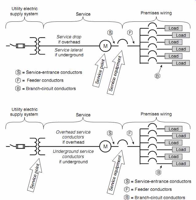
FIG. 1 Definitions from NEC relative to overhead- and underground supplied
services.
===
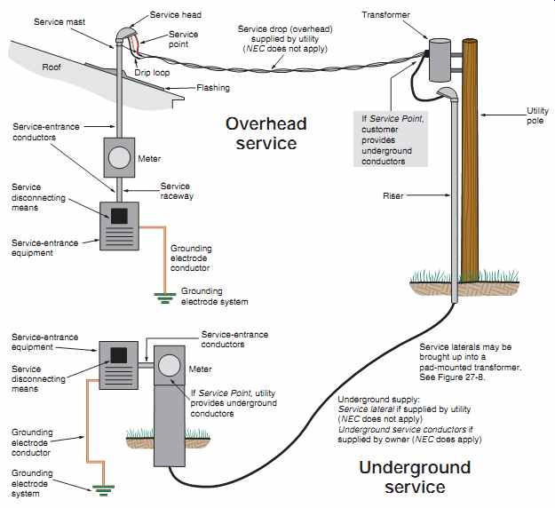
FIG. 2 Code terms for services.
===
MAST-TYPE SERVICE
The mast service, Figures 3, and 4, is a commonly used method of installing an overhead service entrance. The overhead mast service is most commonly used in areas of the electric utility distribution area where the utilities have not been installed underground.
The service raceway is run through the roof, as shown in several figures including 2, 3 and 4, using a roof flashing and neoprene seal fitting, as illustrated in FIGs. 3(A) and 5. This fit ting keeps water from seeping in and damaging the structure where the raceway penetrates the roof. The conduit is securely fastened to the building to comply with Code and electric utility requirements. Many types of fittings are readily available at electrical supply houses for securely fastening raceways and other electrical equipment to wood, brick, masonry, and other surfaces. FIG. 3(B) shows typical methods of securing the conduit mast to ensure it will safely carry the load of the service drop. Several conduit mast fittings are shown in FIG. 5.
Service Mast as Support (230.28)
The bending force on the conduit increases with an increase in the distance between the roof support and the point where the service-drop conductors are attached. The pulling force of a service drop on a mast service conduit increases as the length of the service drop increases. As the length of the service drop decreases, the pulling force on the mast ser vice conduit decreases.
===
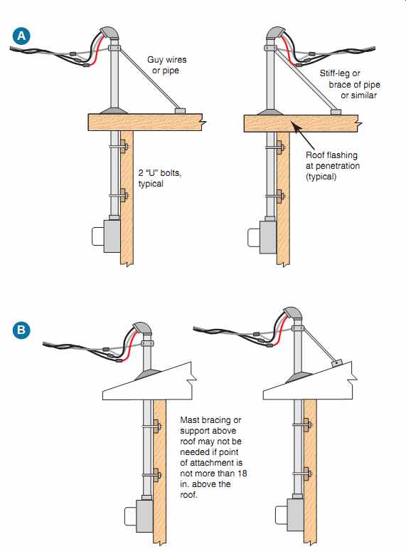
FIG. 3 Typical methods of securing and supporting a mast-type service.
Mast clamp positioned to provide for clearances in NEC 230.24(A) and (B). Follow
electric utility service requirements for all clearances.
===
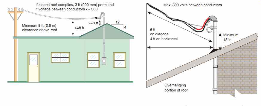
FIG. 4 Clearances of overhead service conductors over roofs.
===

FIG. 5 Fittings for conduit mast include (A) neoprene seal with metal
flashing to use where the service raceway comes through the roof; (B) through-the-wall
support for securing the service raceway; (C) clamp that fastens to the service
raceway to which a guy wires can be attached for support of the service riser;
(D) insulator that can be screwed into a barge rafter or at the gable end of
the building; (E) is an insulating clamp that is fastened to a conduit mast
for terminating the service drop.
===
If extra support is not to be provided, the mast service conduit must be at least 2 in. (50 mm) in diameter. This size prevents the conduit from bending due to the strain of the service-drop conductors.
If extra support is needed, it is usually in the form of guy wires attached to a mast fitting and to the roof in a "Y" configuration. For fairly flat roofs, "stiff legs" made out of galvanized pipe or conduit are often installed from the mast to the roof. FIG. 3 shows several methods for securing conduit masts that are used to support the utility service drop. Some of the hardware that may be used for terminating the service drop is shown in FIG. 5(B), 5(C), 5(E). Again, many support fittings and devices are available at electrical supply houses.
When used as a through-the-roof service mast, rigid metal conduit or intermediate metal conduit is not required to be supported within 3 ft (900 mm) of the service head, 344.30(A) and 342.30(A). Verify the application of this provision with the local electrical inspector and electrical utility, as many utilities have specific installation requirements for securing masts to which their service drop will be attached. The roof mast kit provides adequate support when properly installed.
Clearance Requirements for Service Drop and Overhead Service Conductors for Mast Installations
As stated above, the 2011 NEC significantly changed the requirements for service drops and introduced a new definition for overhead service conductors. Several factors determine the maximum length of conduit that can be installed between the roof support and the point where the service-drop conductors are attached. Verify these factors with the local electric serving utility. Typical requirements are shown in Figures 3 and 4.
The NEC rules for insulation and clearances apply to the service-drop and service-entrance conductors. For example, the service conductors must be insulated, except where the voltage to ground does not exceed 300 volts. In this case, the grounded neutral conductors are not required to have insulation.
Clearance above Roofs: Consult the electric utility that will serve the residence. NEC 230.26 requires that the point of attachment is to provide for the clearances in NEC 230.24(A) for overhead ser vice conductors. The utility service drop is treated as an equivalency to the customer's overhead service conductors. See FIG. 4.
===
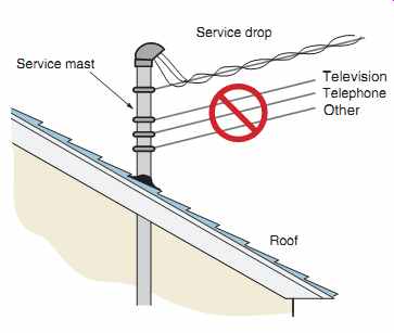
FIG. 6 Only power service-drop conductors are permitted to be attached
to and supported by the service mast. Do not attach or support television cables,
telephone cables, or anything else to the mast, 230.28.
===
Only power service-drop conductors are permit ted to be attached to and supported by the service mast, 230.28. Refer to FIG. 6.
All fittings used with raceway-type service masts must be identified for use with service masts, 230.28.
Consult the utility company and electrical inspection authority for information relating to their specific requirements for clearances, support, and so on, for service masts.
Clearance from Ground: Once again, consult the electric utility that will serve the residence.
NEC 230.26 requires the point of attachment to provide for the clearances in NEC 230.24(B) for the customer's overhead service conductors. These rules give the required clearances for overhead ser vice conductors above ground. See FIG. 7 for clearances.
Clearance from Windows: NEC 230.24(C) refers back to 230.9 to determine the required clearances for service conductors from windows and other building openings. See FIG. 7.
The installation requirements for a typical service entrance are shown in Figures 2, 3, 4, 7, and 8.
Installing Service-Entrance Cable
The installation of service-entrance cable is covered in NEC Article 338. Service-entrance cable for aboveground use is supplied in one of two varieties. A "U" style consists of two insulated conductors with a bare neutral wrapped around the insulated conductors in a spiral configuration. At terminations, the spiral neutral conductor is unwound and twisted together to form the third or neutral conductor. A 4-wire variety of Type SE cable is manufactured and is suitable for installation where a separate neutral and equipment grounding conductor are required, such as for wiring ranges, dryers, and some panels.
As shown in FIG. 9, fittings are specifically designed to facilitate installation of service-entrance cable outside the building. These fittings include a weatherhead and raintight and non-raintight cable clamps. Sill plates are available to protect the cable and weatherproof the installation where the cable is routed inside the building.
===
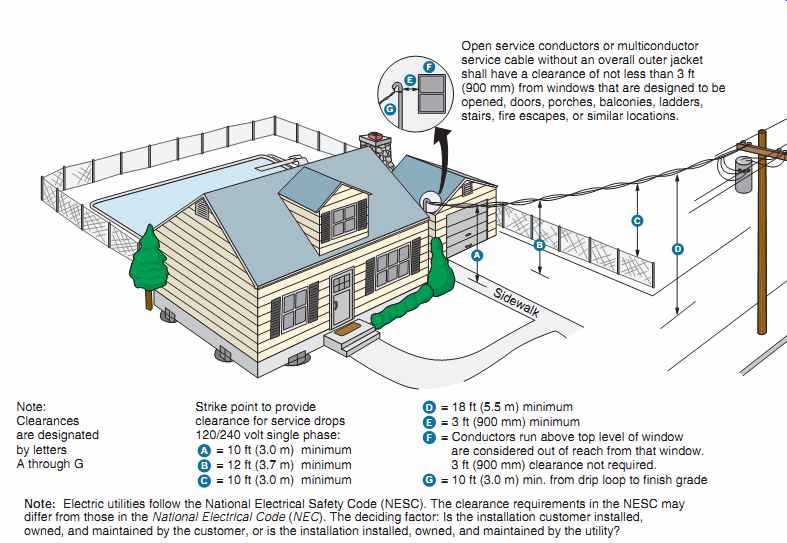
FIG. 7 Clearances from ground for a residential service in accordance
with typical utility requirements. Clearances (A) and (C) of 10 ft (3.0 m)
permitted only if the service-entrance drop conductors are supported on and
cabled together with a grounded bare messenger wire where the voltage to ground
does not exceed 150 volts. This 10-ft (3.0-m) clearance must also be maintained
from the lowest point of the drip loop. Clearance (B) of 12 ft (3.7 m) is permitted
over residential property such as lawns and driveways where the voltage to
ground does not exceed 300 volts.
The circled insert shows clearance from building openings. Open service conductors or multiconductor service cable without an overall outer jacket shall have a clearance of not less than 3 ft (900 mm) from windows that are designed to be opened, doors, porches, balconies, ladders, stairs, fire escapes, or similar locations.
Note: Clearances are designated by letters A through G
Strike point to provide clearance for service drops 120/240 volt single phase:
Note: Electric utilities follow the National Electrical Safety Code (NESC). The clearance requirements in the NESC may differ from those in the National Electrical Code (NEC). The deciding factor: Is the installation customer installed, owned, and maintained by the customer, or is the installation installed, owned, and maintained by the utility?
===
The cable must be protected against physical damage in accordance with NEC 230.50.
Be sure to check with the local electrical inspector, as some jurisdictions limit the length of service entrance cables inside a building. It is considered more fragile than a metal raceway such as EMT, IMC, or rigid steel conduit and requires protection against physical damage in accordance with NEC 300.4.
Verify Which Overhead Clearances Apply
Electricians must abide by the NEC. Utilities must go along with the National Electrical Safety Code. These codes may have different clearance requirements for service-drop conductors and drip loops. When involved with installing an overhead service, check with your electrical inspector to determine which code is enforced in your area.
The installation requirements of the serving electric utility must always be complied with so long as they do not reduce the requirements of the NEC.
UNDERGROUND SERVICE
====
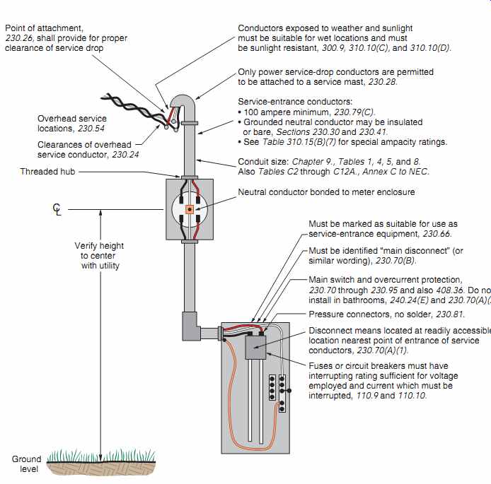
FIG. 8 The wiring of a typical service-entrance installation. Today,
most services are supplied underground, as shown in FIG. 10.
====
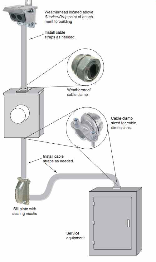
FIG. 9 Typical hardware used for installation of service entrance cable
for services.
===
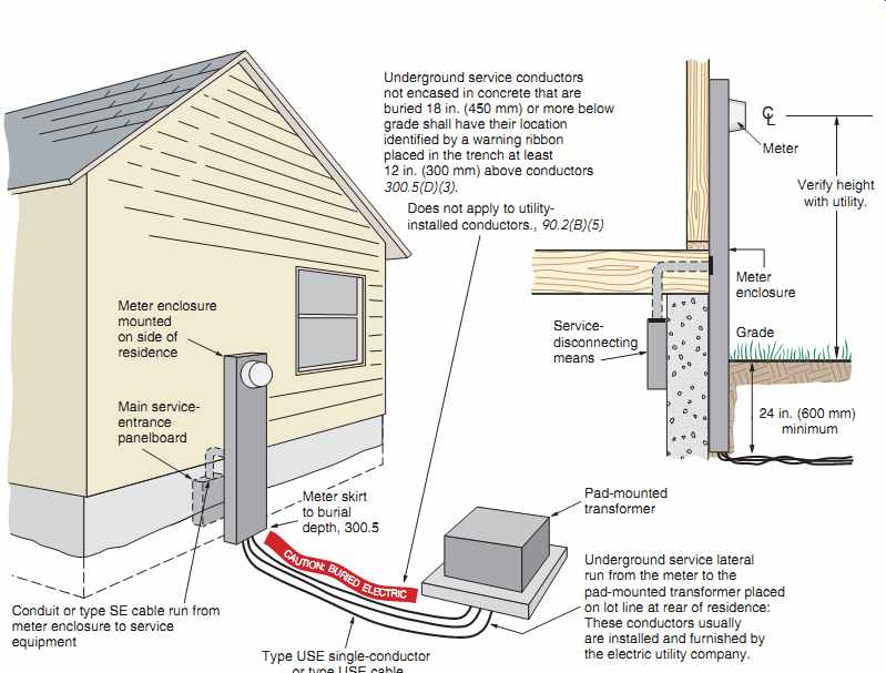
FIG. 10 Underground service.
===
Underground service means the cable installed underground from the point of connection to the system provided by the utility company.
New residential developments often include underground installations of the high-voltage electrical systems. The conductors in these distribution systems end in the bases of pad-mounted transformers, FIG. 10. These transformers are placed at the rear lot line or in other inconspicuous locations in the development. The transformer and primary high voltage conductors are generally installed by, and are the responsibility of, the utility company.
If installed by the electric utility, the conductors installed between the pad-mounted transformer and the meter are called service lateral conductors.
Normally, the electric utility furnishes and installs them. In many areas, the utility will install both the service lateral conductors and the communication cables in the same trench. In some areas, but not too commonly, service laterals, communication cables, and gas lines are run in the same trench. FIG. 10 shows a typical underground installation.
The wiring from the external meter to the main ser vice equipment is the same as the wiring for a service connected from overhead lines, as in FIG. 8.
Some local codes may require conduit to be installed underground from the pole to the service-entrance equipment. NEC requirements for underground ser vices are given in Article 230, Part III. If installed by the owner or electrician, the underground conductors must be suitable for direct burial in the earth, Type USE single-conductor or Type USE cable containing more than one conductor, NEC Article 338.
If the electric utility installs the underground service conductors, the work must comply with the rules established by the utility. Utilities follow the National Electrical Safety Code, NESC. These rules may not be the same as those given in NEC 90.2(B)(5).
As stated in NEC 90.2(B)(5), the NEC does not cover installations under the exclusive control of an electric utility where such installations:
a. consist of service drops or service laterals and associated metering, or
b. are on property owned or leased by the electric utility for the purpose of communications, metering, generation, control, transformation, transmission, or distribution of electric energy, or
c. are located in legally established easements, rights-of-way, or
d. are located by other written agreements either designated by or recognized by public ser vice commissions, utility commissions, or other regulatory agencies having jurisdiction for such installations. These written agreements shall be limited to installations for the purpose of communications, metering, generation, control, transformation, transmission, or distribution of electric energy where legally established easements or rights-of-way can not be obtained. These installations shall be limited to Federal Lands, Native American Reservations through the U.S. Department of the Interior Bureau of Indian Affairs, military bases, lands controlled by port authorities and State agencies and departments, and lands owned by railroads.
When underground service conductors or service-entrance cables are installed by the electrician, 230.50 applies. This section deals with the protection of service-entrance conductors and service entrance cables against physical damage. NEC 230.50 also refers to 300.5, which covers all situations involving underground wiring, such as the sealing of raceways where they enter a building. Sealing raceways is covered in "Meter/Meter Base Location" later on in this section.
MAIN SERVICE DISCONNECT LOCATION
In conformance to 230.70(A)(1) and 230.70(A)(2), the main service disconnecting means shall
• be located inside the building at a readily accessible location nearest the point of entrance of the service conductors, FIG. 11, or
• be located outside the building at a readily accessible location, and
• not be installed in a bathroom.
If for some reason it is necessary to locate service-entrance equipment some distance inside the building, NEC 230.6 considers service-entrance conductors to be outside of a building if the service-entrance conductors are one of the following:
• installed under not less than 2 in. (50 mm) of concrete beneath the building, or
• installed within the building in a raceway encased in at least 2 in. (50 mm) of concrete or brick, or
• installed in conduit, and covered by at least 18 in. (450 mm) of earth beneath the building.
===
Service disconnecting means to be readily accessible and nearest the point where the service-entrance conductors enter the building.
Consult with electrical inspector to determine whether greater lengths inside the building are permitted.
This switch is not as close as possible to the point where the service-entrance conductors enter the building.
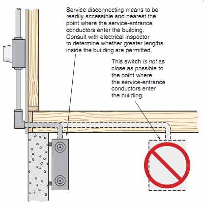
FIG. 11 Main service disconnect location, 230.70. Do not install in a
bathroom. Refer to 230.70(A)(2) and 240.24(E).
===
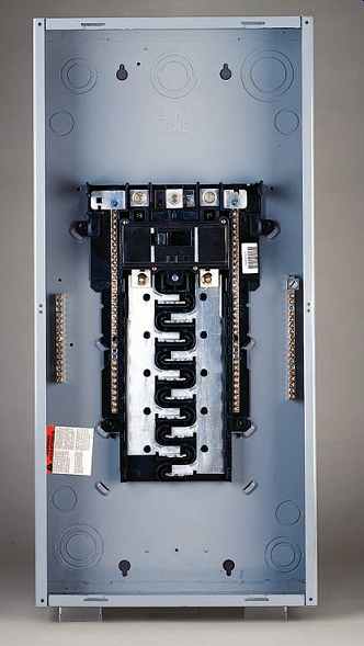
FIG. 12 A typical 120/240-volt, single-phase, 3-wire load center. This
load center has a main circuit breaker. Note the neutral terminal bars for
termination of the white branch-circuit grounded conductors, and the equipment
grounding terminal bars for termination of the equipment grounding conductors
of nonmetallic-sheathed cable. See 230.66. (Schneider Electric)
====
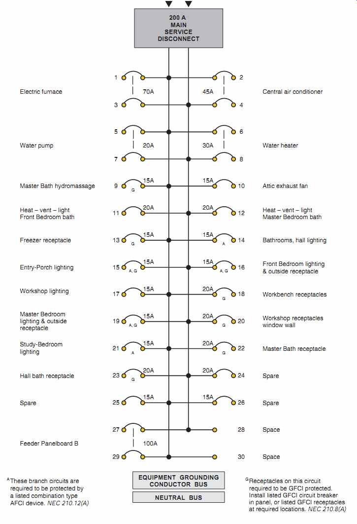
FIG. 13 Circuit schedule of Main Service Panel A.
====
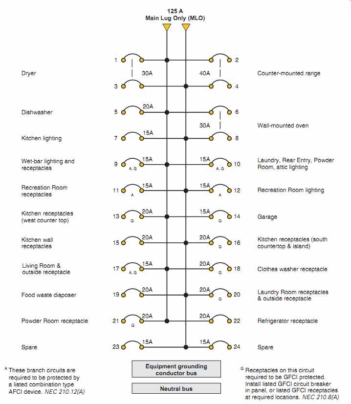
FIG. 14 Circuit schedule of Panelboard B.
====
Circuit Directory/Circuit Identification
NEC 408.4 is very clear as to its requirements on the subject. It requires that Every circuit and circuit modification shall be legibly identified as to its clear, evident, and specific purpose or use. The identification shall include sufficient detail to allow each circuit to be distinguished from all others. Spare positions that contain unused overcurrent devices or switches shall be described accordingly. The identification shall be included in a circuit directory that is located on the face or inside of the panel door in the case of a panel board, and located at each switch on a switchboard. No circuit shall be described in a manner that depends on transient conditions of occupancy.* FIG. 12 shows a typical 240/120-volt, single-phase, 3-wire panelboard.
FIG. 13 shows the circuit identification for Main Service Panel A. FIG. 14 shows the circuit identification for sub-Panel B.
NEC 110.22 also required that disconnect switches be "legibly marked," describing what the disconnect is for.
*Reprinted with permission from NFPA 70-2011.
Service Disconnecting Means (Panel A)
It is extremely important that a disconnect or panelboard used as service equipment be marked "Suitable for Use as Service Equipment." This is a requirement of 230.66. Some disconnects and panel boards are so marked-others are not. Such marking ensures that proper bonding together of the neutral bus, equipment ground bus, and metal enclosure is provided, as well as a termination (lug) for the grounding electrode conductor.
More requirements for service disconnect means are found in 230.70 through 230.82. NEC 230.71(A) requires that the service disconnecting means consist of not more than six switches or six circuit breakers mounted in a single enclosure, in a group of separate enclosures in the same location, or in or on a switchboard. This permits the disconnection of all electrical equipment in the house with not more than six hand operations. Some local codes take exception to the six-disconnect rule, and require a single main disconnect. Some localities require the main disconnecting means to be located outside. If located outside, 230.70(A)(1) requires that the ser vice disconnect must be located on the building, and must be readily accessible.
You need to check this out with the local authority that has jurisdiction in your area.
In damp and wet locations, to prevent the accumulation of moisture that could lead to rusting of the enclosure and damage to the equipment inside the enclosure, 312.2 specifies that there be at least a 1/4-in. (6-mm) air space between the wall and a surface mounted enclosure. Most disconnect switches, panelboards, meter sockets, and similar equipment have raised mounting holes that provide the necessary clearance. This is clearly visible in the open-meter socket in FIG. 15 of the "Meter/Meter Base Location" section in this section. The NEC (in Definitions) considers masonry in direct contact with the earth to be a wet location. The Exception to 312.2 allows nonmetallic enclosures to be mounted without an air space on concrete, masonry, tile, and similar surfaces.
Panelboards shall be installed in accordance with the listing of the panelboard. A panelboard used as service equipment that has multiple overcurrent devices is not required to have overcurrent protection on the line side of the panelboard, 408.36, Exception No. 1. When used as other than service equipment, overcurrent protection for the panelboard shall not exceed the rating of the panelboard.
NEC 230.79 tells us that the service disconnect shall have a rating not less than the calculated load to be carried, determined in accordance with Parts III, IV, or V of Article 220. We show how these calculations are made in Section 29.
For a one-family residence, the minimum size main service disconnecting means is 100 amperes, 3-wire, NEC 230.79(C).
NEC 230.70(B) requires that the main service disconnect must be permanently marked to identify it as service disconnect.
When nonmetallic-sheathed cable is used, a panel board must have a terminal bar for attaching the equipment grounding conductors, 408.20. See FIG. 16.
For this residence, panelboard A serves as the main disconnecting means for the service. This panelboard consists of a main circuit breaker and many branch-circuit breakers. FIG. 12 is a photo of this type of panelboard. FIG. 13 is the schedule of the circuits connected to panelboard A. Panelboard A is located in the Workshop.
Working Space. To provide for safe working conditions around electrical equipment, 110.26 contains a number of rules that must be followed. For residential installations, there are some guidelines for working space.
• A working space not less than 30 in. (762 mm) wide and 3 ft (914 mm) deep must be provided in front of electrical equipment, such as panel boards A and B in this residence.
• This working space must be kept clear and not used for storage.
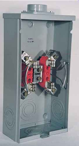
FIG. 15 Typical residential self-contained meter socket. Combination
meter socket/main breaker in one enclosure is also available. (Schneider Electric)
• Do not install electrical panelboards inside of cabinets, nor above shelving, washers, dryers, freezers, work benches, and so forth.
• Do not install electrical panels in bathrooms.
• Do not install electrical panels above or close to sump pump holes.
• The hinged cover (door) on the panel shall be able to be opened to a full 90°.
• A "zone" equal to the width and depth of the electrical equipment, from the floor to a height of 6 ft (1.8 m) above the equipment or to the structural ceiling, whichever is lower, shall be dedicated to the electrical installation. No piping, ducts, or equipment foreign to the electrical installation shall be located in this zone. This zone is dedicated space intended for electrical equipment only! See 110.26(E).
Mounting Height. Disconnects and panelboards must be mounted so the center of the main disconnect handle in its highest position is not higher than 6 ft 7 in. (2.0 m) above the floor, 404.8.
Headroom. To provide for safe adequate working space and easy access to service equipment and electrical panels, the NEC in 110.26(A)(3) requires that there be at least 6½ ft (2.0 m) of headroom. If you are installing service equipment in an existing dwelling, services of 200 amperes or less are permit ted to be located in areas where the headroom is less than 6 1/2 ft (2.0 m).
====
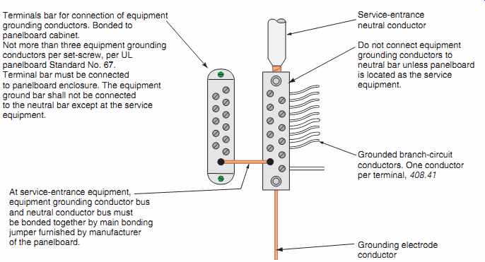
FIG. 16 Connections of service neutral conductor, branch-circuit neutral
conductors, and equipment grounding conductors at panelboards, 408.40 and 408.41.
====
Lighting Required for Service Equipment and Panels. Working on electrical equipment with inadequate lighting can result in injury or death. In 110.26(D), there is a requirement that illumination be provided for service equipment and panelboards. But the Code does not spell out how much illumination is required. It becomes a judgment call on the part of the electrician and/or electrical inspector. Note that the electrical plans for the workshop show a porcelain pull-chain lampholder to the front of and off to one side of the main service panelboard A. In many cases, adjacent lighting, such as the fluorescent luminaires in the recreation room, is considered to be the required lighting for equipment such as panelboard B.
Panelboard Setback in Walls
Panelboards are sometimes installed within a wall for flush mounting. The setback and repair opening rules for panelboards are found in NEC 312.3 and 312.4:
• In plaster, drywall, or plasterboard: repair wall so no gap or opening is greater than 1/8 in. (3 mm).
• In combustible walls: flush.
• In wall of concrete, tile, or other noncombustible material: set back not more than 1/4 in. (6 mm).
Close Openings in Panelboards
Inside a panelboard, there are live parts! There is a real fire and shock hazard when there are openings (knockouts) on the sides, top, or bottom of a panel board or when circuit breaker openings in the cover are inadvertently broken out.
NEC 408.7 requires that Unused opening for circuit breakers and switches shall be closed using identified closures, or other approved means that provide protection substantially equivalent to the wall of the enclosure.* Identified means Recognizable as suitable for the specific purpose, function, use, environment, application, and so forth, where described in a particular Code requirement.* Approved means Acceptable to the authority having jurisdiction.*
===
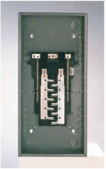
FIG. 17 Typical 240/120-volt, single-phase, 3-wire panelboard, sometimes
called a load center. This panelboard does not have a main disconnect and is
referred to as a main lug only (MLO) panel. The branch-circuit breakers are
not shown. This is the type of panelboard that could be used as panelboard
B in the residence discussed in this text. Most panelboards have a separate
terminal bar on which to terminate the equipment grounding conductors of nonmetallic
sheathed cable, as in FIG. 12.
====
Panelboard B
When a second panelboard is installed, it is oftentimes called a subpanel.
For installation where the main service panel board is a long distance from areas that have many circuits and/or heavy load concentration, as in the case of the kitchen and laundry of this residence, it is recommended that at least one additional panel be installed near these loads. This results in the branch-circuit wiring being short. Line losses (voltage and wattage) are considerably less than if the branch circuits had been run all the way back to the main panelboard.
The cost of material and labor to install an extra panelboard should be compared to the cost of running all of the branch-circuit "home runs" back to the main service panelboard.
Panelboard B in this residence is located in the Recreation Room. It is fed by three 3 AWG THHN or THWN conductors run in a trade size 1 EMT originating at the service (panelboard A). This feeder is protected by a 100-ampere, 2-pole circuit breaker located in panelboard A.
Do not install panelboards in clothes closets, 240.24(D). There is a fire hazard because of the presence of ignitable materials.
Do not install panelboards in bathrooms, 240.24(E). Damaging moisture problems may result from the presence of water, and shock hazard may result from both the presence of water and the close proximity of metal faucets, and other plumbing fixtures.
Panelboard B is shown in FIG. 17. The circuit schedule for panelboard B is found in FIG. 14.
SERVICE-ENTRANCE RACEWAY SIZING
This residence is served with an underground ser vice. The conduit running from the meter to Main panelboard A must be sized correctly for the conductors it will contain. In the case of a through-the roof mast service, the conduit might be sized for both mechanical strength reasons and conductor fill. All utilities have requirements for size and guying of mast services. Table 1 shows the calculation for sizing the service-entrance conduit.
SERVICE-ENTRANCE CONDUCTOR SIZING
NEC 230.42(A) states that the minimum size service entrance conductors must be of sufficient size to carry the load as calculated according to Article 220.
NEC 230.79(C) calls for a minimum service of 100 amperes for a one-family residence.
The standard and optional methods for calculating the minimum size of service-entrance conductors are discussed in detail in Section 29.
RUNNING CABLES INTO TOP OF SERVICE PANEL
See Figure 4-21 for running nonmetallic-sheathed cables into the top of a panelboard.
SERVICE-ENTRANCE OVERCURRENT PROTECTION
Overcurrent protection (fuses and circuit breakers) is discussed in Section 28.
=======
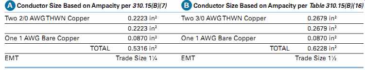
TABLE 1
Calculations for sizing the EMT between Main Panelboard A and the meter base. (A) uses the smaller size conductors permitted by 310.15(B)(7). (B) uses conductors sized per the standard calculations.
=======
METER/METER BASE LOCATION
The electric utility must be contacted before the installation of the service equipment begins.
The utility will determine when, where, and how the connection will be made to the homeowner's service conductors. Because of the ever-increasing number of wood decks and concrete patios being added to homes, many utilities prefer that the meter be mounted on the side of the house rather than in the rear. If there is a raised deck, the meter could be only a short distance above the deck, making it both subject to physical damage and hard to read. If concrete patios are poured over underground utility cables, it is very difficult to repair or replace these cables should there be problems. Utilities furnish manuals and brochures detailing their requirements for services that are not found in the NEC.
The electric utility furnishes and installs the watt hour meter. The meter base, also referred to as a meter socket, is usually furnished and installed by the electrical contractor, although some utilities furnish the meter base to the electrical contractor for installation.
FIG. 7 shows a service supplied from an underground service. FIG. 11 discusses the requirement that the main disconnect must be as close as possible to the point of entrance of the service-entrance conductors. FIG. 15 shows a typical meter socket for an overhead service, usually mounted at eye level on the outside wall of the house.
The service raceway or service-entrance cable is connected to the threaded hub (boss) on top of the meter socket. FIG. 18 shows how to seal the raceway where it enters the building, to keep out moisture.
A combination meter socket/main breaker in one enclosure is also available.
Rain-tight and Draining Outdoor locations are generally wet locations.
However, under an overhang may be considered a damp rather than a wet location. If you are using EMT outdoors in a wet location, the fittings (couplings and connectors) must be listed as "Raintight." If the fit tings and the container they come in are not marked "Rain-tight," then the fittings have not been listed for rain-tight applications. Rain-tight fittings are generally of the compression type that has a special sealing ring.
NEC 225.22 states that Raceways on exteriors of buildings or other structures shall be arranged to drain and shall be rain-tight in wet locations.* NEC 230.53 states that Where exposed to the weather, raceways enclosing service-entrance conductors shall be rain-tight and arranged to drain.
Where embedded in masonry, raceways shall be arranged to drain.*
===
Inside Outside Sealant
NEC 300.5(G) and 300.7 state that when raceways pass through areas having great temperature differences, some means must be provided to prevent passage of air back and forth through the raceway. Note that outside air is drawn in through the conduit whenever a door opens.
Cold outside air meeting warm inside air causes the condensation of moisture. This can result in rusting and corrosion of vital electrical components. Equipment having moving parts, such as circuit breakers, switches, and controllers, is especially affected by moisture. The sluggish action of the moving parts in this equipment is undesirable.
Sealant shall be identified for such use, and shall not have an adverse effect on the conductor insulation, 230.8.
NEC 230.8 requires seals where service raceways enter from an underground distribution system.
FIG. 18 Installation of conduit through a basement wall.
===
The electric utility provides the underground service lateral.
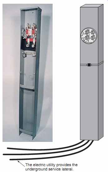
FIG. 19 Installing a metal "pedestal" allows for ease of installation
of the underground service-entrance conductors by the utility.
===
Pedestals
Meter "pedestals," as shown in FIG. 19, are sometimes used for residential services. Usually mounted on the outside wall of the house, a meter "pedestal" could also be installed on the lot line between residential properties. Contact the electric utility on this issue.
For underground services, the utility generally runs the underground lateral service-entrance conductors in a trench from a pad-mount transformer to the line-side terminals of the meter base. The electrician then takes over to complete the service installation by running service-entrance conductors from the load side of the meter to the line side of the main service disconnect.
Quite often, the electric utility and the telephone company have agreements whereby the electric utility will lay both power cables and telephone cables in the same trench. The electric utility carries both types of cables on its underground installation vehicles. This is a much more cost-effective way to do this than having each utility dig and then backfill its own trenches.
Often overlooked is a requirement in NFPA Standard No. 54 (Fuel Gas Code), Section 2.7.2(c), requiring that gas meters be located at least 3 ft (900 mm) from sources of ignition. Examples of sources of ignition might be an air-conditioner disconnect where an arc can be produced when the disconnect is opened under load. Furthermore, some electric utilities require a minimum of 3 ft (900 mm) clearance between electric metering equipment and gas meters and gas regulating equipment. It is better to be safe than sorry. Check this issue with the local electrical inspector if there might be a problem with the installation you are working on.
COST OF USING ELECTRICAL ENERGY
A watt-hour meter is always connected into some part of the service-entrance equipment to record the amount of energy used. Billing by the utility is generally done on a monthly basis. The meter might be mounted on the side of the house or on a pedestal somewhere on the premise on the lot line. The utility makes this decision. The residence discussed in this text has one meter, mounted on the back of the house near the sliding doors of the Master Bedroom.
The kilowatt (kW) is a convenient unit of electrical power. One thousand watts (w) is equal to one kilowatt. The watt-hour meter measures and records both wattage and time.
For residential metering, most utilities have rate schedules based on "cents per kilowatt-hour." Stated another way: How much wattage is being used and for how long? Burning a 100-watt light bulb for 10 hours is the same as using a 1000-watt electric heater for 1 hour. Both equal 1 kilowatt-hour.
kWh = watts x hours/1000 = 100 x 10/1000 = 1 kWh
kWh = watts x hours / 1000 = 1000 x 1/1000 =1 kWh
In these examples, if the electric rate is $0.08 cents per kilowatt-hour, the cost to operate the 100 watt light bulb for 10 hours and the cost to operate the electric heater for 1 hour are the same--$0.08.
Both loads use 1 kilowatt-hour of electricity.
Note: The answers to these examples are approximate because they were based on watts. Power factor and efficiency factors were not included as they generally are unknown when making rough estimates of an electric bill. For all practical purposes, the answers are acceptable.
Table 2 is an example of what a typical monthly electric bill might look like.
Some utilities increase their rates during the hot summer months, when the air-conditioning load is high. Other utilities provide a second meter for specific loads such as electric water heaters, air conditioners, heat pumps, or total electric heat. Other utilities use electronic watt hour meters that have the capability of registering kilowatt-hour consumption during a specific "time of use." These electronic watt-hour meters might have up to four different "time-of-use" periods, each period having a different "cents per kilowatt-hour" rate.
Other charges that might appear on a "light bill" might be a fuel adjustment charge based on a "per kWh" basis. Such charges enable a utility to recover from the consumer extra expenses it might incur for fuel costs used in generating electricity. Fuel charges can vary with each monthly bill, without the utility having to apply to the regulatory agency for a rate change.
===
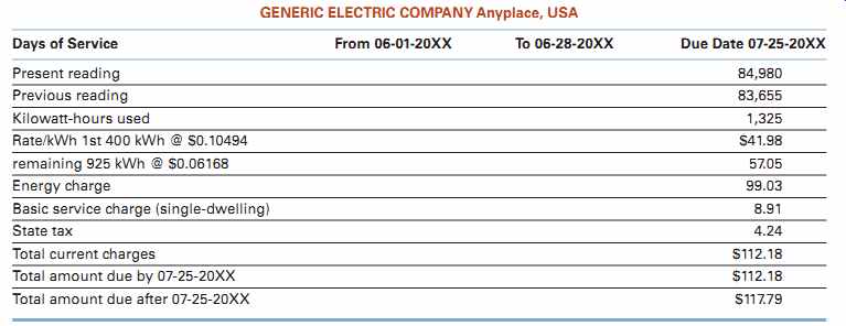
TABLE 2: A typical monthly electric bill.
===
GROUNDING/BONDING (ARTICLE 250)
All residential electrical systems are grounded systems. Within the system, some things are grounded and some things are bonded. The terms grounding and bonding are used throughout the NEC. There is a distinct difference between grounding and bonding. Each serves a different purpose. Let's take a look at these two very important terms.
What Does Grounded (Grounding) Mean?
Grounded (grounding) is defined in NEC Article 100 as Connected to ground or to a conductive body that extends the ground connection.* See FIG. 20. As shown, the electrical system is grounded by the electric utility at the transformer and again at the service equipment.
What Does Bonded (Bonding)
Mean? Bonded (bonding) is defined in NEC Article 100 as Connected to establish electrical continuity and conductivity.* See FIG. 21. In its simplest form, bonding means "connected together." Now that we have talked about the meaning of the words "grounding" and "bonding," here are more detailed definitions you should be familiar with.
===
Grounding electrode
Main bonding jumper Grounding electrode conductor Neutral bus Neutral point Source of electrical system Service equipment Grounded neutral service conductor Earth FIG. 20 Grounding of an electrical system at the utility transformer and at the service connects the electrical system to earth.
===
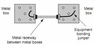
FIG. 21 Two methods for bonding the metal boxes or other metal parts
together. One method uses the metal raceway. The second method is to install
a separate equipment grounding conductor between the two metal boxes, as would
be required if a nonmetallic raceway had been used.
Metal raceway between metal boxes Metal box Metal box Equipment bonding jumper
===
GROUNDING
The following definitions related to grounding are found in NEC Article 100, 250.2, and 250.4(A).
Ground: The Earth.* Throughout this country and, for that matter, throughout the world, the earth is the common reference point for all electrical systems.
Grounded Conductor: A system or circuit conductor that is intentionally grounded.* In residential wiring, this is the white conductor. It is also referred to as the neutral conductor.
Grounding Conductor, Equipment (EGC):
The conductive path(s) installed to connect normally non-current-carrying metal parts of equipment together and to the system grounded conductor or to the grounding electrode conductor, or both.* The definition speaks of connecting equipment together.
When you think about it, it is logical to conclude that the equipment grounding conductor also functions as a bonding conductor. In residential wiring, the equipment grounding conductor is the bare conductor in nonmetallic-sheathed cable, the metal jacket plus the bonding strip in armored cable, metal raceways, green insulated conductors, and so on.
Different acceptable EGCs are listed in 250.118.
Size the EGC per Table 250.122.
EGCs are illustrated in Figures 5-30, 5-32, 5-33, 5-34, 16, and 30-4.
Ground Fault: An unintentional, electrically con ducting connection between a normally current-carrying conductor of an electrical circuit, and the normally non current-carrying conductors, metallic enclosures, metallic raceways, metallic equipment, or earth.* Ground faults occur when an ungrounded "hot" conductor comes in contact with a grounded surface or grounded conductor. This could be a result of insulation failure or an ungrounded conductor connection coming loose.
Ground-Fault Current Path: An electrically conductive path from the point of a ground fault on a wiring system through normally non-current-carrying conductors, equipment, or the earth to the electrical supply source.* This is the path that the flow of ground-fault current will take. Whatever fault current flows, that fault current must return to its source.
What goes out must come back! The current might return through connectors, couplings, bonding jumpers, grounding conductors, ground clamps, and other components that make up the ground-fault return path.
Ground-Fault Current Path, Effective: As defined in 250.2, An intentionally constructed,
reliable, low-impedance electrically conductive path designed and intended to carry current under ground-fault conditions from the point of a ground fault on a wiring system to the electrical supply source and that facilitates the operation of the overcurrent protective device or ground fault detectors on high impedance grounded systems.* If and when a ground fault occurs, we want the overcurrent device ahead of the ground fault to open as fast as possible to clear the fault. To accomplish this, the integrity of the ground fault current path must be unquestionable.
We sometimes think that electricity follows the path of least resistance. That is not totally correct! Electricity follows all paths. As stated earlier, ground-fault current might return through connectors, couplings, bonding jumpers, grounding conductors, ground clamps, and any other components that make up the ground-fault return path. Some of the fault cur rent might flow on sheet metal ductwork and on metal water piping or metal gas piping. That is why the NEC is so strict about keeping the impedance of the ground-fault current path as low as possible. We want the ground-fault current to return on the electrical sys tem-not on other nonelectrical parts in the building.
Think about it this way-the lower the impedance, the higher the current flow. The higher the current flow, the faster the overcurrent device will clear the fault.
As required by 250.4(A)(5), Electrical equipment and wiring and other electrically conductive material likely to become energized shall be installed in a manner that creates a low-impedance circuit facilitating the operation of the overcurrent device or ground detector for high-impedance grounded systems. It shall be capable of safely carrying the maximum ground-fault current likely to be imposed on it from any point on the wiring system where a ground fault may occur to the electrical supply source. The Earth shall not be considered as an effective ground-fault current path.* Grounding Electrical System: Electrical systems that are grounded shall be connected to earth in a manner that will limit the voltage imposed by lightning, line surges, or unintentional contact with higher voltage lines and that will stabilize the voltage to earth during normal operation.* See FIG. 20.
Grounding of Electrical Equipment: Normally non-current-carrying conductive materials enclosing electrical conductors or equipment, or forming part of such equipment, shall be connected to earth so as to limit the voltage to ground on these materials.* Grounding Electrode: A conducting object through which a direct connection to earth is established.* In residential wiring, the grounding electrode might be an underground metal water piping supply, a concrete-encased reinforcing steel bar or bare copper conductor (UFER ground), or it might be a ground rod(s). Acceptable grounding electrodes are listed in 250.52(A)(1) through (7). See 250.52.
Grounding Electrode Conductor: A conductor used to connect the system grounded conductor or the equipment to a grounding electrode or to a point on the grounding electrode system.* See 250.62. For typical residential wiring, the grounding electrode conductor is run between the main service panel neutral/ground terminal bar and the grounding electrode system.
Grounding electrode conductors
• are permitted to be aluminum or copper [see the limitation on the installation of aluminum conductors in 250.64(A)].
• shall be protected against physical damage, 250.64(B).
• If required, splices or connections shall be made as permitted in parts (1) through (4) of 250.64(C).
• (1) Splicing of the wire-type grounding electrode conductor shall be permitted only by irreversible compression-type connectors listed as grounding and bonding equipment or by the exothermic welding process.
• (2) Sections of busbars shall be permitted to be connected together to form a grounding electrode conductor.
• (3) Bolted, riveted, or welded connections of structural metal frames of buildings or structures
• (4) Threaded, welded, brazed, soldered or bolted-flange connections of metal water piping are sized according to Table 250.66.* In this residence, a 4 AWG armored copper grounding electrode conductor (GEC) runs from Main Panel A, across the workshop ceiling to the water pump area. The GEC is terminated with a listed ground clamp to the metal water piping where the piping comes through the basement wall. Depending on the size of the metal water pipe, ground clamps of the types illustrated in FIGs. 22, 23, 24, and 25 are used. As previously mentioned, because of the ever-increasing use of nonmetallic water pipe, there is a corresponding decrease in the use of a water pipe grounding electrode and more use of the concrete-encased grounding electrode, referred to as the UFER ground. To comply with the requirements in NEC 250.50 to create a grounding electrode system, a 4 AWG copper bonding conductor was connected to a 20-ft (6.0 m) section of the reinforcing steel bar in the foundation footing before the concrete was poured. The end of the bonding conductor was coiled and left in the area of the water pipe so the two grounding electrodes could be bonded together.
===
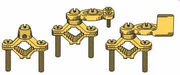
FIG. 22 Typical ground clamps used in residential systems.
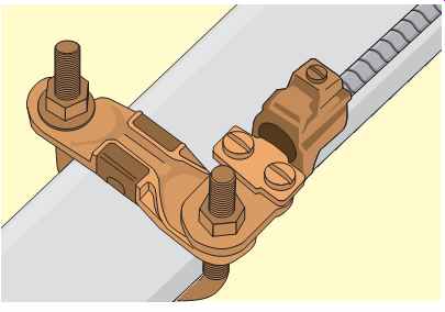
FIG. 23 Armored grounding conductor connected with ground clamp to water
pipe. (Thomas & Betts)
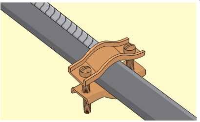
FIG. 24 Ground clamp of the type used to bond (jumper) around water meter.
(Thomas & Betts)
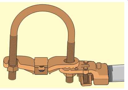
FIG. 25 Ground clamp of the type used to attach ground wire to well casings.
(Thomas & Betts)
===
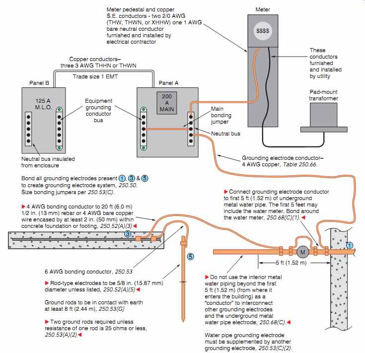
FIG. 26 A typical electrical service grounded to a grounding electrode
system consisting of an underground metal water piping supply, concrete-encased
electrode, and ground rod.
===
Reference to grounding electrode conductors is found in FIGs. 2, 16, 20, 26, 27, 28, and 29 through 34.
Ungrounded: Not connected to ground or a conductive body that extends the ground connection.*
BONDING
The following definitions related to bonding are found in NEC Article 100.
Bonded (Bonding): Connected to establish electrical continuity and conductivity.* FIG. 21 shows two metal boxes bonded together with the metal raceway installed between the two boxes. The bonding jumper could also have been a conductor.
Requirements for the size of a conductor of the wire type are found at various locations in Article 250.
Bonding Conductor or Jumper: A conductor to ensure the required electrical conductivity between metal parts required to be electrically connected.* A conductor of the wire type is required to be installed in a nonmetallic raceway to provide continuity between metal parts. With a metal race way, the bonding would be accomplished by the metal raceway.
===
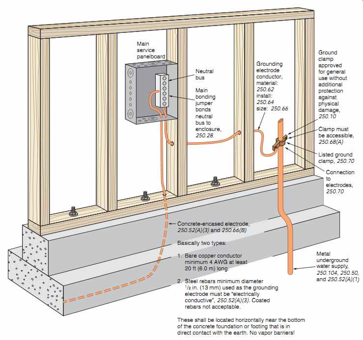
FIG. 27 Connection of concrete-encased grounding electrode and underground
metal water pipe.
===
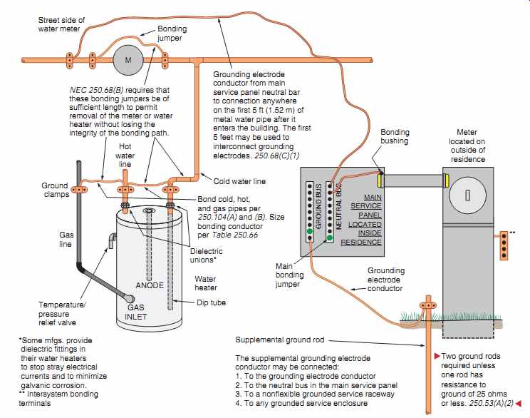
FIG. 28 One method that may be used to provide proper electrical system
grounding of service-entrance equipment, and bonding of the cold and hot water
piping and gas piping.
**Provide a listed intersystem bonding terminal strip at the meter enclosure, service equipment enclosure, or on the grounding electrode conductor.
===
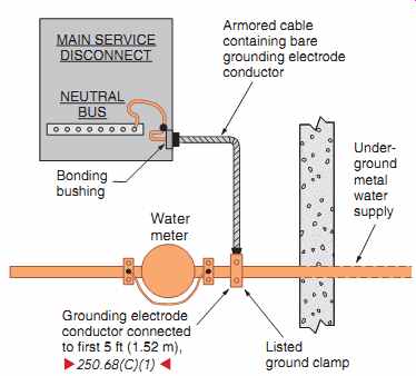
FIG. 29 This installation "Meets Code."
===
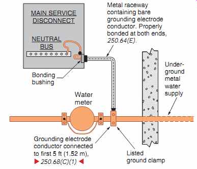
FIG. 30 This installation "Meets Code."
===
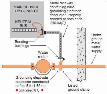
FIG. 31 This installation "Meets Code."
===
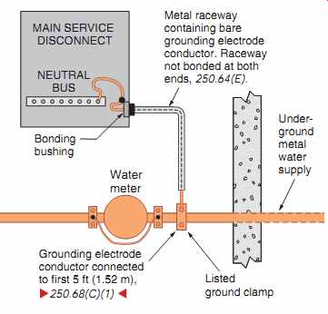
FIG. 32 This installation does not "Meet Code."
===
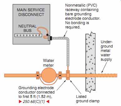
FIG. 33 This installation "Meets Code."
===
Bonding Jumper, Equipment: The connection between two or more portions of the equipment grounding conductor.* Bonding equipment together does not mean that the equipment is grounded.
However, typical electrical systems in residential occupancies are grounded. The equipment grounding conductor then serves a dual function of bonding metal enclosures together and providing a ground fault return path back to the source.
Bonding Jumper, Main: The connection between the grounded circuit conductor and the equipment grounding conductor at the service. See 250.28.
Main bonding jumpers are clearly illustrated in FIGs. 8, 16, 20, 26, and 28.
Bonding of Electrically Conductive Materials and Other Equipment: Normally non-current carrying electrically conductive materials that are likely to become energized shall be connected together and to the electrical supply source in a manner that establishes an effective ground-fault current path. NEC 250.4(A)(4).*
Bonding of Electrical Equipment: Normally non-current-carrying conductive materials enclosing electrical conductors or equipment, or forming part of such equipment, shall be connected together and to the electrical supply source in a manner that establishes an effective ground-fault current path.
NEC 250.4(A)(3).* These are a few other key Code sections relating to system grounding:
250.20(B)(1): This section requires that an electrical system be grounded where the maximum volt age to ground on the ungrounded "hot" conductors does not exceed 150 volts. The serving electric utility grounds the midpoint of their transformer. This midpoint becomes the system neutral point.
The electrical system in a typical home is single-phase, 3-wire, 120/240 volts. The voltage between the ungrounded "hot" phase conductors is 240 volts, and the voltage between the ungrounded "hot" phase conductors and the neutral (the grounded conductor) is 120 volts. The grounded neutral service conductor is again grounded at the main service.
The electrical system in some large multi family buildings (condos, apartments, etc.) is derived from a 3-phase, 4-wire, 208Y/120-volt system. Here, the volt age between the ungrounded "hot" phase conductors is 208 volts, and the voltage between the ungrounded "hot" phase conductors and the neutral (the grounded conductor) is 120 volts. The supply to each dwelling unit is referred to as a single-phase, 3-wire, 120/208 volt system.
250.26(2): This section requires that the neutral conductor be grounded for single-phase, 3-wire systems. As mentioned earlier, the transformer mid point (neutral point) is grounded at the utility trans former and again at the main service.
Providing a proper ground-fault current path helps ensure that overcurrent protective devices will operate fast when responding to ground faults.
One essential component of an effective ground fault current path consists of a low-impedance (ac-resistance) ground path. Ohm's law verifies that, in a given circuit, "the lower the impedance, the higher the value of current." As the value of ground-fault current increases, there is an increase in the speed with which a fuse will open or a circuit breaker will trip. This is called an inverse time relationship.
====
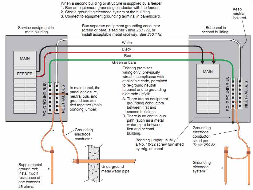
FIG. 34 Grounding at a second building or structure, 250.32.
Supplemental ground rod; install two if resistance of one exceeds 25 ohms.
Service equipment in main building; Subpanel in second building; Underground metal water pipe;
When a second building or structure is supplied by a feeder:
1. Run an equipment grounding conductor with the feeder,
2. Create grounding electrode system at the building,
3. Connect to equipment grounding terminal in panelboard.
Existing premises wiring only, previously wired in compliance with applicable code, permitted to re-ground neutral to panel and to grounding electrode only if: A. There are no equipment grounding conductors between first and second buildings.
B. There is no continuous path (such as a metal water pipe) between first and second building.
In main panel, the panel enclosure, neutral bus, and ground bus are tied together (main bonding jumper).
Run separate equipment grounding conductor (green or bare) sized per Table 250.122, or install acceptable metal raceway. See 250.118.
White Black Red Green or bare Keep neutral isolated.
Grounding electrode system
Grounding electrode conductor sized per Table 250.66 Grounding electrode conductor Bonding jumper usually a No. 10-32 screw furnished by mfg. of panel
====
Prev. | Next
Similar Articles