AMAZON multi-meters discounts AMAZON oscilloscope discounts
<< cont. from part 1
Clearing Ground Faults
Clearing a ground fault or short circuit is important because arcing damage to electrical equipment as well as conductor insulation damage is closely related to a value called ampere-squared-seconds (I^2 t), where I = the current in amperes flowing phase to ground, or phase to phase.
t = the time in seconds that the current is flowing.
Thus, there will be less equipment and/or conductor damage when the fault current is kept to a low value and when the time that the fault current is allowed to flow is kept to a minimum. The impedance of the circuit determines the amount of fault current that will flow. The speed of operation of a fuse or circuit breaker determines the amount of time the fault current will flow.
Grounding electrode conductors and equipment grounding conductors carry an insignificant amount of current under normal conditions. However, when a ground fault occurs, the equipment grounding conductor as well as the ungrounded ("hot") circuit conductors must be capable of carrying whatever value of fault current might flow (how much?) for the time (how long?) it takes for the overcurrent protective device to clear the fault and reduce the fault current to zero.
This potential hazard is recognized in the Note below Table 250.122, which states that Where necessary to comply with 250.4(A)(5) or 250.4(B)(4), the equipment grounding conductor shall be sized larger than given this table. This note calls attention to the fact that equipment grounding conductors may have to be sized larger than indicated in the table when high-level ground-fault currents are possible.
What is a high-level ground fault? To determine the available short-circuit and ground-fault current, a short-circuit calculation is necessary. It is also necessary to know the time/current characteristic of the overcurrent protective device. This is discussed in Electrical Wiring-Commercial.
This is referred to as the conductor's "withstand rating." Table 250.66 and Table 250.122 are based on the fact that copper conductors and their bolted connections can withstand
• one ampere
• for 5 seconds
• for every 30 circular mils.
Thermoplastic insulation on a copper conductor rated 75°C can safely withstand
• one ampere
• for 5 seconds
• for every 42.25 circular mils.
To exceed these values will result in damage to the conductors, with possible burn-off and loss of the grounding or bonding path.
When bare equipment grounding conductors are in the same raceway or cable as insulated conductors, always apply the insulated conductor withstand rating limitation.
Properly selected fuses and circuit breakers for normal residential installations generally will protect conductors and other electrical equipment against the types of ground faults and short circuits to be expected in homes. Fault currents can be quite high in single family homes where the pad-mounted transformer is located close to the service equipment, and in multi family dwellings (apartments, condos, town houses), making it necessary to take equipment short-circuit ratings and conductor withstand rating into consideration.
The subject of conductor and equipment with stand rating is covered in greater depth in Electrical Wiring-Commercial.
Grounding Electrode System
Article 250, Part III, covers the requirements for establishing a grounding electrode system.
NEC 250.50 requires that metal underground water piping, the metal frame of a building, a concrete encased electrode, a ground ring, and rod-pipe-plate electrodes be bonded together to create a grounding electrode system if any or all of the grounding electrodes are present in a new installation.
Metal gas piping shall never be used as a grounding electrode, 250.52(B)(1). Past experience has shown that because of galvanic action, gas pipes have deteriorated, resulting in serious incidents.
However, metal gas piping is required to be bonded.
Normally, the equipment grounding conductor for the branch circuit supplying a gas furnace serves as the required bond. NEC 250.104(B) covers the rules for bonding metal gas piping.
Should any one of these become disconnected, the integrity of the grounding system is maintained through the other paths. Here are a few key points:
• 250.90 states that bonding shall be provided where necessary to ensure electrical continuity and the capacity to conduct safely any fault cur rent likely to be imposed.*
• 250.92(A) explains what parts of a service must be bonded together.
• 250.94 explains what is acceptable as a bonding means.
• 250.96(A) states in part that bonding of metal raceways, cable armor, enclosures, frames, fit tings, and so on, that serve as the grounding path shall be effectively bonded where necessary to ensure electrical continuity and the capacity to conduct safely any fault current likely to be imposed on them.* By having all metal parts bonded together for a grounding electrode system, potential differences between non-current-carrying metal parts is virtually eliminated. In addition, the grounding electrode system serves as a means to bleed off lightning, stabilize the system voltage, and ensure that the overcurrent protective devices will operate.
========
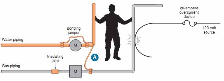
FIG. 35 Proper bonding of gas piping system eliminates shock hazard.
========
Hazard of Improper Bonding
FIG. 35 and the following steps illustrate what can happen if the electrical system is not properly grounded and bonded:
1. A "live" wire contacts the gas pipe. The bond ing jumper "A" has not been installed.
2. The gas pipe now has 120 volts on it. The pipe is energized. It is "hot."
3. The insulating joint in the gas pipe at the gas meter results in no current flow as the circuit is open.
4. The 20-ampere overcurrent device does not open, but the gas pipe remains energized.
5. If a person touches the "live" gas pipe and the water pipe at the same time, current flows through the person's body. If the hand-to-hand body resistance is 1100 ohms, the current is:
I = E/ R= 120/1,100= 0.11 amperes
This amount of current passing through a human body can cause death. See Section 6 for a discussion regarding electric shock.
6. The overcurrent device does not open.
7. If the bonding jumper "A" had been installed, it would have kept the voltage difference between the water pipe and the gas pipe at or near zero. The overcurrent device would have opened. Checking Table 8, Section 9, NEC, we find the dc resistance of 1000 feet (305 m)
of an uncoated 4 AWG copper wire is 0.308 ohms. The resistance of 100 ft (30 m) is 0.0308 ohms. The resistance of 10 ft (3.0 m) is 0.00308 ohms. The current would be:
I = E/ R =120/0.00308 =38,961 amperes
In an actual installation, the total impedance of all parts of the circuit would perhaps be much higher than these simple calculations. A lower current would result. The value of current would be enough to cause the overcurrent device to open.
Where to Connect the Grounding Electrode Conductor--NEC 250.24(A) tells us that the grounding electrode conductor shall be connected to the grounded (neutral) service conductor. See FIG. 26.
NEC 250.24(A)(1) goes on to tell us that the connection is permitted to be made at any accessible point from the load end of the service drop or service lateral up to, and including, the terminal or bus to which the grounded (neutral) service conductor is connected at the service disconnecting means.
All residential panelboards have:
• a neutral bus for the white grounded circuit conductors, and
• an equipment grounding bus for the bare equipment grounding conductors when nonmetallic sheathed cable is used as the wiring method.
The neutral conductors and equipment grounding conductors are often connected to the same terminal bar in the service equipment as permitted by NEC 408.40. Only the equipment grounding conductors are connected to the equipment grounding conductor terminal bar in subpanels.
For just about all residential services, the connection of the grounding electrode conductor is made to the neutral bus. NEC 250.24(A)(1). Many residential panelboards have a green hexagon shaped No.10-32 screw that becomes the main bonding jumper between the neutral bus and the enclosure when properly installed.
FIGs. 16, 20 and 29 through 34 show the grounding electrode conductor connected to the neutral bus in the main service panelboard.
Grounding and Bonding the Electrical System in a Typical Residence
A metal underground water piping system 10 ft (3.0 m) or longer, in direct contact with the earth, is acceptable as a grounding electrode, 250.52(A) (1). The connection of the grounding electrode conductor must be made on the first 5 ft (1.52 m) of where the metal underground water piping enters the building, 250.68(C)(1).
When metal underground water piping is used as the only grounding electrode, it must be supplemented by at least one additional grounding electrode, 250.53(D)(2). In this residence, the concrete-encased electrode and a driven ground rod are all connected together to create the grounding electrode system and automatically satisfy the requirement for the supplemental grounding electrode, as permitted by NEC 250.50 and 250.52(A)(5).
As shown in FIG. 26, the 20 ft (6.0 m) length of steel reinforcing bar that is encased in 2 in. (50 mm) of concrete near the bottom of the foundation footing is recognized in NEC 250.52(A) (3) as a grounding electrode. A 4 AWG bare copper conductor at least 20 ft (6.0 m) long installed identically to the steel reinforcing rod is also permitted as a concrete-encased grounding electrode. This is often referred to as a UFER ground, named after Herbert G. Ufer, who worked for Underwriters Laboratories. Connecting the grounding electrode conductor to a concrete-encased electrode (a mini mum 4 AWG bare copper conductor or reinforcing bars (rebars) are required by 250.66(B). A concrete encased electrode does not require a supplemental electrode as does underground metal water piping, 250.53(D)(2).
A concrete-encased electrode could also be installed vertically in a foundation wall. The key is that the foundation wall be in direct contact with the earth, 250.52(A)(3).
Watch out when using ground rods, pipes, or plates as grounding electrodes! NEC 250.53(A)(2) states that two rods, pipes, or plates be installed unless it can be shown that a single grounding electrode has a resistance to ground of 25 ohms or less.
There are a number of manufacturers of testers for measuring ground-earth resistance.
What's So Good about a Concrete-Encased Electrode? Unquestioned reliability!
The increasing use of nonmetallic water mains brought about the need to use concrete-encased electrodes. In addition, a concrete-encased electrode is recognized as a grounding electrode that provides a good connection to the earth.
When used as a grounding electrode, a concrete-encased electrode does not have to be supplemented as does a metal underground water piping system. There is no need to check for the maximum 25-ohm requirement as there is for ground rods. Many communities have mandated using a concrete-encased electrode as the primary electric service electrode because of its proven performance record of providing an excellent connection to earth.
The permanent moisture under a concrete foundation or footing ensures a low-impedance direct connection to earth. When using a concrete-encased grounding electrode, be sure that the footing or foundation is in direct contact with the earth. Make sure that there is no vapor barrier underneath the footing or foundation.
The electrician must work closely with the concrete and rebar contractor. It is necessary to bring one end (stub-up) of a reinforcing bar (called "rebar") or the bare 4 AWG copper conductor upward out of the concrete slab or footing at a location near the likely location of the electrical main service. This makes for a rather easy connection point for the grounding electrode conductor.
See 250.52(A)(3). If the rebar is brought up close to the metal water service, the bonding together of the rebar and the metal water service is easily accomplished.
If a grounding electrode conductor connection is made underground or is imbedded in concrete, the connectors must be listed for direct burial. See FIG. 26.
Coated rebars are not acceptable.
More Ground Rod Rules for Residential Application:
• The most common ground rods are copper-clad steel. Copper makes for an excellent connection between the rod and the ground clamp.
The steel gives it strength to withstand being driven into the ground. Galvanized and stain less steel rods are also available. Aluminum rods are not permitted.
• Ground rods must be at least 5/8 in. (15.87 mm) in diameter unless listed by a qualified electrical testing laboratory.
• They must be installed below the permanent moisture level if possible.
• They must not be less than 8 ft (2.5 m) in length.
• They must be driven to a depth so that at least 8 ft (2.5 m) is in contact with the soil.
• If solid rock is encountered so the rod cannot be driven vertically to the proper depth, the rod must be driven at an angle not greater than 45° from vertical.
• If the ground rod cannot be driven at an oblique angle not greater than 45° from the vertical, the rod is permitted to be installed in a trench that is at least 2 1/2 ft (750 mm) deep.
• The rod should be driven so the upper end is flush with or just below ground level. If the upper end is exposed, the ground rod, the ground clamp, and the grounding electrode conductor must be protected from physical damage.
• If more than one rod is needed, they must be kept at least 6 ft (1.8 m) apart. Driving the rods close together reduces their effectiveness because their sphere of influence overlaps.
Actually, it is better to space multiple rods twice the length of the longest rod. For example, when driving two 8-ft (2.5-m) ground rods, space them 16 ft (4.9 m) apart.
Table 3 shows accurate multipliers for multiple ground rods spaced one rod-length apart. To use this chart, divide the resistance value of one rod by the number of rods used, then apply the multiplier.
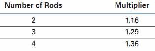
TABLE 3: Multipliers for multiple ground rods.
EXAMPLE
The ground-earth resistance reading of one 8 ft (2.5 m) ground rod is 30 ohms. This exceeds the NEC maximum of 25 ohms. A second ground rod is driven and connected in parallel to the first ground rod. What is the approximate ground- earth resistance of these two ground rods when spaced 8 ft (2.5 m) apart?
30 / 2 x 1.16 = 17.4 ohms
• A grounding electrode conductor that is the sole (only) connection to a driven ground rod need not be larger than 6 AWG copper or 4 AWG aluminum, 250.53(E), 250.66(A).
In some parts of the country, a water pipe ground is considered unreliable. The concern is the prolific use of insulating fittings and nonmetallic water piping services. These parts of the country have found that a concrete-encased electrode provides excellent grounding capabilities. Refer to 250.52(A)(3).
Other Acceptable Grounding Electrodes
• The metal frame of a building (this residence is constructed of wood), 250.50(A)(2).
• A ground ring that encircles the building consisting of not less than 20 ft (6.0 m) of bare cop per wire, minimum size 2 AWG, buried directly in the earth at least 2 1/2 ft (750 mm) deep. See 250.52(A)(4) and 250.52(G).
• Ground plates must be at least 2 ft^2 (0.186 m^2 ), 250.52(A)(7). Two ground plates are required unless the resistance of one plate is found to be 25 ohms or less, 250.53(A)(2). The ground plates must be buried at least 2 1/2 ft (750 mm) deep.
• "Other Listed Electrodes," NEC 250.52(A)(6). This "catch-all" title was added specifically to accommodate chemical ground rods. These consist of copper tubing that is filled with a natural earth salt chemical. Because they are quite expensive, it is uncommon to use them for other than commercial installations.
• 250.53(D)(2) tells us that a metal underground water piping system must have a supplemental electrode installed. Ground rods, ground plates, and underground metal water piping systems are required to have a supplemental grounding electrode. Other types of grounding electrodes, such as structural steel electrodes, concrete encased electrodes, and ground rings, do not need a supplemental electrode.
Bond All Grounding Electrodes Together
NEC 250.50 requires that if any or all of the following are present in a new installation, they must be bonded together: metal underground water pipe, metal frame of the building, concrete-encased electrode, ground ring, rod and pipe electrodes, and plate electrodes. This creates the grounding electrode system.
Some Issues Regarding Bonding of Metal Pipes Inside or Attached to the Outside of the Home
Metal water piping and metal gas piping must be properly bonded, 250.104(A) and (B).
Over the years, underground natural gas services installed from the street to the home might have been black iron pipe, copper tubing, or plastic piping designed for gas underground installations. You might even find lead water and gas pipes in homes built prior to 1963, but not likely after 1963. Today, metal gas piping installed underground has a factory applied corrosion protection coating and/or wrapping as required by NFPA 54, Natural Fuel Gas Code.
Most underground gas pipes today are plastic.
Homes have been blown off their foundations as a result of ignition and explosion of leaking gas from underground piping. The culprit causing the leak usually can be traced to corrosion. Where gas is found to be leaking from an underground copper pipe, the gas company workers pull the copper pipe out of the ground, pulling in its place an approved plastic pipe. A 14 AWG yellow tracer wire is pulled in (buried) with the plastic pipe so as to be able to locate the underground nonmetallic piping at some later date.
Underground gas line piping is not a major concern for electricians! What is of concern to the electrician is that the metal water and gas piping within or on the home must be bonded together.
Here are the NEC requirements that deal with bonding metal water and gas piping:
• 250.52(B)(1): Metal underground gas piping is not permitted to be used as a grounding electrode.
Similarly, the National Fuel Gas Code, NFPA 54, Section 7.13.3 states that Gas piping shall not be used as a grounding conductor or electrode.
To prevent galvanic corrosion of under ground metal gas piping, gas utilities install dielectric (insulating) fittings at the line side port of the gas meter. A dielectric fitting "isolates" the underground metal gas piping from the interior metal piping and prevents the corrosion problem. Today, gas companies generally install plastic piping underground. This solves the corrosion problem present when metal piping is installed underground.
• 250.104(A): Requires that interior metal water piping be bonded, and that the bonding conductor be sized according to Table 250.66.
FIG. 28 clearly shows this bond.
To control galvanic corrosion of the water heater tank and any directly connected steel, galvanized, and/or copper piping, you will usually find dielectric fittings (unions) in the water heater's cold and hot water lines. Always install the bonding jumper above the dielectric fittings.
• 250.104(B): All metal piping, including gas piping, shall be bonded. FIG. 28 clearly shows this bond.
• 250.104(B): The bonding conductor for metal gas piping shall be sized according to Table 250.122 for the ampere rating of the circuit that might energize the metal piping.
Similarly, the National Fuel Gas Code, NFPA 54, in Section 7.13.1 requires that "Each above ground portion of gas piping other than Corrugated Stainless Steel Tubing (CSST) that is likely to become energized shall be electrically continuous and bonded to an effective ground fault current path. Gas piping, other than CSST, shall be considered to be bonded when it is connected to gas utilization equipment that is connected to the appliance grounding conductor of the circuit supplying the appliance."*
In NFPA 54 7.13.2, CSST gas piping systems shall be bonded to the electrical service grounding electrode system at the point where the gas service enters the building. The bonding jumper shall not be smaller than 6 AWG copper wire or equivalent.
The logic to this requirement is that if the "hot" conductor of the electrical circuit sup plying a gas utilization equipment such as a gas furnace comes in contact with the metal frame of the appliance, the ground-fault cur rent path through the equipment grounding conductor will cause the branch-circuit overcurrent device to clear the fault. In the meantime, bonding maintains an equal voltage potential between the metal frame of the gas appliance and its metal gas supply piping. Equal voltage potential is also maintained between the faulted appliance and other nearby equipment.
If there is no likelihood of the gas pipe becoming energized (no gas appliance that is also served by electricity), then no bonding of the gas piping is required.
• 250.104(B), Informational Note: "Bonding all piping and metal air ducts within the premises will provide additional safety." Informational Notes are not mandatory but certainly provide excellent recommendations to improve safety.
In a typical home, there is usually a large number of bonds between the hot and cold water pipes.
There are interconnections at metallic mixer faucets, water heaters, clothes washers, and similar plumbing connections. Many plumbers use short lengths of copper tubing to bridge a stud space or joist space to support and keep water lines in place.
They solder (tack) the water lines to these cross pieces. This bonds the hot and cold water pipes in a number of places inside the walls.
FIG. 28 illustrates the bonding together of the cold and hot water metal pipes and the metal gas piping. This bonding jumper is sized per Table 250.66. This installation is easy and eliminates the questionable bonding/grounding of the many interconnections of the metal water and gas piping through various removable gas appliances.
This bonding above the water heater does not mean that the gas pipe is serving as a grounding electrode.
Some electrical inspectors will consider the hot/ cold mixing faucets and the water heater as an accept able means of bonding the hot and cold water metal pipes together. Most, however, will require a bonding jumper as illustrated in the figures, consistent with the thinking that electrical grounding and bonding shall not be dependent on the plumbing trade.
Don't depend on the plumber to do your job! Do it right! Follow FIG. 28 for reliably bonding together all metal water piping and metal gas piping.
The ground-fault current return path in FIG. 36 is the EMT. Where nonmetallic-sheathed cable is used, the equipment grounding conductor in the cable serves as the ground-fault current return path. Where armored cable is used, the armor plus the bonding strip is the ground-fault current return path. See NEC 250.118 for other accepted equipment grounding conductors.
NEC 300.6 addresses corrosion that an electrician needs to be concerned with when working in wet locations, underground, in concrete, and similar installations.
====
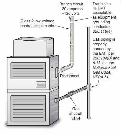
FIG. 36 Gas piping is considered to be properly bonded by
the appliance's branch-circuit equipment grounding conductor. The equipment
grounding conductor in this illustration is the EMT, which provides an excellent
ground-fault current return path.
====
Ground Clamps
Ground clamps used for bonding and grounding must be listed for the purpose. The use of sol der to make up bonding and grounding connections is not acceptable because under high levels of fault current, the solder would probably melt, resulting in loss of the integrity of the bonding and/or grounding path. See 250.8.
Various types of ground clamps are shown in FIGs. 22, 23, 24, and 25. These clamps and their attachment to the grounding electrode must conform to 250.70.
Connection of Equipment Grounding and Grounded Conductors in Main Panel and Subpanel
According to the second paragraph of 408.20, equipment grounding conductors (the bare copper equipment grounding conductors found in nonmetallic sheathed cable) shall not be connected to the grounded conductor (the neutral conductor) terminal bar (neutral bar) unless the bar is identified for the purpose, and is located where the grounded conductor is connected to the grounding electrode conductor. In this residence, this occurs in Main Panel A. The green main bonding jumper screw furnished with Panel A is installed in Panel A. This bonds the neutral bar, the ground bus, the grounded neutral conductor, the grounding electrode conductor, and the panel enclosure together, as in FIG. 16.
Grounding conductors and grounded conductors are not to be connected together anywhere on the load side of the main service disconnect, 250.24(5) and 250.142(B). The green bonding screw furnished with Panel B will not be installed in Panel B. More on this a little later in this section.
====
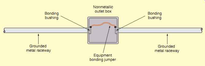
FIG. 37 Bonding jumper (equipment).
Equipment bonding jumper Grounded metal raceway Bonding bushing Bonding bushing Grounded metal raceway Nonmetallic outlet box
====
Sheet Metal Screws Not Permitted for Connecting Grounding Conductors
Sheet metal screws shall not be used to connect grounding conductors or connection devices to enclosures, 250.8. Sheet metal screws do not have the same fine thread that No. 10-32 machine screws have, which match the tapped No. 10-32 threaded holes in outlet boxes, device boxes, and other enclosures. Sheet metal screws "force" themselves into a hole instead of nicely threading themselves into a pre-tapped matching hole. Sheet metal screws have not been tested for their ability to safely carry ground-fault currents as required by 250.4(A)(5).
A typical bonding jumper (equipment) is illustrated in FIG. 37.
Bonding Service Equipment
At the main service-entrance equipment, the grounded neutral conductor must be bonded to the metal enclosure. For most residential panels, this main bonding jumper is a bonding screw that is furnished with the panel. This bonding screw is inserted through the neutral bar into a threaded hole in the back of the panel. This bonding screw must be green and must be clearly visible after it is in place, 250.28(B).
The required main bonding jumpers for services must not be smaller than the grounding electrode conductor, 250.28(D). The lugs on bonding bushings are based on the ampacity of the conductors that would normally be installed in that particular size of raceway. The lugs become larger as the trade size of the bushing increases. However, there is no need to calculate the adequacy of the device furnished by the panelboard manufacturer that is intended to function as the main bonding jumper so long as the panelboard is listed by a qualified electrical testing laboratory such as UL.
Bonding at service-entrance equipment is very important because service-entrance conductors do not have overcurrent protection at their line side, other than the electric utility company's primary transformer fuses. Overload protection for service entrance conductors is at their load end. High avail able fault currents can result in severe arcing, which is a fire hazard. For all practical purposes, available short-circuit current is limited only by (1) the kVA rating and impedance of the transformer that sup plies the service equipment, and (2) the size, type, and length of the service conductors between the transformer and service equipment. Fault currents can easily reach 20,000 amperes or more at the main service in residential installations. Much higher fault current is available in multifamily dwellings such as apartments and condominiums.
Fault current calculations are presented later in this section. The text Electrical Wiring- Commercial covers fault current calculations in greater depth.
NEC 250.92(A) and (B) lists the parts of the service-entrance equipment that must be bonded.
These include the meter base, service raceways, ser vice cable armor, and main disconnect. NEC 250.94 lists the methods acceptable for bonding all of the previous equipment.
Grounding/Bonding Bushings
Grounding bushings have a means (lug) for connecting a grounding or bonding conductor to it. A grounding bushing might also have a means (one or more set screws) that ensure reliable bonding of the bushing to a metal raceway, in which case the bushing serves as a grounding and bonding bushing. These bushings are available with an insulated throat. See FIG. 38. These are the most commonly used for bonding residential electrical services.
Bonding Bushings, Bonding Locknuts, Bonding Wedges
Bonding bushings, bonding locknuts, and bonding wedges have one or more set screws that "dig in" and secure the bushing to the electrical equipment enclosure. These products do not have a means for connecting a grounding or bonding conductor.
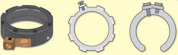
FIG. 38 An insulating grounding/bonding bushing with grounding lug, a
bonding locknut, and a bonding wedge.
Why Are Grounding/Bonding/ Insulating Bushings Installed?
Grounding/bonding bushings, bonding wedges, grounding conductors, and bonding jumpers are installed to ensure a low-impedance path if a fault occurs. Bonding jumpers are required where there are concentric or eccentric knockouts, or where reducing washers are installed. NEC 300.4(F) states that if 4 AWG or larger ungrounded circuit conductors enter a cabinet, box enclosure or raceway, an insulating bushing or equivalent must be used, shown in FIGs. 38, 39, and 40. Similar insulating bushing requirements are found in 312.6(C), 314.17(D), 314.28(A), 354.46, and 362.46. Insulating bushings protect the conductors from abrasion where they pass through the bushing. Combination metal/insulating bushings can be used. Some EMT connectors have an insulated throat. Insulating sleeves are also avail able that slide into a bushing between the conductors and the throat of the bushing.
If the bushing is made of insulating material only, as in FIG. 39, then two locknuts must be used, as shown in FIG. 40.
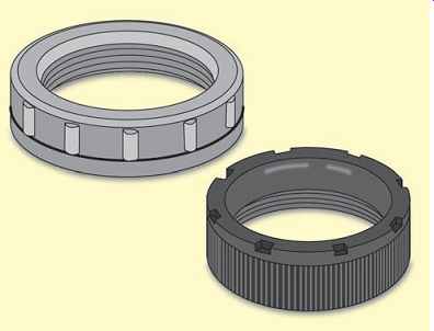
FIG. 39 Insulating bushings.
====
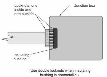
FIG. 40 The use of double locknuts plus an insulating bushing. See 300.4(F)
and 312.6(C).
Locknuts, one inside and one outside Junction box Insulating bushing (Use double locknuts when insulating bushing is nonmetallic.)
====
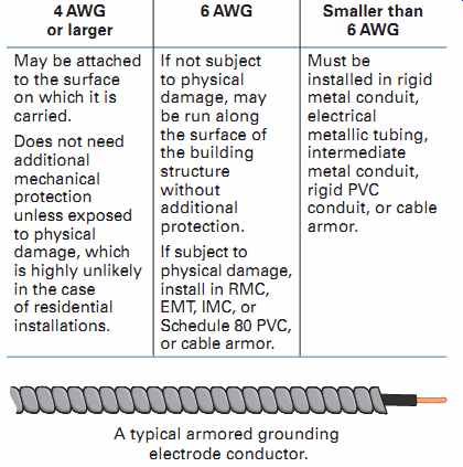
TABLE 4 Installing a grounding electrode conductor.
4 AWG or larger 6 AWG Smaller than 6 AWG May be attached to the surface on which it is carried.
Does not need additional mechanical protection unless exposed to physical damage, which is highly unlikely in the case of residential installations.
If not subject to physical damage, may be run along the surface of the building structure without additional protection.
If subject to physical damage, install in RMC, EMT, IMC, or Schedule 80 PVC, or cable armor.
Must be installed in rigid metal conduit, electrical metallic tubing, intermediate metal conduit, rigid PVC conduit, or cable armor.
A typical armored grounding electrode conductor.
===
Installing a Grounding Electrode Conductor from Main Service Disconnect to Metal Underground Water Pipe that Will Serve as the Grounding Electrode
The Code specifies in NEC 250.64 how a grounding electrode conductor is to be installed, as shown in Table 4.
In order to carry high values of ground-fault current, the ground-fault current path must have as low an impedance as possible. This means that the path must be continuous, must have the capability of carrying any value of fault current that it might be called on to carry, and shall have an impedance low enough to limit the voltage to ground and to ensure that the protective overcurrent device will operate.
NEC 250.90 and 250.96 have similar requirements.
For example, the metal raceway enclosing a grounding electrode conductor must be continuous from the main disconnect to the ground clamp, or be made continuous by proper bonding.
NEC 250.64(E) requires that the metal race way that encloses a grounding electrode conductor be bonded to the conductor at both ends. At first thought, it might appear that simply installing a grounding electrode conductor in a metal raceway makes for a neat and workmanlike installation.
However, unless the enclosing metal raceway is properly bonded on both ends, the ground path will be a high-impedance path. Bonding the enclosing metal raceway at one end only will result in a ground path impedance approximately twice that of bonding the metal raceway on both ends. Remember- the higher the impedance, the lower the current flow.
A TYPICAL ARMORED GROUNDING ELECTRODE CONDUCTOR
Past testing has shown that under certain conditions for a 300-ampere ground fault, approximately 295 amperes flowed in the metal raceway, and 5 amperes flowed in the enclosed grounding electrode conductor. Another test revealed that for a 590-ampere ground fault, 585 amperes flowed in the metal raceway, and 5 amperes flowed in the enclosed grounding electrode conductor. These tests showed that under the conditions of the test, the conduit provided a lower impedance path than the contained conductor. Proper bonding at both ends of a metal raceway is necessary to ensure a low impedance path that will safely transfer the high magnitudes of ground-fault current flowing in the metal conduit to the ground bus in the main panel, and/or to the ground clamp.
FIGs. 29, 30, 31, 32, and 33 illustrate accepted methods of installing a grounding electrode conductor between the main panel and the ground clamp. Additional information concerning grounding electrode conductors can be found in Section 4.
GROUNDING ELECTRICAL EQUIPMENT AT A SECOND BUILDING
Detached Garage-Grounding A detached garage or other second building on the same residential property is almost always served by the same electrical service as the house.
For dwellings, a detached garage is not required to have any electrical supply. However, if you do run electric power to a detached garage, specific Code requirements must be complied with.
We discussed the receptacle and lighting requirements for garages in Section 3. We will now discuss the grounding requirements for a second building, 250.32. See FIG. 34.
Branch Circuit to Detached Garage
If a single or multiwire branch circuit is run to a detached garage or other second building, the simplest way to provide proper and adequate grounding for the equipment in that detached garage is to install an underground cable Type UF that contains an equipment grounding conductor. A grounded metal race way between the house and the outbuilding may also serve as the equipment grounding conductor.
A separate grounding electrode at the second building is not required if only a single branch circuit supplies the building, 250.32(A), Exception.
Feeder to Detached Garage
When a feeder supplies a panel in a detached garage or other second building that has more than one branch circuit, proper grounding at the second building is accomplished by:
• installing a metal raceway, which is an accept able equipment grounding conductor in NEC 250.118, between the main building panel and the panel in the second building, or
• installing a separate equipment grounding conductor of the wire type (in a cable or in a nonmetallic raceway) between the main building panel and the panel in the second building.
In either case, a grounding electrode system is required at the second building. A grounding electrode conductor is run between the grounding electrode and the equipment grounding bus in the panelboard in the second building.
The grounding electrode conductor is sized according to Table 250.66, but it does not have to be larger than the largest ungrounded supply conductor, 250.32(E).
The neutral bus and the equipment grounding bus in the second building are not connected together. If these two buses were tied together in the second building, there would be more than one path (a parallel path) for neutral current to flow back on. Take a look at FIG. 34. Imagine a tie between the neutral bus and the equipment grounding bus in the second building. Now imagine that there is some value of neutral current.
You can readily see that this neutral current would have many ways to return to the source at the main building panel. Some current would return on the neutral conductor, some on the equipment grounding conductor, some on the grounding electrode conductor-to the grounding electrode-and back through the earth, and some through a metal water pipe if one is present. These multiple paths of neutral return current are not permitted.
All of the above requirements are found in 230.32, and are illustrated in FIG. 33.
REVIEW
Note: Refer to the NEC, the text, and/or the plans where necessary.
1. Define the Service Point.
2. Define service-drop conductors.
3. Who is responsible for determining the service location?
4. a. The service head must be located (above) (below) the point where the service drop conductors are spliced to the service-entrance conductors. (Circle the correct answer.)
b. What Code section provides the answer to part (a)?
5. What is a mast-type service entrance?
6. When a conduit is extended through a roof, must it be guyed?
7. a. What size and type of conductors are installed for this service?
b. What size conduit is installed?
c. What size grounding electrode conductor is installed? (not neutral)
d. Is the grounding electrode conductor insulated, armored, or bare?
8. How and where is the grounding electrode conductor attached to the water pipe?
9. What are the minimum distances or clearances for the following?
a. Overhead service conductor clearance over private driveway
b. Overhead service conductor clearance over private sidewalks
c. Overhead service conductor clearance over alleys
d. Overhead service conductor clearance over a roof having a roof pitch of not less than 4/12. (Voltage between conductors does not exceed 300 volts.)
e. Overhead service conductor horizontal clearance from a porch
f. Overhead service conductor clearance from a fence that can be climbed on
10. What are the minimum size ungrounded conductors using Type THW copper for the following residential electrical services? The terminals in the panelboard are marked 75°C. Ampere Rating Service-Entrance Conductors Service-Entrance Conductors of Service Sized per Table 310.15(B)(16) Sized per Table 310.15(B)(7)
100
200
400
11. What is the minimum size copper grounding electrode conductor for each of the following residential electrical services? Refer to Table 250.66. The ungrounded conductors are Type THW copper.
Grounding Electrode Conductor Grounding Electrode Conductor
When the Service-Entrance When the Service-Entrance Ampere Rating Conductors Are Sized per Conductors Are Sized per of Service Table 310.15(B)(16) Table 310.15(B)(7)
100
200
400
* Table 310.15(B)(7) is only for 120/240-volt, single-phase residential services and feeders. This table does not apply to services and feeders other than residential.
12. What is the recommended height of a meter socket from the ground?
13. a. May the bare grounded neutral conductor of a service be buried directly in the ground?
b. What section of the Code covers this?
14. How far must mechanical protection be provided when underground service conductors are carried up a pole?
15. a. A service disconnect may consist of not more than how many switches or circuit breakers?
b. Must these devices be in one enclosure?
c. What type of main disconnect is provided in this residence?
d. Does your city permit more than one service disconnect?
16. Complete the following table by filling in the columns with the appropriate information.
Circuit Ampere Conductor
Number Rating Poles Volts Size A. Living room receptacle outlets B. Workbench receptacle outlets C. Water pump D. Attic exhaust fan E. Kitchen lighting F. Hydromassage tub G. Attic lighting H. Counter-mounted cooking unit I. Electric furnace
17. a. What size conductors supply Panel B?
b. What size raceway?
c. Is this raceway run in the form of electrical metallic tubing or rigid conduit?
d. What size overcurrent device protects the feeders to Panel B?
18. How many electric meters are provided for this residence?
19. a. According to the NEC, is it permissible to ground a residential rural electrical service to driven ground rods only when a metallic water system is available?
b. What sections of the Code apply?
20. What table in the NEC lists the sizes of grounding electrode conductors required for electrical services of various sizes? Table 21. NEC 250.53(D)(2) requires that a supplemental ground be provided if the available grounding electrode is: (Circle the correct answer.)
a. metal underground water pipe.
b. building steel.
c. concrete encased ground.
22. Do the following conductors require mechanical protection?
a. 8 AWG grounding electrode conductor
b. 6 AWG grounding electrode conductor
c. 4 AWG grounding electrode conductor
23. Why is bonding of service-entrance equipment necessary?
24. What special types of bushings are required on service entrances?
25. When insulated conductors 4 AWG or larger that are required to be insulated are installed in conduit, what additional provision is required on the conduit ends?
26. What minimum size copper bonding jumpers must be installed to bond properly the electrical service for the residence discussed in this text?
27. a. Where is Panel A located?
b. On what type of wall is Panel A fastened?
c. Where is Panel B located?
d. On what type of wall is Panel B fastened?
28. When conduits pass through the wall from outside to inside, the conduit must be to prevent air circulation through the conduit.
29. Briefly explain why electrical systems and equipment are grounded.
30. In general, systems are required to be grounded if the maximum voltage to ground does not exceed: (Circle the correct response.)
a. 120 volts.
b. 150 volts.
c. 300 volts.
31. To ensure a complete grounding electrode system: (Circle the correct response.)
a. everything must be bonded together.
b. all metal pipes and conduits must be isolated from one another.
c. the service neutral is grounded to the water pipe only.
32. An electric clothes dryer is rated at 5700 watts. The electric rate is 10.091 cents per kilowatt-hour. The dryer is used continuously for 3 hours. Find the cost of operation, assuming the heating element is on continuously. $
33. A heating cable rated at 750 watts is used continuously for 72 hours to prevent snow from freezing in the gutters of the house. The electric rate is 8.907 cents per kilowatt hour. Find the cost of operation. $
34. When used as service equipment, a panelboard (load center) must be ____ that is suitable for use as service equipment, 230.66. If the panelboard (load center)
contains the main service disconnect, it must be clearly marked __, 230.70(B).
35. Here are five commonly used terms in the electrical industry. Enter the letter of the term that corresponds to its definition.
a. Grounding electrode conductor
b. Main bonding jumper
c. Grounded circuit conductor
d. Equipment grounding conductor
e. Underground service conductors (Service Point at transformer)
______ The neutral conductor.
______ The term used to define underground service-entrance conductors that run between the meter and the utilities connection.
______ The conductor (sometimes a large threaded screw) that connects the neutral bar in the service equipment to the service-entrance enclosure.
______ The conductor that runs between the neutral bar in the main service equipment to the grounding electrode (water pipe, ground rod, etc.).
______ The bare copper conductor found in nonmetallic-sheathed cable.
36. The electrician mounted the disconnect switch for a central air-conditioning unit 8 ft (2.5 m) above the ground. This was easy to do because all he had to do was run the conduit across the ceiling joists in the basement, through the outside wall, and directly into the back of the disconnect switch. The electrical inspector turned the job down, citing NEC ________ that requires that the disconnecting operating handle must not be higher than ______ feet above the ground.
37. a. According to the NEC definition of a wet location, a basement cement wall that is in direct contact with the earth is considered to be a wet location. A panelboard mounted on this wall must have at least [¼ in. (6 mm)], [½ in. (13 mm)] [1 in. (25 mm)] space between the wall and the panel. Circle the correct answer. b. How is this required spacing accomplished?
38. When using rebars as the concrete-encased electrode, the rebars must be (a) insulated with plastic material so they will not rust, or (b) bonded together by the usual steel tie wires or other effective means. Underline the correct answer.
39. The circuit directory in a panelboard (may) (shall) be filled out according to NEC _. Circle the correct answer, and enter the correct NEC section number.
40. A main service panel is located in a dark corner of a basement, far from the basement light. In your opinion, does this installation meet the requirements of 110.26(D)? Explain your answer.
41. Does the electric utility in your area allow the location of the meter to be on the back side of a residence?
42. The term used when the utility charges different rates during different periods during the day is .
43. A ground rod is driven below the meter outside of the house. A grounding electrode conductor connects between the meter base and the ground rod. The ground clamp is buried under the surface of the soil. This is permitted if the ground clamp is ___ for direct burial according to NEC ___.
44. Copper-coated steel ground rods are the most commonly used grounding electrodes.
These rods shall:
a. be at least _____ in. (_____ mm) in diameter, 250.52(A)(5).
b. be driven to a depth of at least ________ ft (________ m) unless solid rock is encountered, in which case the rod may be driven at a ________-° angle, or it may be laid in a trench that is at least _____ft (____ mm) deep, 250.53(G).
c. be separated by at least ________ ft (________ m) when more than one rod is driven, 250.53(A)(3).
d. have a ground resistance of not over ______ ohms for one rod, 250.53(A)(2) Exception.
45. What section of the Code prohibits the use of sheet metal screws as a means of attaching grounding conductors to enclosures? NEC
46. Which section of the NEC prohibits using the space below and in front of an electrical panel as storage space? NEC .
47. What section of the NEC prohibits using an underground metal gas pipe as the grounding electrode for an electrical service?
48. When wiring a gas furnace, what additional steps, if any, are necessary in order to make sure that the gas piping supplying the furnace is adequately bonded? Explain.
Prev. | Next
Similar Articles