AMAZON multi-meters discounts AMAZON oscilloscope discounts
OBJECTIVES
• install residential telephone and television wiring, antennas, and CATV cables, in conformance to NEC requirements.
• describe the basic operation of satellite antennas.
• install typical low-voltage wiring for chimes.
INSTALLING THE WIRING FOR HOME TELEVISION
This section discusses the basics of installing out lets, cables, receivers, antennas, amplifiers, multiset couplers, and some of the NEC rules for home television. Television is a highly technical and complex field. To ensure a trouble-free installation of a home system, a competent television technician should do the work. These individuals receive training and certification through the Electronic Technicians Association in much the same way that electricians receive their training through apprenticeship and journeyman training programs.
Some cities and states require that, when more than three television outlets are to be installed in a residence, the television technician making the installation be licensed and certified. Just as electricians can experience problems because of poor connections, terminations, and splices, poor reception problems can arise as a result of poor terminations.
In most cases, poor crimping is the culprit. Electrical shock hazards are present when components are improperly grounded and bonded.
According to the plans for this residence, television outlets are installed in the following rooms:
Front Bedroom 2
Kitchen 1
Laundry 1
Living Room 3
Master Bedroom 2
Recreation Room 3
Study/Bedroom 2
Workshop 1
Total: 15
Because TV is a low-voltage system, metallic or nonmetallic standard single-gang device boxes, 4-in. square outlet boxes with a plaster ring, plaster rings only, or special mounting brackets can be installed during the rough-in stage at each likely location of a television set (more on this later). See FIG. 1. For new construction, shielded coaxial cables are installed concealed in the walls. For remodel work, cables can be concealed in the walls by fishing the cables through the walls and installing mounting brackets that are inserted and snapped into place through a hole cut into the wall.
Shielded 75-ohm RG-6 coaxial cable is most often used to hook up television sets to minimize interference and keep the color signal strong.
There are different kinds of shielded coaxial cable.
Double-shielded cable that has a 100% foil shield covered with a 40% or greater woven braid is recommended. This coaxial cable has a PVC outer jacket.
The older style, flat 300-ohm twin-lead cable, can still be found on existing installations, but the reception might be poor. To improve reception, 300-ohm cables can be replaced with shielded 75-ohm coaxial cables.
===
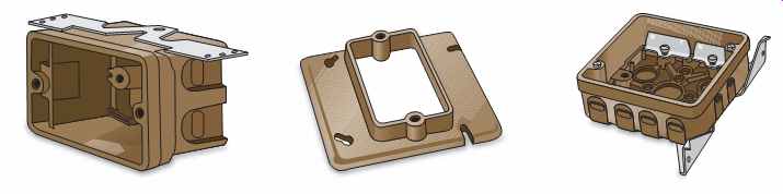
FIG. 1 Nonmetallic boxes and a nonmetallic plaster ring.
===
For this residence, 15 television outlets are to be installed. A shielded 75-ohm RG-6 coaxial cable will be run from each outlet location back to one central point, as in FIG. 2.
This central point could be where the incoming Community Antenna Television (CATV) cable comes in, where the cable from an antenna comes in, or where the TV output of a satellite receiver is carried. For rooftop or similar antenna mounting, the cable is run down the outside of the house, then into the basement, garage, or other convenient location where the proper connections are made. CATV companies generally run their incoming coaxial cables underground to some convenient point just inside of the house. Here, the technician hooks up all of the coaxial cables coming from the TV outlets to an amplifier that boosts the signal and improves reception, FIG. 2, or to a multi-set splitter, FIG. 3. An amplifier may not be necessary if only those coaxial cables that will be used are hooked up.
Cable television does not require an antenna on the house because generally the cable company has the proper antenna to receive signals from satellites.
The cable company then distributes these signals throughout the community they have contractually agreed to serve. These contracts usually require the cable company to run their coaxial cable to a point just inside the house. Inside the house, they will complete the installation by furnishing cable boxes, controls, and the necessary wiring. In geographical areas where cable television is not available, antennas, as shown in FIG. 4 and FIG. 5, are needed.
Faceplates for the TV outlets are available in styles to match most types of electrical faceplates in the home.
===
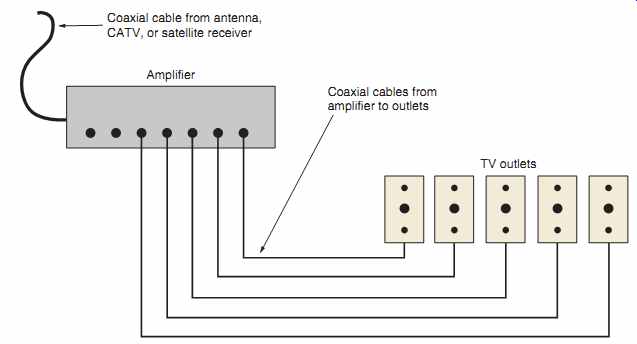
FIG. 2 A television master amplifier distribution system may be needed
where many TV outlets are to be installed. This will minimize the signal loss.
In simple installations, a multiset coupler can be used, as shown in FIG. 3.
Amplifier, TV outlets, Coaxial cable from antenna, CATV, or satellite receiver,
Coaxial cables from amplifier to outlets
===
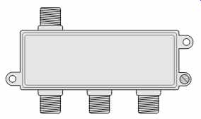
FIG. 3 A 3-way CATV cable splitter: one in, three out. Two-way and 4-way
splitters are also commonly available.
===
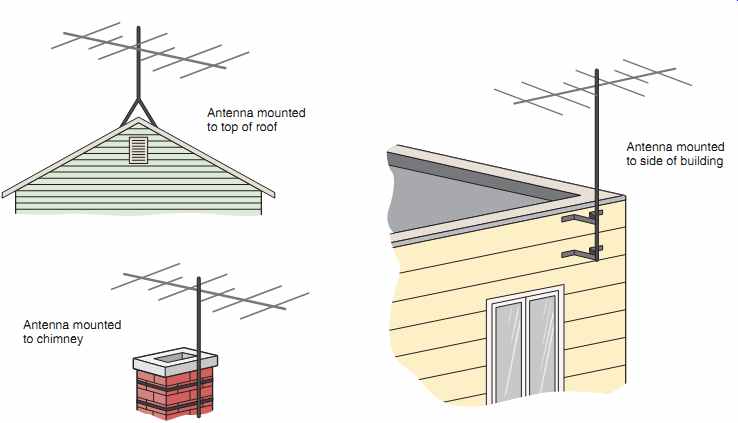
FIG. 4 Older style antennas. Although still available, they have given
way to the more popular digital satellite "dish," as shown in FIG. 5(A).
Antenna mounted to top of roof; Antenna mounted to chimney; Antenna mounted to side of building
===
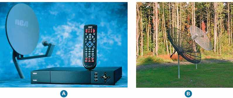
FIG. 5 (A) A digital satellite system 18-in. (450 mm) antenna, a receiver,
and a remote control. (B) A large satellite antenna securely mounted to a post
that is anchored in the ground.
These large antennas are rarely used today.
===
Hazards of Mixing Different Voltages
For safety reasons, voice/data/video (VDV) wiring must be separated from the 120-volt wiring.
If both 120-volt and low-voltage circuits are run into the same box, then a permanent barrier must be provided in the box to separate the two systems.
A better choice is to keep the two systems totally separate using two wall boxes.
Another popular choice is where VDV cables are run to a location right next to a 120-volt receptacle. Mounting brackets that are commercially available can be installed around the electrical device box during the rough-in stage. This lets you trim out a 120-volt receptacle and VDV jacks with one faceplate, as shown in FIG. 6.
These mounting brackets keep the center-to center measurements of the device mounting holes for the electrical box and the VDV wiring precisely in alignment. With this method, a wall box is not provided for the VDV wiring.
The VDV cables merely come out of the drywall next to the electrical box, and the faceplate takes care of trimming out the receptacle and the VDV wiring jacks.
When wiring a new house, it certainly makes sense to run at least one coaxial cable and one Category 5 cable to a single wall box wherever TV, telephone, and/or computers might be used.
This could be a single box located close to a 120 volt receptacle outlet, or it could be a mounting bracket as shown in FIG. 6. Run a separate coaxial cable and a separate Category 5 cable from each location to a common point in the house. You will use a lot of cable, but this will enable you to interconnect the cables as required, such as for a local area network (LAN) to serve more than one computer located in different rooms, or other home automation systems. This is the beginning of "structured wiring," as discussed in Section 31.
For adding VDV wiring to an existing home, many types of nonmetallic brackets are available that snap into a hole cut in the drywall and lock in place.
More NEC rules are discussed later in this section.
Section 31 discusses structured wiring using Category 5 unshielded twisted pair (UTP) cable and coaxial shielded cable.
Although shielded coaxial cable minimizes interference, it is good practice to keep the coaxial cables on one side of the stud space and keep the light and power cables on the other side of the stud space.
===
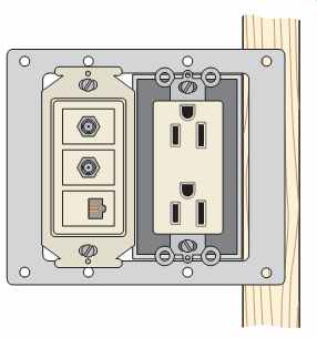
FIG. 6 A special mounting bracket fastened to the wood stud. The bracket
fits nicely over the electrical wall box to accommodate a 120-volt receptacle,
two coaxial outlets, and one telephone outlet. A single two-gang faceplate
is used for this installation.
Many other combinations are possible.
===
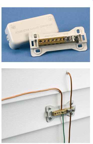
FIG. 7 Intersystem bonding termination equipment. (Courtesy of Erico)
===
Intersystem Bonding Termination
An intersystem bonding termination is required to be installed at or near the service equipment and at or near the building disconnecting means if remote buildings are supplied with electric power, FIG. 7. The intersystem bonding termination is intended to provide a convenient location where systems such as telephone, television, and antenna systems can be bonded together. This ensures that all the electrical systems that supply the building or structure are bonded (connected together). This helps reduce dangerous flashover should overvoltages be imposed on the electrical systems. These overvoltages originate from lightning events or from problems related to the electric utility system.
The intersystem bonding termination equipment is required to:
1. be accessible for connection and inspection.
2. consist of a set of terminals with the capacity for connection of not less than three intersystem bonding conductors.
3. not interfere with opening the enclosure for a service, building, or structure disconnecting means, or metering equipment.
4. at the service equipment, be securely mounted and electrically connected to an enclosure for the service equipment, to the meter enclosure, or to an exposed nonflexible metallic service raceway, or be mounted at one of these enclosures and be connected to the enclosure or to the grounding electrode conductor with a minimum 6 AWG copper conductor.
5. at the disconnecting means for a building or structure, be securely mounted and electrically connected to the metallic enclosure for the building or structure disconnecting means, or be mounted at the disconnecting means and be connected to the metallic enclosure or to the grounding electrode conductor with a mini mum 6 AWG copper conductor.
6. be listed as grounding and bonding equipment.
Code Rules for Cable Television (CATV) (Article 820)
The letters CATV stand for "Community Antenna Television," often simply referred to as "Cable TV." CATV systems are installed both overhead and underground in a community. Then, to supply an individual customer, the CATV company runs coaxial cables through the wall of a residence at some convenient point. Up to this point of entry (Article 820, Part II) and inside the building (Article 820, Part V), the cable company must conform to the requirements of Article 820, plus local codes if applicable.
Coaxial cable generally used for one- and two family dwellings is Type CATV and CATVX. The cable shall be listed. See 820.154, 820.179(C), and 820.179(D). Other types of acceptable cables are shown in Table 820.154(b).
Here are some of the key rules to follow when making a coaxial cable installation:
1. The outer conductive shield of the coaxial cables must be grounded as close to the point of entry as possible, 820.93.
2. Coaxial cables shall not be run in the same conduits or box with electric light and power conductors, 820.133(A)(1)(c).
3. Do not support coaxial cables from raceways that contain electrical light and power conductors, 820.133(B).
4. Keep the coaxial cable at least 2 in. (50 mm) from light and power conductors unless the conductors are in a raceway, nonmetallic sheathed cable, armored cable, or UF cable, 820.133(A)(2). This clearance requirement really pertains to old knob-and-tube wiring.
The 2-in. (50-mm) clearance is not required if the coaxial cable is in a raceway.
5. Where underground coaxial cables are run, they must be separated by at least 12 in. (300 mm) from underground light and power conductors, unless the underground conductors are in a raceway, Type UF cable, or Type USE cable, 820.47(B). The 12-in. (300-mm) clearance is not required if the coaxial cable has a metal cable armor.
6. The bonding and grounding conductor (Article 820, Part III and Part IV):
a. outer conductive shield shall be grounded as close as possible to the coaxial cable entrance or attachment to the building, 820.93(A).
b. shall not be smaller than a 14 AWG copper or other corrosion-resistant conductive material. It need not be larger than 6 AWG copper. The bonding or grounding electrode conductor is permitted to be insulated, covered or bare. It shall have a current-carrying capacity not less than that of the coaxial cable's outer metal shield.
See NEC 810.100(A)(1), (A)(2) and (A)(3).
c. length shall be as short as possible, but not longer than 20 ft (6.0 m). If impossible to keep the grounding conductor to this maximum permitted length, then the Exception to 820.100(A)(4) permits installing a separate grounding electrode. These two electrodes shall be bonded together with a bonding conductor not smaller than 6 AWG copper.
d. may be solid or stranded, 820.100(A)(2).
e. shall be run in a line as straight as practical, 820.100(A)(5).
f. is required to be protected against physical damage. If run in a metal raceway, the metal raceway shall be bonded to the bonding or grounding electrode conductor at both ends, 820.100(A)(6).
g. shall be connected to the nearest accessible location on one of the following, 820.100(B):
• bonded to the intersystem bonding termination if one exists, 820.100(B)(1).
• If the building or structure has no intersystem bonding means such as a terminal bar, the bonding conductor or grounding electrode conductor is to be connected to one of the following:
1. the building grounding electrode system.
2. the grounded interior metal water piping pipe, within 5 ft (1.5 m) of where the pipe enters the building.
Refer to 250.52.
3. the power service accessible means external to the enclosure.
4. the metallic power service raceway.
5. the service equipment enclosure.
6. the grounding electrode conductor or its metal enclosure.
7. the grounding electrode conductor or grounding electrode of a disconnecting means that is grounded to an electrode according to 250.32. This pertains to a second building on the same property served by a feeder or branch circuit from the main electrical service in the first building.
h. If none of the options in part (g) is available, then ground to any of the electrodes, per 250.52, such as metal underground water pipes, the metal frame of the building, a concrete encased electrode, or a ground ring. Watch out for the maximum length permitted for the bonding or grounding electrode conductor, as mentioned above.
When installing CATV wiring and equipment, do it in a neat and workmanlike manner, not subject to physical damage when run on building surfaces.
Secure cables with listed hardware, including straps, cable ties, and so on, 820.24. The requirements found in 300.4(D) (Cables and Raceways Parallel to Framing Members and Furring Strips) and 300.11 (Securing and Supporting) also apply to CATV cables.
CAUTION: DO NOT simply drive a separate ground rod to ground the metal shielding tape on the coax cable. Difference of potential between the coax cable shield and the electrical system ground during lightning strikes could result in a shock hazard as well as damage to the electronic equipment. If for any reason one grounding electrode is installed for the CATV shield grounding and another grounding electrode for the electrical sys tem, bonding these two electrodes together with no smaller than a 6 AWG copper conductor will minimize the possibility that a difference of potential voltage might exist between the two electrodes.
===
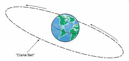
FIG. 8 All satellites travel around the Earth in the same orbit called
the "Clarke Belt." They appear to be stationary in space because
they are rotating at the same speed at which the Earth rotates. This is called "geosynchronous
orbit (geostationary orbit)." The satellite receives the uplink signal
from Earth, amplifies the signal, and transmits it back to Earth.
The downlink signal is picked up by the satellite antenna.
===
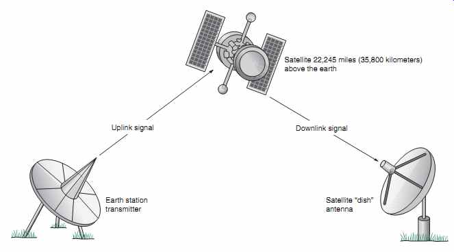
FIG. 9 The Earth station transmitter beams the signal up to the satellite,
where the signal is amplified, converted, and beamed back to Earth.
Uplink signal
Downlink signal
Earth station transmitter
Satellite ‘dish’ antenna
Satellite 22,245 miles (35,800 kilometers) above the earth
===
SATELLITE ANTENNAS
A satellite antenna is often referred to as a "dish." See FIG. 5. A satellite dish has a parabolic shape that concentrates and reflects the signal beamed down from one of the many stationary satellites orbiting 22,245 miles (35,800 kilometers) above the equator. Stationary means that the satellite is traveling at the same speed that the Earth rotates.
The orbit in which satellites travel is called the "Clarke Belt," as shown in FIG. 8.
The latest satellite technology is the digital satellite system (DSS). A digital system allows the use of small antennas, approximately 18 in. (450 mm) in diameter, which can easily be mounted on a roof, a chimney, the side of the house, a pipe, or a pedestal, using the proper mounting hardware.
Although rarely used today for residential TV reception, large dish satellite antennas of the type shown in FIG. 5(B) are still in use. Because of their huge size and weight, proper installation is important.
The basic operation of a satellite system is for a transmitter on Earth to beam an "uplink" signal to a satellite in space. Electronic devices on the satellite re-amplify and convert this signal to a "downlink" signal, then retransmit the downlink signal back to earth, as shown in FIG. 9.
Regardless of the type of antenna used, the line of sight from the antenna to the satellite must not be obstructed by trees, buildings, utility poles, or other structures. Instructions furnished with an antenna provide the necessary data for direction and up angle based on ZIP codes.
Before installing an antenna, check with your local inspection department. Local codes might have restrictions and requirements in addition to the NEC.
Figures 10 and 11 show typical connections between a television set, receiver, VCR, and antenna. The manufacturer's installation instructions are always to be followed.
FIG. 12 illustrates one method of installing a large antenna post in the ground in accordance to a manufacturer's instruction.
====
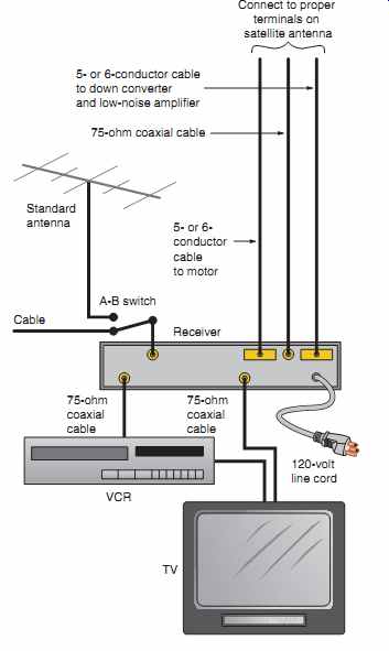
FIG. 10 Typical satellite antenna/cable/ standard antenna wiring.
Connection to a standard antenna cable, CATV cable, or to a satellite cable enables the homeowner to watch one channel while recording another channel. The installation manual for the receiver usually has a number of different hookup diagrams. In this diagram, the A-B switch allows a choice of connecting to a standard antenna or to the CATV cable. This hookup can be desirable should the CATV or satellite reception fail.
TV 75-ohm coaxial cable 120-volt line cord 75-ohm coaxial cable Standard antenna Connect to proper terminals on satellite antenna 5- or 6- conductor cable to motor Cable A-B switch VCR Receiver 5- or 6-conductor cable to down converter and low-noise amplifier 75-ohm coaxial cable
====
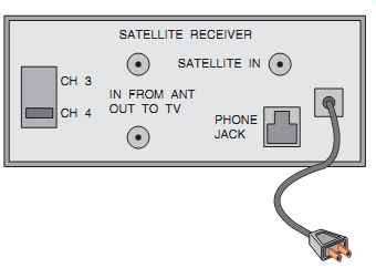
FIG. 11 The terminals on the back of a digital satellite receiver. The
connections are similar to those in FIG. 10. Note the difference in that
the digital satellite receiver has a modular telephone plug, a feature that
uses a toll free number to update the access card inside the receiver to ensure
continuous program service.
The telephone can also handle program billing.
===
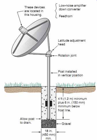
FIG. 12 Satellite antenna solidly installed in the ground according to
the manufacturer's instructions. The popularity of these large antennas has
given way to the small digital satellite system antenna, as shown in FIG. 5.
===
CODE RULES FOR THE INSTALLATION OF ANTENNAS AND LEAD-IN WIRES (ARTICLE 810)
Home television and AM and FM radios generally come complete with built-in antennas. For those locations in outlying areas on the fringe or out of reach of strong signals, it is quite common to install a separate antenna system or a satellite antenna system.
You will want to read NEC 250.94 to learn more about the requirements for intersystem bonding.
Indoor or outdoor antennas may be used with televisions. The front of an outdoor antenna is aimed at the television transmitting station. When there is more than one transmitting station and they are located in different directions, a rotor is installed.
A rotor turns the antenna on its mast so that it can face in the direction of each transmitter. The rotor is controlled from inside the building. The rotor controller's cord is plugged into a regular 120-volt receptacle to obtain power. A 3-wire or 4-conductor cable is usually installed between the rotor motor and the control unit. The wiring for a rotor may be installed during the roughing-in stage of construction, running the rotor's cable into a device wall box, allowing 5 to 6 ft (1.5 to 1.8 m) of extra cable, then installing a regular single-gang switchplate when finishing.
Article 810 covers radio and television equipment. Although instructions are supplied with antennas, the following key points of the Code regarding the installation of antennas and lead-in wires should be followed:
1. Antennas and lead-in conductors shall be securely supported, 810.12.
2. Antennas and lead-in conductors shall not be attached to the electric service mast, 810.12.
3. Antennas and lead-in conductors shall not be attached to any poles that carry light and power wires over 250 volts between conductors, 810.12.
4. Lead-in conductors shall be securely attached to the antenna, 810.12.
5. Antennas and lead-in conductors shall be kept away from all light and power conductors to avoid accidental contact with the light and power conductors, 810.13.
6. Outdoor antennas and lead-in conductors shall not cross over light and power conductors, 810.13.
7. Outdoor antennas and lead-in conductors shall be kept at least 24 in. (600 mm) away from open light and power conductors, 810.13.
8. Where practicable, antenna conductors shall not be run under open light and power conductors, 810.13.
9. On the outside of a building:
a. Position and fasten lead-in conductors so they cannot swing closer than 24 in.
(600 mm) to light and power conductors having not over 250 volts between conductors; 10 ft (3.0 m) if over 250 volts between conductors, 810.18(A).
b. Keep lead-in conductors at least 6 ft (1.8 m) away from a lightning rod system, 810.18(A), or bonded together according to 250.60.
c. Underground lead-in radio and television conductors and cables shall be separated by at least 12 in. (300 mm) from underground light and power conductors.
Note: The clearances in a, b, and c are not required if the light and power conductors or the lead-in conductors are in a metal raceway or metal cable armor.
10. On the inside of a building:
a. Keep the antenna and lead-in conductors at least 2 in. (50 mm) from other open wiring (as in old houses) unless the other wiring is in a metal raceway or cable, 810.18(B).
b. Keep lead-in conductors out of electric boxes unless there is an effective, permanently installed barrier to separate the light and power wires from the lead-in wire, 810.18(C).
11. Grounding:
a. All metal masts and metal structures that support antennas shall be grounded, 810.21.
See FIG. 12.
b. The grounding conductor must be cop per, aluminum, copper-clad steel, bronze, or a similar corrosion-resistant material, 810.21(A).
c. The bonding or grounding electrode conductor need not be insulated. It must be securely fastened in place, may be attached directly to a surface without the need for insulating supports, shall be protected from physical damage or be large enough to compensate for lack of protection, and shall be run in as straight a line as is practicable, 810.21(B), (C), (D), and (E).
d. In buildings with an intersystem bonding termination, the bonding conductor shall be connected to the intersystem bonding termination. See FIG. 13.
e. If the building or structure does not have an intersystem bonding means, the bonding conductor or grounding electrode conductor is required to be connected to the nearest accessible location on one of the following:
• the building or structure grounding electrode system. Refer to 250.50 for more details.
• the grounded interior metal water pipe, within 5 ft (1.52 m) of where the water pipe enters the building. Refer to 250.53 and 250.68(C) for more details.
• the metallic power service raceway.
• the service equipment enclosure.
• the grounding electrode conductor or the grounding electrode conductor metal enclosure of the power service.
f. If neither d nor e is available, then connect a grounding electrode conductor to any one of the grounding electrodes, per 250.52, such as metal underground water pipe, metal frame of building, concrete-encased electrode, or ground ring, 810.21(F)(3).
g. The grounding conductor may be run inside or outside of the building, 810.21(G).
h. The grounding conductor shall not be smaller than 10 AWG copper or 8 AWG aluminum, 810.21(H).
i. Protect the grounding conductor from physical damage. If run in a metal race way, the metal raceway shall be bonded to the grounding conductor at both ends, 800.21(D).
CAUTION: DO NOT simply drive a separate ground rod to ground the metal mast, structure, or antenna. Difference of potential between the metal mast, structure, or antenna and the electrical system ground during a lightning strike could result in a shock hazard as well as dam age to the electronic equipment. If any reason permitted by the Code results in one grounding electrode for the antenna and another grounding electrode for the electrical system, bond the two electrodes together with a bonding jumper not smaller than 6 AWG copper or equivalent, 810.21(J).
===
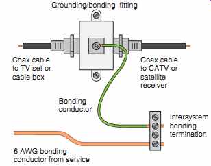
FIG. 13 Typical connection for the required grounding of the metal shield
on coaxial cable to the intersystem bonding termination.
===
The objective of grounding and bonding to the same grounding electrode as the main service ground is to reduce the possibility of having a difference of voltage potential between the two systems.
TELEPHONE WIRING (ARTICLE 800)
Since the deregulation of telephone companies, residential "do-it-yourself " telephone wiring has become quite common. The following is an over view of residential telephone wiring.
The NEC in 800.156 requires that for new dwelling unit construction, a minimum of one communications outlet shall be installed within the dwelling and cabled to the service provider demarcation point. Prior to the 2008 NEC, telephone outlets were not required but if installed, Article 800 spelled out the installation requirements.
The telephone company will install the service line to a residence and terminate at a protector device, as in FIG. 14. The protector protects the system from hazardous voltages. The protector may be mounted either outside or inside the home.
Different telephone companies have different rules.
Always check with the phone company before starting your installation.
The point where the telephone company ends and the homeowner's interior wiring begins is called the demarcation point, as shown in FIG. 14.
The preferred demarcation point is outside of the home, generally near the electric meter where proper grounding and bonding can be done. A network interface might be of the type depicted in FIG. 14. This is a combination unit that provides the compartment for the utility with con trolled access and an owner's compartment. The utility makes a connection from the grounding/ bonding terminal in the network interface unit to the intersystem bonding termination that is installed near the service equipment. The utility provides the dial tone to the customer's compartment. The customer can make connections of individual or multipair cables to the terminals provided.
===
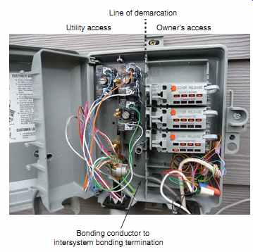
FIG. 14 Typical residential telephone network interface unit (NIU) installation.
The telephone company installs the NIU and connects the underground cable to
the protector in the NIU. The utility installs the bonding conductor to the
intersystem bonding terminal bar that is installed near the service equipment.
The customer installs the cable to the telephone outlet(s) and makes the connections
in the customer section of the NIU.
===
In the past, interior telephone wiring in homes was installed by the telephone company. Today, the responsibility for roughing-in the interior wiring is usually left up to the electrician. Telephone wiring is not to be run in the same raceway with electrical wiring. In addition, it cannot be installed in the same outlet and junction boxes as electrical wiring. Whatever the case, the rules found in Article 800 apply. Refer to FIGs. 14, 15, and 16.
For a typical residence, the electrician will rough in wall boxes wherever a telephone outlet is wanted. The boxes can be of the single-gang types illustrated in FIGs. 1, 2-11, 2-17, 2-19, and 2-32. Concealed telephone wiring in new homes is generally accomplished using multipair cables that are run from each telephone outlet to the customer compartment of the network interface unit. The cable can also take the form of a "loop system," as in FIG. 16. A 3-pair, 6-conductor twisted cable is shown in FIG. 17. There are some localities that require that these cables be run in a metal race way, such as EMT.