AMAZON multi-meters discounts AMAZON oscilloscope discounts
OBJECTIVES
• understand the basics of typical home warm air and hot water (hydronic) heating systems.
• understand and apply the NEC requirements for branch-circuit wiring for central heating systems.
• define all of the major components of typical heating systems.
• understand and apply the NEC requirements for Class 2 control circuit wiring.
In Section 23, we discussed various types of electric heating systems. In this section, we will take a look at gas- and oil-fired systems.
FORCED-WARM AIR FURNACES
Gas- and oil-fired heating systems provide the heat source for forced-warm air furnaces and hot water systems. Gas-fired, forced-warm air furnaces are the most common. Forced-warm air systems move hot air from the furnace through hot air ducts that in turn connect to hot air registers strategically located throughout the home. The room air is then pulled into cold air registers, returning to the furnace through cold air return ducts, where the air is again filtered, heated, and forced out through the hot air ducts.
Air-conditioning, humidity control, and fresh air intake are but a few of the things that can be added to a typical forced-warm air heating system.
HOT WATER SYSTEMS
Hot water systems move hot water through pipes to radiators (i.e., baseboards) and, in some instances, through tubing embedded in the ceiling or in the floor or on the underside of the floor to heat the floors from below. The water is returned to the boiler through a return pipe. Hot water systems are very adaptable to zone control by using a combination of one or more circulating pumps and/or valves for the different zones. Hot water heating systems are referred to as hydronic (wet) systems.
PRINCIPLE OF OPERATION
Most residential heating systems operate as follows.
A room thermostat is connected to the proper electrical terminals on the furnace or boiler. Inside the equipment, the various controls and valves are interconnected in a manner that will provide safe and adequate operation of the furnace.
Most residential heating systems are "packaged units" in which the burner, hot surface igniter or hot spark igniter, safety controls, valves, fan controls, sensors, high-temperature-limit switches, fan blower motor, blower fan speed control, draft inducer motor, primary and secondary heat exchanger, and so on, are preassembled, prewired parts of the furnace or boiler. Many of these items are included in an integrated printed circuit board module, which is the "brain" of the system. This module provides proper sequencing and safety features.
Older models have standing gas pilot lights and thermocouples.
Similar electronic circuitry is used in oil burners where the ignition, the oil burner motor, blower fan motor, high-temperature limit controls, hot water circulating pump in the case of hot water systems, and the other devices previously listed are all inter connected to provide a packaged oil burner unit.
Evaporator coils for air-conditioning purposes might be an integral part of the unit, or they might be mounted in the ductwork above the furnace.
Wiring a Residential Central Heating System
Gas- and oil-fired heating systems are usually "packaged units," which means that all of the internal wiring of the components has been done by the manufacturer of the unit.
In Section 23, we discussed the major NEC requirements for wiring an electric furnace.
For the electrician, the "field wiring" for a typical residential furnace or boiler consists of the following:
1. Installing and connecting the low-voltage wiring between the furnace and the thermostat.
This might be a cable consisting of two, three, four, or five small 18 AWG or 20 AWG conductors. Small knockouts are provided on the furnace through which the low-voltage Class 2 wires are brought into the furnace's wiring compartment (see FIG. 1). Class 2 wiring must not be run through the same raceway or cable as power wiring, 725.136(A).
2. Installing and connecting the branch-circuit power supply to the furnace. Knockouts are provided on the furnace through which the line voltage power supply is brought into the wiring compartment of the furnace. Depending on local codes, the line voltage power supply wiring might be in EMT, armored cable, or other accepted wiring methods (FIG. 1).
Disconnecting Means
The disconnecting means must be within sight of the furnace, 422.31, 422.32, 424.19, and 430.102.
The NEC defines "within sight" as being visible and not more than 50 ft (15 m) from the equipment the disconnect controls.
Some furnaces come with a disconnect switch.
If not, a toggle switch can be mounted on a box on the side of the furnace. This is simple for gas fired furnaces. Electric furnaces require a larger ampere-rated disconnect. Some electric furnaces come complete with circuit breakers that provide the overcurrent protection for the heating elements as required by UL Standard, and to serve as the disconnecting means required by the NEC.
The disconnecting means shall have an ampere rating not less than 125% of the total load of the motors and the heaters. If the disconnecting means (switch or circuit breaker) is required to have a lock off position, such as when the disconnecting means is not within sight of the equipment, then that disconnect provision for lock-off must remain in place with or without a lock installed.
===
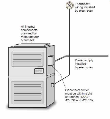
FIG. 1 Diagram showing thermostat wiring, power supply wiring, and disconnect
switch.
ANSI Standard Z21.47 does not allow cord-and-plug connections for a gas furnace.
Thermostat wiring installed by electrician Power supply installed by electrician Disconnect switch must be within sight of furnace, 422.31, 424.19, and 430.102.
All internal components prewired by manufacturer of furnace
===
Individual Branch Circuit Required
NEC 422.12 requires that central heating equipment be supplied by an individual branch circuit. By definition in the NEC, an individual branch circuit is A branch circuit that supplies only one utilization equipment.* The size of the branch circuit depends on the requirements of the particular furnace. A typical gas forced warm air furnace might require only a 120 volt, 15-ampere branch circuit, whereas an electric furnace requires a 240-volt branch circuit and much larger conductors. Instructions furnished with a given furnace will indicate the branch-circuit requirements.
Some typical wiring diagrams are shown in FIGs. 2, 3, 4(A), and 4(B). These wiring diagrams show the individual electrical components of a typical residential heating system. In older systems, many of these components were wired by the electrician. In newer systems, most components other than the thermostat are prewired as part of a packaged furnace or boiler. The manufacturer's literature includes detailed wiring diagrams for a given model.
===
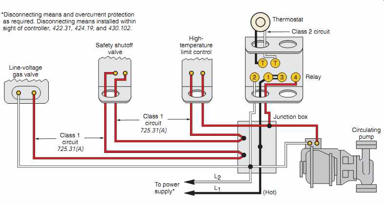
FIG. 2 Typical wiring diagram for a gas burner, forced hot water system.
Always consult the manufacturer's wiring diagram relating to a particular model
heating unit.
Line-voltage gas valve
Safety shutoff valve High temperature limit control
Thermostat Class 2 circuit
Relay Junction box (Hot)
To power supply* Class 1 circuit 725.31(A)
Circulating pump
Class 1 circuit 725.31(A)
*Disconnecting means and overcurrent protection as required.
Disconnecting means installed within sight of controller, 422.31, 424.19, and 430.102.
===
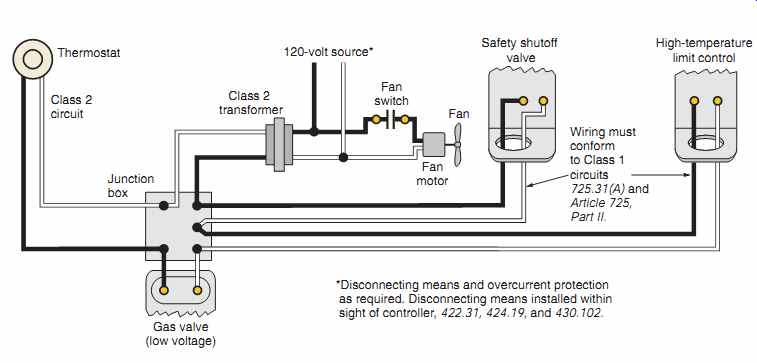
FIG. 3 Typical wiring diagram for a gas burner, forced-warm air system.
Always consult the manufacturer's wiring diagrams relating to a particular
model heating unit.
Gas valve (low voltage)
Safety shutoff valve Wiring must conform to Class 1 circuits 725.31(A) and Article 725, Part II.
High-temperature limit control; Thermostat; Class 2 circuit; Class 2 transformer 120-volt source*; Fan motor; Fan Junction box
*Disconnecting means and overcurrent protection as required. Disconnecting means installed within sight of controller, 422.31, 424.19, and 430.102.
Fan switch
===
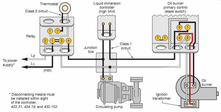
FIG. 4(A) Typical wiring diagram of an oil burner heating installation.
Always consult the manufacturer's wiring diagram relating to a particular model
heating unit.
Circulating pump Liquid immersion controller (high limit) Thermostat Relay (Hot) L2 L1 To power supply*
* Disconnecting means must be installed within sight of the controller, 422.31, 424.19, and 430.102.
Ignition transformer Oil burner Class 1 circuit Class 2 circuit Oil burner primary control (stack switch)
====
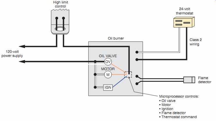
FIG. 4(B) An oil burner featuring an electronic microprocessor that controls
all facets of the burner operation. Most of the components are an integral
part of the unit, thus keeping field wiring to a minimum. All manufacturers
provide detailed wiring diagrams for their products.
Always consult the manufacturer's wiring diagrams relating to a particular model heating unit.
High limit control
120-volt power supply
Oil burner
MOTOR
Flame detector
Microprocessor controls:
- Oil valve
- Motor
- Ignition
- Flame detector
- Thermostat command Class 2 wiring 24-volt thermostat
===
MAJOR COMPONENTS
Gas- and oil-fired warm air systems and hot water boilers contain many individual components. Here is a brief description of these components.
Aquastat: An aquastat is a direct immersion water temperature thermostat that regulates boiler or tank temperature in hydronic heating systems, ensuring that the circulating water maintains proper, satisfactory temperature.
Cad Cell: A cad cell is a cadmium sulfide sensor for sensing flame. Cad cells have pretty much replaced the older style stack-mounted bimetal switches.
Circulating Pump: A circulating pump circulates hot water in a hydronic central heating system.
Control Circuit: A control circuit is any electric circuit that controls any other circuit through a relay or an equivalent device; also referred to as a remote control circuit.
Combustion Chamber: The combustion chamber surrounds the flame and radiates heat back into the flame to aid in combustion.
Combustion Head: A combustion head creates a specific pattern of air at the end of the air tube. The air is directed in such a way as to force oxygen into the oil spray so the oil can burn. A combustion head might also be referred to as the turbulator, fire ring, retention ring, or end cone.
Draft Regulator: A draft regulator is a counter weighted swinging door that opens and closes to help maintain a constant level of draft over the fire.
Fan Control: A fan control is used to control the blower fan on forced-warm air systems. On newer furnaces, the fan control is an electronic timer that starts the fan motor a given time in seconds after the main burner has come on. This timing ensures that the blower will blow warm air. Older type adjustable temperature fan controls are still around.
Fan Motor: The fan motor is the electric motor that forces warm air through the heating ducts. In typical residential heating systems, the motor is pro vided with integral overload protection. The motor may be single, multiple, or variable speed.
Flue: A flue is a channel in a chimney or a pipe for conveying flame and smoke to the outer air.
Heat Exchanger: A heat exchanger transfers the heat energy from the combustion gases to the air in the furnace or to the water in a boiler.
High-Temperature Limit Control: A high temperature limit control is a safety device that limits the temperature in the plenum of the furnace to some predetermined safe value as determined by the manufacturer. When this predetermined temperature is reached, the high-temperature limit control shuts off the power to the burner. In newer furnaces, the high-temperature limit control is part of an integrated circuit board and is communicated to by a sensor strategically located in the plenum. Older furnaces might have individual high-temperature limit controls and a separate fan control, or they might have combination high-temperature limit/fan controls.
Hot Surface Igniter: In furnaces that do not have a standing constant pilot light, the hot surface igniter heats to a cherry red/orange color. When it reaches the proper temperature, the main gas valve is allowed to open. If the hot surface igniter does not come on, the main gas valve will not open. Most energy-efficient furnaces use this concept for ignition.
Hydronic System: The hydronic system is a system of heating or cooling that involves transfer of heat by circulating fluid such as water in a closed system of pipes.
Ignition:
• Constant: The igniter is designed to stay on continuously.
• Intermittent Duty: Defined by UL 296 as "ignition by an energy source that is continuously maintained throughout the time the burner is firing." In other words, the igniter is on the entire time the burner is firing.
• Interrupted Duty: Defined by UL 296 as "an ignition system that is energized each time the main burner is to be fired and de-energized at the end of a timed trial for ignition period or after the main flame is proven to be established." In other words, the igniter comes on to light the flame; then, after the flame is established, the igniter is turned off and the main flame keeps burning.
Induced Draft Blower: When the thermostat calls for heat, the induced draft blower starts first to expel any gases remaining in the combustion chamber from a previous burning cycle. It continues to run, pulling hot combustion gases through the heat exchangers, then vents the gases to the outdoors.
Integrated Control: An integrated control is a printed circuit board containing many electronic components. When the thermostat calls for heat, the integrated circuit board takes over to manage the sequence of events that allow the burner to operate safely.
Liquid Immersion Control: This is also referred to as an aquastat. A liquid immersion control controls high water and circulating water temperature in a hot water system. A high-temperature limit control shuts off the burner when a predetermined dangerous high temperature is reached. When acting as a circulating water temperature control, this control makes sure that the water being circulated through the piping sys tem is at the desired temperature-not cold.
Low-Water Control: Also referred to as a low-water cutoff, this device senses low-water levels in a boiler.
When a low-water situation occurs, the low-water control shuts off the electrical power to the burner.
Main Gas Valve: The main gas valve is the valve that allows the gas to flow to the main burner of a gas-fired furnace. It may also function as a pres sure regulator, a safety shut-off, and as the pilot and main gas valve. Should there be a "flame-out," if the pilot light fails to operate, or in the event of a power failure, this valve will shut off the flow of gas to the main burner.
Nozzle: A nozzle produces the desired spray pat tern for the particular appliance in which the burner is used.
Oil Burner: The function of an oil burner is to break fuel oil into small droplets, mix the droplets with air, and ignite the resulting spray to form a flame.
Primary Control: A primary control controls the oil burner motor, ignition, and oil valve in response to commands from a thermostat. If the oil fails to ignite, the controller shuts down the oil burner.
Pump and Zone Controls: Pump and zone controls regulate the flow of water or steam in boiler systems to specific "zones" in the building.
Safety Controls: Safety controls such as pressure relief valves, high-temperature limit controls, low-water cutoffs, and burner primary controls protect against appliance malfunction.
Solenoid: A solenoid is an electrically operated device, which, when the valve coil is energized, a magnetic field is developed, causing a spring-loaded steel valve piston to overcome the resistance of the spring and immediately pull the piston into the stem.
The valve is now in the open position. When de energized, the solenoid coil magnetic field instantly dissipates, and the spring-loaded valve piston snaps closed, stopping oil flow or gas flow to the nozzle.
The flame is extinguished, allowing fuel to flow.
Usually a spring returns the valve back to the closed position.
Spark Ignition: In spark ignition systems, the spark comes on while pilot gas flows to the pilot orifice.
Once the pilot flame is "proven" through an electronic sensing circuit, the main gas valve opens. Once ignition takes place, the sensor will monitor and prove existence of a main flame. If for some reason the main flame goes off, the furnace shuts down. Energy efficient furnaces may use this concept for ignition.
Switching Relay: A switching relay is used between the low-voltage wiring and line-voltage wiring. When a low-voltage thermostat calls for heat, the relay "pulls in," closing the line-voltage contacts on the relay, which turns on the main power to the furnace or boiler. Usually relays have a built-in transformer that provides the low-voltage Class 2 control circuit.
Thermocouple: A thermocouple is used in systems having a standing pilot to hold open a gas valve pilot solenoid magnet. A thermocouple consists of two dissimilar metals connected together to form a circuit. The metals might be iron and copper, cop per and iron constantan, copper-nickel alloy and chrome-iron alloy, platinum and platinum-rhodium alloy, or chromel and alumel. The types of metals used depend on the temperatures involved. When one of the junctions is heated, an electrical current flows (FIG. 5). To operate, there must be a temperature difference between the metal junctions.
In a gas burner, the source of heat for the thermo couple is the pilot light. The cold junction of the thermocouple remains open and is connected to the pilot safety shut-off gas valve circuit. A single thermocouple develops a voltage of about 25 to 30 dc millivolts. Because of this extremely low voltage, circuit resistance is kept to a very low value.
Thermopile: More than one thermocouple connected in series is a thermopile. See FIG. 6.
The power output of a thermopile is greater than that of a single thermocouple-typically either 250 or 750 dc millivolts. For example, 10 thermo couples (25 dc millivolts each) connected in series result in a 250 dc millivolt thermopile. Twenty-six thermocouples connected in series result in a 750 dc millivolt thermopile.
Thermostat: A thermostat turns the heating/cooling system on and off. Programmable thermostats might have day/night setback settings, a clock, a dig ital thermometer, humidity control, ventilation, and filtration control. Thermostats are usually mounted approximately 52 in. (1.3 m) above the finished floor. Do not mount thermostats where influenced by drafts, air currents from hot or cold air registers, near fireplaces, near concealed hot or cold water pipes or ducts, in the direct rays of the sun, or on outside walls. See FIG. 7. Some thermostats contain a small vial of mercury that "tips," so the mercury closes the circuit by bridging the gap between the electrical contacts inside the vial. These thermostats must be kept perfectly level to ensure accuracy.
===
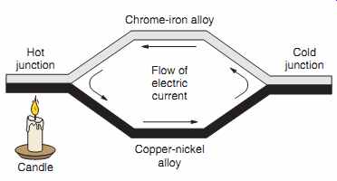
FIG. 5 Principle of a thermocouple.
Hot junction Candle Cold junction Chrome-iron alloy Flow of electric current Copper-nickel alloy
===
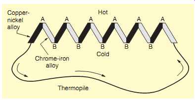
FIG. 6 Principle of a thermopile.
===
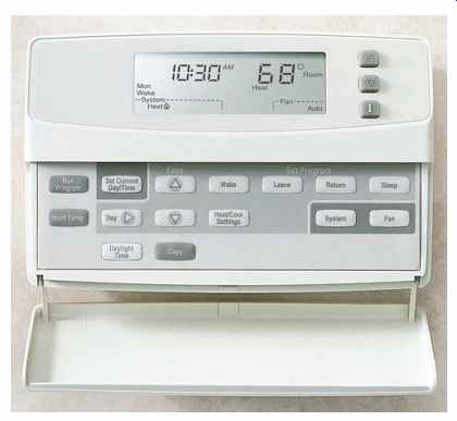
FIG. 7 A digital electronic programmable thermostat that provides proper
cycling of the heating system, resulting in comfort as well as energy savings.
This type of thermostat, depending on the model, can be programmed to control
temperature, time of operation, humidity, ventilation, filtration, circulation
of air, and zone control. Installation and operational instructions are furnished
with the thermostat.
===
WARNING: Do not throw mercury thermostats into the trash. The mercury is considered a hazardous waste material. They must be returned to a waste management organization for proper disposal.
Transformer: The transformer converts (transforms) the branch-circuit voltage to low voltage. For residential applications these are Class 2 transformers, 120 volts to 24 volts. The low-voltage wiring on the secondary of this transformer is Class 2 wiring.
Water Circulating Pump: In hydronic (wet) systems, a circulating pump circulates hot water through the piping system. Multizone systems have more than one pump, each controlled by a thermo stat for a particular zone. In multizone systems, a high-temperature control (aquastat) might be set to maintain the boiler water temperature to a specific temperature. Some multizone systems have one circulating pump and use electrically operated valves that open and close on command from the thermostat(s) located in a particular zone(s).
CLASS 2 CIRCUITS
Remote-control, signaling, and power-limited circuits fall into three categories-Class 1, Class 2, and Class 3.
Class 1, Class 2, and 3 circuits offer alternative wiring methods regarding voltage, power limitations, wire size, derating factors, overcurrent protection, physical protection, insulation, and materials that differentiate these types of circuits from conventional wiring methods, as covered in Section 1 through Section 4 in the NEC. FIG. 8 defines remote control, signaling, and power-limited terminology.
Low-voltage wiring in homes is generally Class 2 wiring. Class 2 wiring is very tolerant. We will limit our discussion to Class 2 wiring. Class 1 and Class 3 circuits are more restrictive than Class 2 circuits and are more commonly found in commercial and industrial applications. You can learn about Class 1 and Class 3 circuits in Article 725 in the NEC.
===
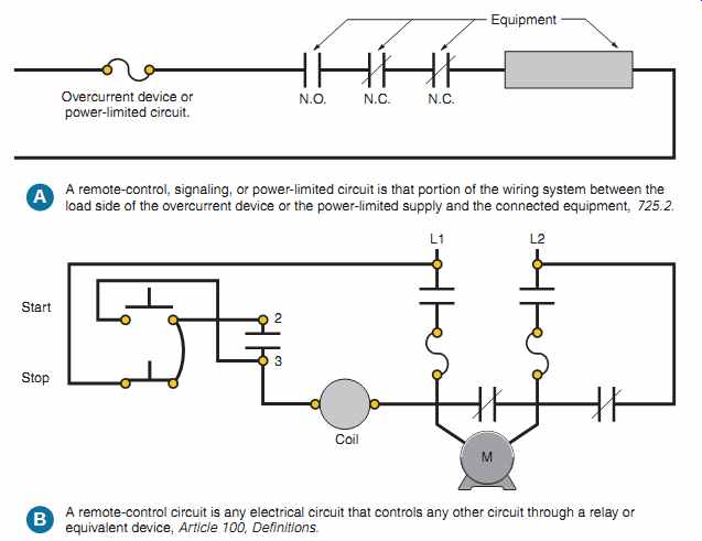
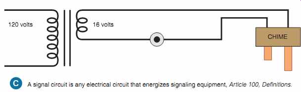
FIG. 8 The above diagrams explain a remote-control circuit and a signaling
circuit.
A. remote-control circuit is any electrical circuit that controls any other circuit through a relay or equivalent device, Article 100, Definitions.
B. Start 2 3 Coil Stop L1 L2 N.O. Overcurrent device or power-limited circuit.
Equipment N.C. N.C.
A remote-control, signaling, or power-limited circuit is that portion of the wiring system between the load side of the overcurrent device or the power-limited supply and the connected equipment, 725.2.
A signal circuit is any electrical circuit that energizes signaling equipment, Article 100, Definitions. C 16 volts CHIME 120 volts M
===
Wiring for Class 2 Circuits
Electricians describe wire and cable used for low-voltage wiring bell wire or thermostat wire.
What you are really looking for are listed Class 2 conductors and cables, referred to as CL2 or CL2X cables. Examples of Class 2 wiring are the low voltage conductors and cables used for heating and air conditioning, thermostats, security systems, remote control and signal wiring (chimes), intercom wiring, and other low-voltage applications.
Class 2 conductors are generally made of cop per, have a thermoplastic insulation, and have a volt age rating of not less than 150 volts as required by 725.129. Because the current required for Class 2 circuits is rather small, 18 AWG and 20 AWG conductors are most commonly used. Conductors as small as 24 AWG also are available; however, small conductors and long runs can result in voltage drop problems.
Multiconductor Class 2 cables consist of two to as many as 12 single conductors. These cables are available with or without a protective PVC outer jacket. The type with the outer jacket is preferred because there is less chance of damage to individual conductors, and it gives a neat appearance.
The conductors within these cables are color coded to make circuit identification easy. Table 1 is a table showing the color coding for the conductors in Class 2 cables.
Here is a summary of the NEC requirements for installing of Class 2 wiring:
• Class 2 circuits are "power-limited" and are considered to be safe from fire hazard and electric shock hazard.
• Class 2 wiring does not have to be in a raceway.
If a failure in the wiring should occur, such as a short circuit or an open circuit, there would not be a direct fire or shock hazard.
• Class 2 wiring is not permitted in the same raceway, cable, compartment, outlet box, or fitting with light and power conductors, 725.136(A). Even if the Class 2 conductors have the same 600-volt insulation as the power conductors, this is not permitted. See FIGs. 9 and 24-10. Manufacturers of heating and cooling equipment provide separate openings for bringing in the Class 2 wiring and separate openings for bringing in the power supply. NEC 725.136(D) addresses this issue.
• Keep Class 2 conductors at least 2 in. (50 mm) away from light or power wiring. This really pertains to old, open-knob-and-tube wiring.
Today, however, where light and power wiring is installed in Type NMC, Type AC, or in conduit, there is no problem, 725.136(I).
• Class 2 wiring shall not enter the same enclosure unless there is a barrier in the enclosure that separates the Class 2 wiring from the light and power conductors, 725.136(B).
• Class 2 circuits are inherently current limiting and do not require separate overcurrent protection. A Class 2 transformer is an example of this.
• Transformers that are intended to supply Class 2 circuits are listed and marked "Class 2 Transformer." These transformers have built-in overcurrent protection to pre vent overheating should a short circuit occur somewhere in the secondary winding or in the secondary circuit wiring. These transformers may be connected to branch circuits having overcurrent protection not more than 20 amperes, 725.127.
• Class 2 cables shall have a voltage rating of not less than 150 volts, 725.179(G).
===
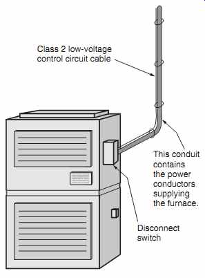
FIG. 10 The Code in 300.11(B)(2) and 725.143 allows Class 2 control circuit
conductors (cables) to be supported by the raceway that contains the power
conductors supplying electrical equipment, such as the furnace shown.
Disconnect switch
This conduit contains the power conductors supplying the furnace.
Class 2 low-voltage control circuit cable
===
Securing Class 2 Cables
• Class 2 cables must be installed in a neat and workmanlike manner and shall be adequately supported by the building structure in such a manner that they will not be damaged by nor mal building use, 725.24.
• Class 2 cables shall be attached to structural components by straps, staples, hangers, or similar fittings designed and installed so as not to damage the cable, 725.24.
• Class 2 cables may be secured directly to surfaces with insulated staples or may be installed in raceways.
• The insulation and jacket of Class 2 cables and conductors are rather thin. Be careful during installation not to pierce or crush the wires. Secure these cables and conductors with care, using the proper type of staples. Staple "guns" that use rounded staples are avail able. They straddle the cable nicely instead of flattening it, which might result in shorted-out wires.
• Do not support Class 2 cables from other race ways, cables, or nonelectric equipment. Taping, strapping, tie wrapping, hanging, or securing Class 2 cables to electrical raceways, piping, or ducts is generally prohibited, 725.143.
• NEC 725.143 refers back to 300.11(B)(2), which allows Class 2 conductors to be sup ported by the raceway that contains the power supply conductors for the same equipment that the Class 2 conductors are connected to. See FIG. 10.
• Do not run Class 2 conductors or cables through the same holes in studs and joists, holes that contain nonmetallic-sheathed cable, armored cable, raceways, conduits, or other pipes. There is too much chance of physical damage to the Class 2 cables.
====
TABLE 1
Table showing the color coding of Class 2 conductors and cables.
Number of Number of Conductors Color Conductors Color
1 Red 7 Orange
2 White 8 Black
3 Green 9 Pink
4 Blue 10 Gray
5 Yellow 11 Tan
6 Brown 12 Purple
====
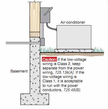
FIG. 9 Most residential air-conditioning units, furnaces, and heat pumps
have their low-voltage circuitry classified as Class 2. NEC 725.136(A) prohibits
installing low-voltage Class 2 conductors in the same raceway as the power
conductors, even if the Class 2 conductors have 600-volt insulation. Therefore,
the conduit running out of the basement wall in the above diagram would not
be permitted to contain both the 240-volt power conductors and the 24-volt
low-voltage Class 2 conductors. Always read the instructions furnished with
these types of appliances to be sure your wiring is in compliance with these
instructions, per 110.3(B) and the NEC. Review Section 4 for grounding methods.
Air-conditioner
Basement
Caution: If the low-voltage wiring is Class 2, keep separate from the power wiring, 725.136(A). If the low-voltage wiring is Class 1, it is acceptable to run with the power conductors, 725.48(B).
====
Class 2 Power Source Requirements
Class 2 power source voltage and current limitations, and overcurrent protection requirements, are found in Section 9, Table 11(A) and Table 11(B) of the NEC. You should refer to the nameplate data on Class 2 transformers, power supplies, and other equipment to verify that they are listed by a Nationally Recognized Testing Laboratory (NRTL) for a particular class.
REVIEW
1. The residence in this text is heated with:
a. gas.
b. electricity.
c. oil.
Circle the correct answer.
2. The NEC in , , , and requires that a disconnecting means be of the furnace.
3. The NEC in requires that a central heating system be supplied by a branch circuit.
4. In a home, the low-voltage wiring between the thermostat and furnace is
a. Class 1.
b. Class 2.
c. Class 3.
Circle the correct answer.
5. Class 2 circuits are -limited and are considered to be from hazard and from .
6. The nameplate on a transformer will indicate whether or not it is a Class 2 transformer.
(True) (False) Circle the correct answer.
7. If Class 2 conductors are insulated for 150 volts, and the power conductors are insulated for 600 volts, does the Code permit pulling these conductors through the same raceway?
(Yes) (No) Circle the correct answer. Give the NEC section number.
8. If you use 600-volt rated conductors for Class 2 wiring, does the Code permit pulling these conductors through the same raceway as the power conductors? (Yes) (No)
Circle the correct answer. Give the NEC section number.
9. The NEC is very strict about securing anything to electrical raceways. Name the Code sections that prohibit this practice. NEC
10. Does the Code permit attaching the low-voltage thermostat cable to the EMT that brings power to a furnace? (Yes) (No) Circle the correct answer. Give the NEC section numbers.
11. Explain what a thermocouple is and how it operates.
Prev. | Next
Similar Articles