AMAZON multi-meters discounts AMAZON oscilloscope discounts
<<cont. from part 1
The outer jacket is usually of a thermoplastic material. This outer jacket most often is a neutral color, such as white, light gray, or beige, that blends in with decorator colors in the home. This is particularly important in existing homes where the telephone cable may have to be exposed. Cables, mounting boxes, junction boxes, terminal blocks, jacks, adaptors, faceplates, cords, hardware, plugs, and so on, are all available through electrical distributors, builders' supply outlets, telephone stores, electronic stores, hardware stores, and similar wholesale and retail outlets. The selection of types of the preceding components is endless.
===
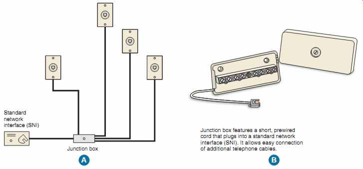
FIG. 15 (A) shows individual telephone cables run to each telephone outlet
from the common connection point. This is sometimes referred to as a star-wired
system. (B) shows a junction box for easy connection of multiple telephone
cables. Standard network interface (SNI); Junction box features a short, prewired
cord that plugs into a standard network interface (SNI). It allows easy connection
of additional telephone cables. Junction box A B
==
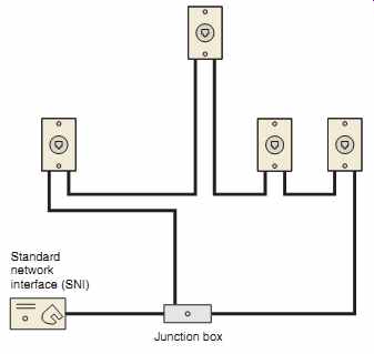
FIG. 16 A complete "loop system" (daisy-chain) of the telephone
cable. If something happens to one section of the cable, the circuit can be
fed from the other direction.
Standard network interface (SNI); Junction box
===
Telephone Conductors
The color coding of telephone cables is shown in FIG. 17. FIG. 18 shows some of the many types of telephone cords available.
Cables are available with various numbers of conductors. Here are a few:
2 pair . . . . 4 conductors 3 pair . . . . 6 conductors 4 pair . . . . 8 conductors 6 pair . . . 12 conductors 12 pair . . . 24 conductors
====
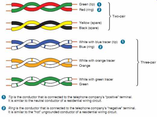
FIG. 17
Color coding for a 2-pair and a 3-pair, 6-conductor twisted telephone cable.
The color coding for 2-pair telephone cable stands alone. For three or more
pair cables, the color coding becomes WHITE/BLUE, WHITE/ORANGE, WHITE/GREEN,
WHITE/BROWN, WHITE/SLATE, RED/BLUE, RED/ORANGE, RED/GREEN, RED/BROWN, RED/SLATE,
BLACK/BLUE, BLACK/ORANGE, BLACK/ GREEN, BLACK/BROWN, BLACK/SLATE, YELLOW/BLUE,
YELLOW/ORANGE, YELLOW/GREEN, YELLOW/BROWN, YELLOW/SLATE, VIOLET/BLUE, VIOLET/ORANGE,
VIOLET/GREEN, VIOLET/ BROWN, VIOLET/SLATE. In multipair cables, the additional
pairs can be used for more telephones, fax machines, security reporting,
speakerphones, dialers, background music, and so on.
Green (tip) Red (ring); Two-pair Yellow (spare); Black (spare); White with blue tracer (tip); Blue (ring); White with orange tracer; Orange; White with green tracer;
1. Tip is the conductor that is connected to the telephone company’s ‘positive’ terminal. It is similar to the neutral conductor of a residential wiring circuit.
2. Ring is the conductor that is connected to the telephone company’s ‘negative’ terminal. It is similar to the ‘hot’ ungrounded conductor of a residential wiring circuit.
====
Telephone circuits require a separate pair of conductors from the telephone all the way back to the phone company's central switching center. To keep to a minimum interference that could come from other electrical equipment, such as electric motors and fluorescent fixtures, each pair of telephone wires (two wires) is twisted.
Installing Communication Wiring
When installing communication wiring and equipment, do it in a neat and workmanlike manner, not subject to physical damage when run on building surfaces. Secure cables with listed hardware, including straps, cable ties, and so on, 800.24. The requirements found in 300.4(D) (Cables and Raceways Parallel to Framing Members and Furring Strips) and 300.11 (Securing and Supporting) also apply to communication cables.
Cross-Talk Problems
A common telephone interference problem in homes is "cross-talk." This is apparent if you hear someone faintly talking in the background when you are using the telephone. Another problem is losing an online connection to your computer. The signals traveling in one pair of conductors are picked up by the adjacent pair of conductors in the cord or cable.
Quite often, these problems can be traced to older style flat (untwisted) 2-line telephone lines. Older style cables could carry audio signals quite well, but they are unsatisfactory for data transmission. These problems are virtually eliminated by using cables and cords that have conductors twisted at proper intervals, such as Category 5 cables. In FIG. 17, each pair of conductors is twisted, then all of the pairs are twisted again. Generally, you should avoid flat 2-line cords.
===
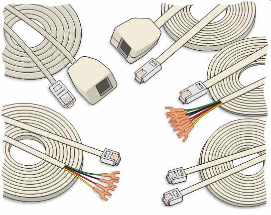
FIG. 18 Some of the many types of telephone cable available are illustrated.
Note that for ease of installation, the modular plugs and terminals have been
attached by the manufacturer of the cables. These cords are available in round
and flat configurations, depending upon the number of conductors in the cable.
===
The recommended circuit lengths are as follows:
24 AWG gauge-not over 200 ft (60 m)
22 AWG gauge-not over 250 ft (75 m)
Ringer Equivalence Number (REN)
Telephones, fax machines, answering machines, ringers, flashers, and so on, that have a sounder (ringer) are assigned an REN number. Generally, the maximum number of RENs on any single telephone line is 5. This maximum number of RENs ensures that all telephones will ring. When too many telephones are connected, the ring signal can become unreliable, resulting in devices failing to respond.
Older style electromechanical ringers were considered to be 1 REN. Electronic ringers have a minimal REN value. Mixing electromechanical and electronic ringers could present a problem as the electromechanical ringers tend to hog the current.
It all depends on your telephone line. Try it and see what happens.
Pay close attention to the total RENs connected in your home. REN values are found on the label of the device.
EXAMPLE
Four electronic telephones: 4 3 0.3 5 1.2 RENs One fax machine: 1.5 RENs One desk top telephone/
Answering machine: 0.7 REN One desk top telephone: 0.4 RENs Total 3.8 RENs
Call your telephone company if you think you have a problem because of too many telephones connected to one telephone line.
Plug-in or Permanent Connection? Most residential telephones plug into a jack of the type illustrated in FIGs. 19 and 20. It might be a good idea to have at least one permanently connected telephone, such as a wall phone in the kitchen. If all of the phones were of the plug-in type, it is possible (but highly unlikely) that all of them could be unplugged. As a result, there would be no audible signal.
===
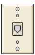
FIG. 19 Telephone modular jack.
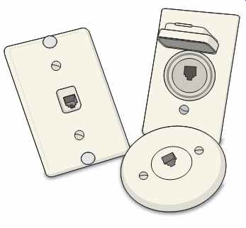
FIG. 20 Three styles of wall plates for modular telephone jacks: rectangular
stainless steel, weatherproof for outdoor use, and circular.
===
The electrical plans show that nine telephone outlets are provided as follows:
Front Bedroom 1
Kitchen 1
Laundry 1
Living Room 1
Master Bedroom 1
Rear Outdoor Patio 1
Recreation Room 1
Study/Bedroom 1
Workshop 1
Wireless Telephones
Wireless telephones have become all the rage! A master telephone unit is plugged into the telephone outlet somewhere in the house. The unit usually requires a power-supply transformer that plugs into a 120-volt receptacle outlet to power the telephone master unit. The master unit acts as a transmitter/receiver for the other remote telephones located at desirable locations. The master unit often provides services for the entire system, including answering machine, telephone number list, and intercom. Each of the remote telephones sits on a charging cradle and communicates to the wired telephone network by high-frequency radio signal.
Though very flexible, these telephones rely on power from the electric utility for operation. You should always have a telephone set that will function without reliance on 120-volt power for use during power outages, storms, and emergencies.
Installation of Telephone Cables (Article 800, Part V)
Telephone cables
1. are generally Type CM or Type CMX (for one- and two-family dwellings only), listed for telephone installations as being resistant to the spread of fire. See 800.154, 800.179(D), and 800.179(E). Also refer to Table 800.154(b) and Table 800.179 for other acceptable types.
2. shall be separated by at least 2 in. (50 mm) from light and power conductors unless the light and power conductors are in a raceway, or in nonmetallic-sheathed cable, Type AC cable, or Type UF cable, 800.133(A)(2).
3. shall not be placed in any conduit or boxes with electric light and power conductors unless the conductors are separated by a partition, 800.133(A)(1)(c).
4. do not support telephone cables from race ways that contain light and power conductors, 800.133(B).
5. should not share the same bored holes as electrical wiring, plumbing, gas pipes, and so on.
6. may be terminated in either metallic or non metallic boxes or plaster rings.
7. should be secured using rounded or depth-stop plastic staples. Do not use metal staples.
8. should not be installed using nail guns. Do not crush the cable.
9. should be kept away from hot water pipes, hot air ducts, and other heat sources that might harm the insulation.
10. should not be run in the same stud space as electrical branch-circuit wiring and should be kept at least 12 in. (300 mm) from power wiring where the cables are run parallel to the power wiring. These cautions were written before twisted pairs and category-rated cables entered the scene. With the advent of properly installed twisted and shielded cables, these "old wives' tale" recommendations from the past are probably not an issue.
Follow the specifications and instructions for the cable you are installing.
Raceway
In some communities, electricians prefer to install regular device boxes at a telephone outlet location, then "stub" a trade size ½ EMT to the basement or attic from this box. Then, at a later date, the telephone cable can be fished through the raceway.
Grounding (Article 800, Part IV) The telephone company will provide the proper grounding of their incoming cable sheath and primary protector, generally using an insulated conductor not smaller than 14 AWG copper or other corrosion resistant material, and not longer than 20 ft (6.0 m).
For one- and two-family dwellings, where it might be impractical to keep the grounding conductor 20 ft (6.0 m) or less, an additional communications grounding electrode must be installed.
This additional ground rod must be bonded to the power grounding electrode system with a bonding conductor not smaller than a 6 AWG copper. In just about all instances, all grounding and bonding of telephone equipment is done by the telephone company personnel. Many times, they clamp the primary protector to the grounded metal service raceway conduit to establish "ground." See 250.94.
Safety
Open-circuit voltage between conductors of an idle pair of telephone conductors is approximately 48 volts dc. The superimposed ringing voltage can reach 90 volts ac. Therefore, always work carefully with insulated tools and stay clear of bare terminals and grounded surfaces. Disconnect the interior telephone wiring if work must be done on the circuit, or take the phone off the hook, in which case the dc voltage level will drop to approximately 7 to 9 volts dc, and there should be no ac ringing voltage delivered.
Wiring for Computers and Internet Access
Wiring for telephones, high-speed Internet access, computers, television, printers, modems, security systems, intercoms, and similar home automation equipment could be thought of as one big project. Planning ahead is critical. Deciding on where this equipment is likely to be located will help you to design an entire voice/data/video system.
You will want to install Category 5 or Category 5e cables between each telephone outlet and a central distribution point so as to have the flexibility to connect the voice/data/video equipment in any configuration.
In addition to the previously mentioned equipment, there very well might be a scanner, an answering machine, desk lamps, floor lamps, a clock, an adding machine, a calculator, a television, a radio, a printer, CD/DVD/DVR/VCR/VHS players and burners, ZIP drives, and others. They draw little current, but all need to be plugged into a 120-volt receptacle! Managing and plugging in that many power cords is a major problem. Give consideration to installing two or three duplex or quadplex l20-volt receptacles at these locations. Multioutlet plug-in strips with surge protection will most likely be needed.
Section 31 contains much information about home automation and structured wiring.
Bringing Technology into Your Home
In most areas, the telephone or CATV company provides the entire "package" for homes. This might include digital local and long distance telephone service, Internet access, cable modems for personal computers, cable television, digital subscriber lines (DSL) (through existing copper telephone lines), and whatever other great new things may come next.
SIGNAL SYSTEM (CHIMES)
A signaling circuit is described in the NEC as any electric circuit that energizes signaling equipment. Signaling equipment includes such devices as chimes, doorbells, buzzers, code-calling systems, and signal lights.
===
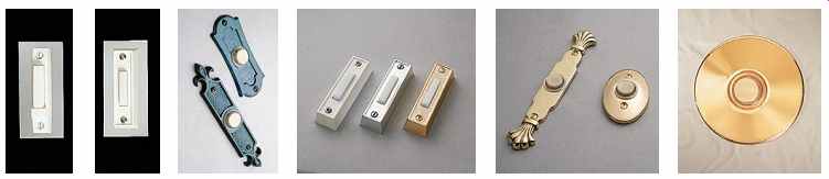
FIG. 21 Push buttons for door chimes.
===

FIG. 22 Typical residential door chimes.
===
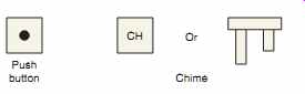
FIG. 23 Symbols for chimes and push buttons.
===
Door Chimes (Symbol CH )
Present-day dwellings use chimes rather than bells or buzzers to announce that someone is at a door. A musical tone is sounded rather than a harsh ringing or buzzing sound. Chimes are available in single-note, 2-note, 8-note (4-tube), and repeater tone styles. In a repeater tone chime, both notes sound as long as the push button is depressed. In an 8-note chime, contacts on a motor-driven cam are arranged in sequence to sound the notes of a simple melody when the chime button is pushed.
This type of chime is usually installed in dwellings having three entrances. The chime can be connected so that the 8-note melody sounds for the front door, two notes sound for the side door, and a single note sounds for the rear door. Chimes are also available with clocks and lights.
Electronic chimes may relay their chime tones through the various speakers of an intercom system.
When any chime is installed, the manufacturer's instructions must be followed.
The plans show that two chimes are installed in the residence. Two-note chimes are used. Each chime has two solenoids and two iron plungers.
When one solenoid is energized, the iron plunger is drawn into the opening of the solenoid. A plastic peg in the end of the plunger strikes one chime tone bar.
When the solenoid is de-energized, spring action returns the plunger, where it comes to rest against a soft felt pad so that it does not strike the other chime tone bar. Thus, a single chime tone sounds. As the second solenoid is energized, one chime tone bar is struck. When the second solenoid is de-energized, the plunger returns and strikes the second tone bar.
A two-tone signal is produced. The plunger then comes to rest between the two tone bars. Generally, two notes indicate front door signaling, and one note indicates rear or side door signaling.
FIG. 21 shows various push-button styles used for chimes. Many other styles are available.
FIG. 22 shows several typical residential type wall-mounted chimes. The symbols used to indicate push buttons and audible signals on the plans are shown in FIG. 23.
FIG. 24 shows how to provide proper backing for chimes. This is done during the rough-in stages of the electrical installation.
Chimes for the Hearing Impaired
Chimes for the hearing impaired are available with accessory devices that can turn on a dedicated lamp at the same time the chime is sounded. FIG. 25 shows the devices needed to accomplish this.
FIG. 26 shows the wiring details.
===
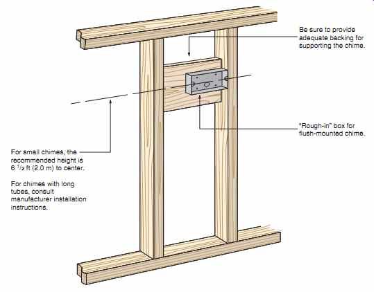
FIG. 24 Roughing-in for a flush-mounted chime.
Be sure to provide adequate backing for supporting the chime.
‘Rough-in’ box for flush-mounted chime.
For small chimes, the recommended height is 6 1/2 ft (2.0 m) to center.
For chimes with long tubes, consult manufacturer installation instructions.
===
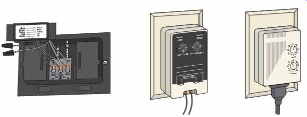
FIG. 25 Accessory devices can be attached to new or existing chimes to
provide visual signals when the chime is sounded. The first illustration shows
the module that is connected and mounted inside the chime. The second illustration
shows a transmitter that is plugged into a nearby receptacle. The third illustration
shows a receiver into which a lamp is plugged.
===
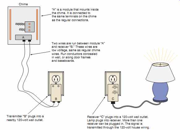
FIG. 26 Installation diagram for auxiliary devices for use with chimes
that can help the hearing impaired. When the chime sounds, the signal is transmitted
to the receiver, turning on the lamp that is plugged into the receiver. The "On" time
is adjustable at "C." The lamp should be a "dedicated" lamp
that lights up only when the chime sounds.
‘A’ is a module that mounts inside the chime. It is connected to the same terminals on the chime as the regular connections.
Two wires are run between module A and receiver B. These wires are low voltage, same as regular chime wires. Run conductors concealed in wall, or along door frames and baseboards.
Chime A Transmitter B plugs into a nearby 120-volt wall outlet.
Receiver C plugs into a 120-volt wall outlet.
Lamp plugs into receiver. More than one receiver can be plugged in. The signal is transmitted through the 120-volt house wiring.
====
Chime Transformers
===
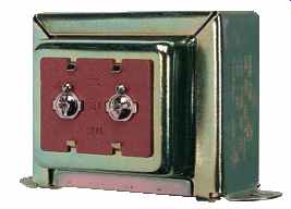
FIG. 27 Chime transformer.
Chime transformers are covered under UL Standard 1585. Because of their low-voltage rating and power limitation, they are listed as Class 2 transformers. The low-voltage wiring on the secondary side of the transformer is Class 2 wiring. Class 2 circuits are discussed in Section 24 and in Article 725.
FIG. 27 shows a chime transformer. The top view shows the 120-volt leads. Note the small set screw for ease of mounting into a conduit knock out in an outlet box. The bottom view shows the low-voltage terminals.
Chime transformers used in dwellings are generally rated 16 volts. They have built-in thermal over load protection. Should a short circuit occur in the low-voltage wiring, the overload device opens and closes repeatedly until the short circuit is cleared.
The UL standard requires that all metal parts of a transformer be properly grounded. To accomplish this, some chime transformers have a bare copper equipment grounding conductor in addition to the black and white supply conductors. Internal to the transformer, this equipment grounding conductor is connected to the metal parts (laminations) of the transformer. This bare equipment grounding conductor must be connected to the equipment grounding conductor or grounding screw in the outlet box.
Do not connect this equipment grounding conductor to the branch-circuit grounded (white) conductor.
Some chime transformers are marked "Install in Metal Box Only."
Additional Chimes
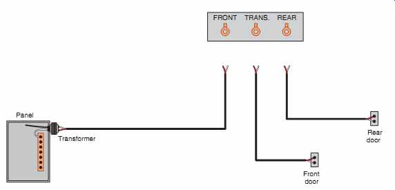
To extend a chime system to cover a larger area, a second or third chime may be added. In the residence, two chimes are used: one chime is mounted in the front hall and a second (extension) chime is mounted in the recreation room. The extension chime is wired in parallel to the first chime. The wires are run from one chime terminal board to the terminal board of the other chime. The terminals are connected as follows: transformer to transformer, front to front, and rear to rear, FIG. 28.
When more than one chime is installed, it will probably be necessary to install a transformer with a higher volt-ampere (wattage) rating. Do not install a transformer with a higher voltage rating. Check the manufacturers' instructions furnished with the chime transformer.
Do not add another transformer to an existing transformer to solve the problem of multiple chimes not responding properly. The NEC in 725.121(B) prohibits connecting transformers in parallel unless specifically listed for interconnection. Residential chime transformers are not listed for interconnection.
If a buzzer (or bell) and a chime are connected to a single transformer and are used at the same time, the transformer will put out a fluctuating voltage.
This condition does not allow either the buzzer or the chime to operate properly. The use of a trans former with a larger rating may solve this problem.
The wattage consumption of chimes varies with the manufacturer. Typical ratings are shown in Table 1.
Transformers with ratings of 5, 10, 15, 20, and 30 watts (VA) are available. For a multiple chime installation, wattage ratings for the individual chimes are added. The total value is the minimum trans former rating needed to do the job properly.
Low-Voltage Wiring --The low-voltage wiring for a chime(s) is classified as Class 2 wiring, as discussed in Section 24.
Wiring the Chime --The circuit shown in FIG. 28 is recommended for this chime installation because it provides a "hot" low-voltage circuit at the front hall location.
However, it is not the only way in which these chimes may be connected.
===
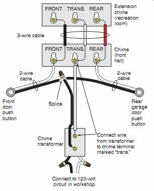
FIG. 28 Circuit for chime installation.
===
TABLE 1: Typical chimes with their power consumption.
Type of Chime | Power Consumption
Standard 2-note 10 watts
Repeating chime 10 watts
Internally lighted, two lamps 10 watts
Internally lighted, four lamps 15 watts
Combination chime and clock 15 watts
Motor-driven chime 15 watts
Electronic chime 15 watts
Programmable musical 15 watts
===
FIG. 28 shows that a 2-wire cable runs from the transformer in the utility room to the front hall chime. A 2-wire cable then runs from the chime to both the front and rear door push buttons. A 3-wire cable also runs between the front hall chime and the recreation room chime. Because of the "hot" low voltage circuit at the front hall location, a chime with a built-in clock can be used. A 4-conductor cable may be run to the extension chime so that the owner may install a clock-chime at this location also.
The plans show that the chime transformer is mounted into the knockout on one of the ceiling boxes in the utility room. The line-voltage connections are easy to make here. Some electricians prefer to mount the chime transformer on the top or side of the distribution panelboards. The electrician decides where to mount the transformer after considering the factors of convenience, economy, and good wiring practice.
Don't Conceal Boxes!
It may seem obvious, but the issue of accessibility bears repeating. Electrical equipment junction boxes and conduit bodies must be accessible, 314.29. It is permitted to have certain electrical equipment such as a chime transformer, junction boxes, and conduit bodies above a dropped lay-in ceiling because these are accessible by dropping out a ceiling panel. Never install electrical equipment, junction boxes, or conduit boxes above a permanently closed-in ceiling or within a wall. There may come a time when the electrical equipment and junction boxes need to be accessed. This includes chime transformers.
REVIEW
Note: Refer to the Code or the plans where necessary.
TELEVISION CIRCUIT
1. How many television outlets are installed in this residence?
2. Which type of television cable is commonly used and recommended?
3. What determines the design of the faceplates used?
4. What must be provided when installing a television outlet and receptacle outlet in one wall box?
5. From a cost standpoint, which system is more economical to install: a master amplifier distribution system or a multiset coupler? Explain the basic differences between these two systems.
6. How many wires are in the cable used between a rotor and its controller?
7. Digital satellite systems use an antenna that is approximately (18 in. [450 mm]) (36 in. [900 mm]) (72 in. [1.8 mm]) in diameter. Circle the correct answer.
8. List the requirements for cable television inside the house.
9. Which article of the Code references the requirements for cable community television installation?
10. It is generally understood that grounding and bonding together all metal parts of an electrical system and the metal shield of the cable television cable to the same grounding reference point in a residence will keep both systems at the same voltage level should a surge, such as lightning, occur. Therefore, if the incoming cable that has been installed by the CATV cable company installer has the metal shield grounded to a driven ground rod, does this installation conform to the NEC?
11. All television satellites rotate above the Earth in (the same orbit) (different orbits). Circle the correct answer.
12. Television satellites are set in orbit (10,000) (18,000) (22,245) miles above the Earth, which results in their rotating around the Earth at (precisely the same) (different) rotational speed as the Earth rotates. This is done so that the satellite "dish" can be focused on a specific satellite (once) (one time each month) (whenever the television set is used). Circle the correct answers.
13. Which section of the Code prohibits supporting coaxial cables from raceways that contain light or power conductors? NEC
14. When hooking up one CATV cable and another cable from an outdoor antenna to a receiver that has only one antenna input terminal, a(n) switch is usually installed.
TELEPHONE SYSTEM
1. How many locations are provided for telephones in the residence?
2. At what height are the telephone outlets in this residence mounted? Give measurement to center.
3. Sketch the symbol for a telephone outlet.
4. Is the telephone system regulated by the NEC?
5. a. Who is to furnish the outlet boxes required at each telephone outlet?
b. Who is to furnish the faceplates?
6. Who is to furnish the telephones?
7. Who does the actual installation of the telephone equipment?
8. How are the telephone cables concealed in this residence?
9. The point where the telephone company's cable ends and the interior telephone wiring meets is called the point. The device installed at this point is called a(n) .
10. What are the colors contained in a four-conductor telephone cable assembly and what are they used for?
11. Itemize the Code rules for the installation of telephone cables in a residence.
12. If finger contact were made between the red conductor and green conductor at the instant a "ring" occurs, what shock voltage would be felt?
13. What section of the Code prohibits supporting telephone wires from raceways that contain light or power conductors? NEC
14. The term cross-talk is used to define the hearing of the faint sound of voices in the back ground when you are using the telephone. Cross-talk can be reduced significantly by running (flat cables) (twisted pair cables) to the telephones. Circle the correct answer.
15. Which section of the Code prohibits telephone cables from being installed in the same box or enclosure or from being pulled into the same raceway as light and power circuits?
SIGNAL SYSTEM
1. What is a signal circuit?
2. What style of chime is used in this residence?
3. a. How many solenoids are contained in a 2-tone chime?
b. What closes the circuit to the solenoid of a chime?
4. Explain briefly how two notes are sounded by depressing one push button (when two solenoids are provided).
5. a. Sketch the symbol for a push button.
b. Sketch the symbol for a chime.
6. a. At what voltage do residence chimes generally operate?
b. How is this voltage obtained?
7. What is the maximum volt-ampere rating of transformers supplying Class 2 systems?
8. What two types of chime transformers for Class 2 systems are listed by UL?
9. Is the extension chime connected with the front hall chime in series or in parallel?
10. How many bell wires terminate at
a. the transformer?
b. the front hall chime?
c. the extension chime?
d. each push button?
11. a. What change in equipment may be necessary when more than one chime is connected to sound at the same time on one circuit?
b. Why?
12. What type of insulation is usually found on low-voltage wires?
13. What size wire is installed for signal systems of the type in this residence?
14. a. How many wires are run between the front hall chime and the extension chime in the recreation room?
b. How many wires are required to provide a "hot" low-voltage circuit at the extension chime?
15. Why is it recommended that the low-voltage secondary of the transformer be run to the front hall chime location and separate 2-wire cables be installed to each push button?
16. a. Is it permissible to install low-voltage Class 2 systems in the same raceway or enclosure with light and proper wiring?
b. Which Code section covers this?
17. a. Where is the transformer in the residence mounted?
b. To which circuit is the transformer connected?
18. a. How many feet of 2-conductor bell wire cable are required?
b. How many feet of 3-conductor bell wire cable are required?
19. How many insulated staples are needed for the bell wire if it is stapled every 24 in. (600 mm)?
20. Should low-voltage bell wire be pulled through the same holes in studs and joists that also contain nonmetallic-sheathed cable?
21. What section of the Code prohibits supporting fire alarm conductors from raceways that contain light or power conductors? NEC .
22. Complete this typical chime wiring diagram using colored pencils. The 2-wire, low-voltage cables contain one red and one white conductor. Use yellow to represent the white conductors.