AMAZON multi-meters discounts AMAZON oscilloscope discounts
. (<< cont.from part 1 )
DUST
COLLECTORS
This section identifies common problems and their causes for baghouse and cyclonic separator dust-collection systems.
1. Baghouses:
TBL. 12 lists the common failure modes for baghouses. This guide may be used for all such units that use fabric filter bags as the primary dust-collection media.
2. Cyclonic Separators:
TBL. 13 identifies the failure modes and their causes for cyclonic separators.
Because there are no moving parts within a cyclone, most of the problems associated with this type of system can be attributed to variations in process parameters, such as flowrate, dust load, dust composition (e.g., density, size), and ambient conditions (e.g., temperature, humidity).
FIG. 1 (not shown) Unbalanced inertial forces and couples for various reciprocating compressors.
======
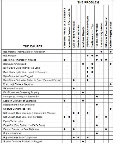
TBL. 12 Common Failure Modes of Baghouses
THE PROBLEM:
Continuous Release of Dust-Laden Air Intermittent Release of Dust-Laden Air Loss of Plant Air Pressure Blow-Down Ineffective Insufficient Capacity Excessive Differential Pressure Fan/Blower Motor Trips Fan Has High Vibration Premature Bag Failures Differential Pressure Too Low Chronic Plugging of Bags
THE CAUSES:
Bag Material Incompatible for Application Bag Plugged Bag Torn or Improperly Installed Baghouse Undersized Blow-Down Cycle Interval Too Long Blow-Down Cycle Time Failed or Damaged Blow-Down Nozzles Plugged Blow-Down Pilot Valve Failed to Open (Solenoid Failure) Dust Load Exceeds Capacity Excessive Demand Fan/Blower Not Operating Properly Improper or Inadequate Lubrication Leaks in Ductwork or Baghouse Misalignment of Fan and Motor Moisture Content Too High Not Enough Blow-Down Air (Pressure and Volume) Not Enough Dust Layer on Filter Bags Piping/Valve Leaks Plate-Out (Dust Build-up on Fan's Rotor) Plenum Cracked or Seal Defective Rotor Imbalanced Ruptured Blow-Down Diaphragms Suction Ductwork Blocked or Plugged
=======
PROCESS ROLLS
Most of the failures that cause reliability problems with process rolls can be attributed to either improper installation or abnormal induced loads. TBL. 14 identifies the common failure modes of process rolls and their causes.
Installation problems are normally the result of misalignment where the roll is not perpendicular to the travel path of the belt or transported product. If process rolls are misaligned, either vertically or horizontally, the load imparted by the belt or carried product is not uniformly spread across the roll face or to the support bearings. As a result, both the roll face and bearings are subjected to abnormal wear and may prematurely fail.
Operating methods may cause induced loads that are outside the acceptable design limits of the roll or its support structure. Operating variables, such as belt or strip tension or tracking, may be the source of chronic reliability problems. As with mis alignment, these variables apply an unequal load distribution across the roll face and bearing-support structure. These abnormal loads accelerate wear and may result in premature failure of the bearings or roll.
GEARBOXES/REDUCERS
This section identifies common gearbox (also called a reducer) problems and their causes. TBL. 15 lists the more common gearbox failure modes. One of the primary causes of failure is the fact that, with few exceptions, gear sets are designed for operation in one direction only. Failure is often caused by inappropriate bidirectional operation of the gearbox or backward installation of the gear set. Unless specifically manufactured for bidirectional operation, the "nonpower" side of the gear's teeth is not finished. Therefore, this side is rougher and does not provide the same tolerance as the finished "power" side.
==========
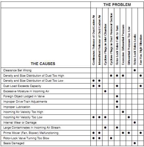
TBL. 13 Common Failure Modes of Cyclonic Separators
THE PROBLEM:
Continuous Release of Dust-Laden Air Intermittent Release of Dust-Laden Air Cyclone Plugs in Inlet Chamber Cyclone Plugs in Dust Removal Section Rotor-Lock Valve Fails to Turn Excessive Differential Pressure Differential Pressure Too Low Rotor-Lock Valve Leaks Fan Has High Vibration
THE CAUSES:
Clearance Set Wrong Density and Size Distribution of Dust Too High Density and Size Distribution of Dust Too Low Dust Load Exceeds Capacity Excessive Moisture in Incoming Air Foreign Object Lodged in Valve Improper Drive-Train Adjustments Improper Lubrication Incoming Air Velocity Too High Incoming Air Velocity Too Low Internal Wear or Damage Large Contaminates in Incoming Air Stream Prime Mover (Fan, Blower) Malfunctioning Rotor-Lock Valve Turning Too Slow Seals Damaged
==========
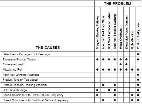
TBL. 14 Common Failure Modes of Process Rolls
THE PROBLEM:
Frequent Bearing Failures Abnormal Roll Face Wear Roll Neck Damage or Failure Abnormal Product Tracking Motor Overheats Excessive Power Demand High Vibration Product Quality Poor
THE CAUSES:
Defective or Damaged Roll Bearings Excessive Product Tension Excessive Load Misaligned Roll Poor Roll Grinding Practices Product Tension Too Loose Product Tension/Tracking Problem Roll Face Damage Speed Coincides with Roll's Natural Frequency Speed Coincides with Structural Natural Frequency
========
Note that it has become standard practice in some plants to reverse the pinion or bull gear in an effort to extend the gear set's useful life. Although this practice permits longer operation times, the torsional power generated by a reversed gear set is not as uniform and consistent as when the gears are properly installed.
Gear overload is another leading cause of failure. In some instances, the overload is constant, which is an indication that the gearbox is not suitable for the application. In other cases, the overload is intermittent and occurs only when the speed changes or when specific production demands cause a momentary spike in the torsional load requirement of the gearbox.
Misalignment, both real and induced, is also a primary root-cause of gear failure. The only way to ensure that gears are properly aligned is to hard blue the gears immediately after installation. After the gears have run for a short time, their wear pattern should be visually inspected. If the pattern does not conform to vendor's specifications, alignment should be adjusted.
Poor maintenance practices are the primary source of real misalignment problems.
Proper alignment of gear sets, especially large ones, is not an easy task. Gearbox manufacturers don’t provide an easy, positive means to ensure that shafts are parallel and that the proper center-to-center distance is maintained.
Induced misalignment is also a common problem with gear drives. Most gearboxes are used to drive other system components, such as bridle or process rolls. If mis alignment is present in the driven members (either real or process induced), it will also directly affect the gears. The change in load zone caused by the misaligned driven component will induce misalignment in the gear set. The effect is identical to real misalignment within the gearbox or between the gearbox and mated (i.e., driver and driven) components.
Visual inspection of gears provides a positive means to isolate the potential root-cause of gear damage or failures. The wear pattern or deformation of gear teeth provides clues about the most likely forcing function or cause. The following sections discuss the clues that can be obtained from visual inspection.
==================
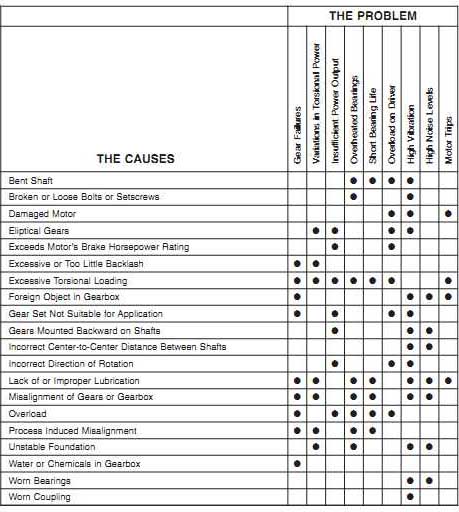
TBL. 15 Common Failure Modes of Gearboxes and Gear Sets
THE PROBLEM:
Gear Failures Variations in Torsional Power Insufficient Power Output Overheated Bearings Short Bearing Life Overload on Driver High Vibration High Noise Levels Motor Trips
THE CAUSES:
Bent Shaft Broken or Loose Bolts or Setscrews Damaged Motor Elliptical Gears Exceeds Motor's Brake Horsepower Rating Excessive or Too Little Backlash Excessive Torsional Loading Foreign Object in Gearbox Gear Set Not Suitable for Application Gears Mounted Backward on Shafts Incorrect Center-to-Center Distance Between Shafts Incorrect Direction of Rotation Lack of or Improper Lubrication Misalignment of Gears or Gearbox Overload Process Induced Misalignment Unstable Foundation Water or Chemicals in Gearbox Worn Bearings Worn Coupling
=================
1. Normal Wear
FIG. 2 illustrates a gear that has a normal wear pattern. Note that the entire surface of each tooth is uniformly smooth above and below the pitch line.
2. Abnormal Wear
FIGS. 3 through 5 illustrate common abnormal wear patterns found in gear sets. Each of these wear patterns suggests one or more potential failure modes for the gearbox.
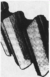
FIG. 2 Normal wear pattern.
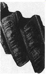
FIG. 3 Wear pattern caused by abrasives in lubricating oil.
Abrasion:
Abrasion creates unique wear patterns on the teeth. The pattern varies depending on the type of abrasion and its specific forcing function. FIG. 3 illustrates severe abrasive wear caused by particulates in the lubricating oil. Note the score marks that run from the root to the tip of the gear teeth.
Chemical Attack or Corrosion:
Water and other foreign substances in the lubricating oil supply also cause gear degradation and premature failure. FIG. 4 illustrates a typical wear pattern on gears caused by this failure mode.
Overloading:
The wear patterns generated by excessive gear loading vary, but all share similar components. FIG. 5 illustrates pitting caused by excessive torsional loading. The pits are created by the implosion of lubricating oil. Other wear patterns, such as spalling and burning, can also help identify specific forcing functions or root-causes of gear failure.
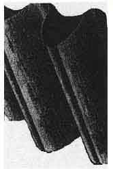
FIG. 4 Pattern caused by corrosive attack on gear teeth.
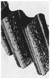
FIG. 5 Pitting caused by gear overloading.
STEAM TRAPS
Most of the failure modes that affect steam traps can be attributed to variations in operating parameters or improper maintenance. TBL. 16 lists the more common causes of steam trap failures.
Operation outside the trap's design envelope results in loss of efficiency and may result in premature failure. In many cases, changes in the condensate load, steam pressure or temperature, and other related parameters are the root-cause of poor performance or reliability problems. Careful attention should be given to the actual versus design system parameters. Such deviations are often the root-causes of problems under investigation.
Poor maintenance practices or the lack of a regular inspection program may be the primary source of steam trap problems. It’s important for steam traps to be routinely inspected and repaired to ensure proper operation.
INVERTERS
TBL. 17 lists the common symptoms and causes of inverter problems. Most of these problems can be attributed to improper selection for a particular application.
Others are caused by improper operation. When evaluating inverter problems, careful attention should be given to recommendations found in the vendor's operations and maintenance manual. These recommendations are often extremely helpful in isolating the true root-cause of a problem.
CONTROL VALVES
Although there are limited common control valve failure modes, the dominant problems are usually related to leakage, speed of operation, or complete valve failure. TBL. 18 lists the more common causes of these failures.
Special attention should be given to the valve actuator when conducting a root cause failure analysis. Many of the problems associated with both process and fluid-power control valves are really actuator problems. In particular, remotely con trolled valves that use pneumatic, hydraulic, or electrical actuators are subject to actuator failure. In many cases, these failures are the reason a valve fails to properly open, close, or seal. Even with manually controlled valves, the true root-cause can be traced to an actuator problem. For example, when a manually operated process control valve is jammed open or closed, it may cause failure of the valve mechanism.
This over-torquing of the valve's sealing device may cause damage or failure of the seal, or it may freeze the valve stem. Either of these failure modes results in total valve failure.
========
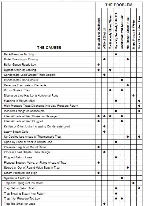
TBL. 16 Common Failure Modes of Steam Traps
THE PROBLEM:
Trap Will Not Discharge Will Not Shut-off Continuously Blows Steam Capacity Suddenly Falls Off Condensate Will Not Drain Not Enough Steam Heat Traps Freeze in Winter Back Flow in Return Line
THE CAUSES:
Back-Pressure Too High Boiler Foaming or Priming Boiler Gauge Reads Low Bypass Open or Leaking Condensate Load Greater Than Design Condensate Short-Circuits Defective Thermostatic Elements Dirt or Scale in Trap Discharge Line Has Long Horizontal Runs Flashing in Return Main High-Pressure Traps Discharge into Low-Pressure Return Incorrect Fittings or Connectors Internal Parts of Trap Broken or Damaged Internal Parts of Trap Plugged Kettles or Other Units Increasing Condensate Load Leaky Steam Coils No Cooling Leg Ahead of Thermostatic Trap Open By-Pass or Vent in Return Line Pressure Regulator Out of Order Process Load Greater Than Design Plugged Return Lines Plugged Strainer, Valve, or Fitting Ahead of Trap Scored or Out-of-Round Valve Seat in Trap Steam Pressure Too High System Is Air-Bound Trap and Piping Not Insulated Trap Below Return Main Trap Blowing Steam into Return Trap Inlet Pressure Too Low Trap Too Small for Load
========
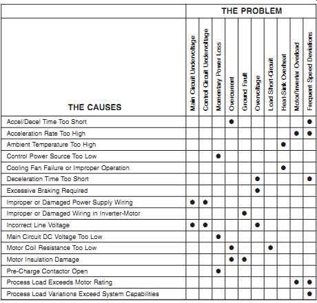
TBL. 17 Common Failure Modes of Inverters
THE PROBLEM:
Main Circuit Undervoltage Control Circuit Undervoltage Momentary Power Loss Overcurrent Ground Fault Overvoltage Load Short-Circuit Heat-Sink Overheat Motor/Inverter Overload Frequent Speed Deviations
THE CAUSES:
Accel/Decel Time Too Short Acceleration Rate Too High Ambient Temperature Too High Control Power Source Too Low Cooling Fan Failure or Improper Operation Deceleration Time Too Short Excessive Braking Required Improper or Damaged Power Supply Wiring Improper or Damaged Wiring in Inverter-Motor Incorrect Line Voltage Main Circuit DC Voltage Too Low Motor Coil Resistance Too Low Motor Insulation Damage Pre-Charge Contactor Open Process Load Exceeds Motor Rating Process Load Variations Exceed System Capabilities
=============
SEALS AND PACKING
Failure modes that affect shaft seals are normally limited to excessive leakage and premature failure of the mechanical seal or packing. TBL. 19 lists the common failure modes for both mechanical seals and packed boxes. As the table indicates, most of these failure modes can be directly attributed to misapplication, improper installation, or poor maintenance practices.
1. Mechanical Seals
By design, mechanical seals are the weakest link in a machine-train. If there is any misalignment or eccentric shaft rotation, the probability of a mechanical seal failure is extremely high. Most seal tolerances are limited to no more than 0.002 inches of total shaft deflection or misalignment. Any deviation outside of this limited range will cause catastrophic seal failure.
=========
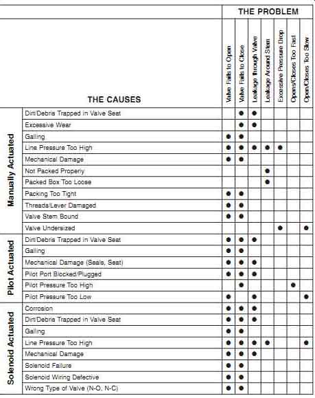
TBL. 18 Common Failure Modes of Control Valves
THE PROBLEM:
Valve Fails to Open Valve Fails to Close Leakage through Valve Leakage Around Stem Excessive Pressure Drop Opens/Closes Too Fast Open/Closes Too Slow
THE CAUSES:
Dirt/Debris Trapped in Valve Seat Excessive Wear Galling Line Pressure Too High Mechanical Damage Not Packed Properly Packed Box Too Loose Packing Too Tight Threads/Lever Damaged Valve Stem Bound Valve Undersized Dirt/Debris Trapped in Valve Seat Galling Mechanical Damage (Seals, Seat) Pilot Port Blocked/Plugged Pilot Pressure Too High Pilot Pressure Too Low Corrosion Dirt/Debris Trapped in Valve Seat Galling Line Pressure Too High Mechanical Damage Solenoid Failure Solenoid Wiring Defective Wrong Type of Valve (N-O, N-C) Solenoid Actuated Pilot Actuated Manually Actuated
==========
Misalignment ---Physical misalignment of a shaft will either cause seal damage or permit some leakage through the seal, or it will result in total seal failure. Therefore, it’s imperative that good alignment practices be followed for all shafts that have an installed mechanical seal.
========
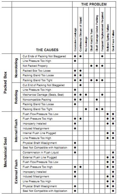
TBL. 19 Common Failure Modes of Packing and Mechanical Seals.
THE PROBLEM:
Excessive Leakage Continuous Stream of Liquid No Leakage Shaft Hard to Turn Shaft Damage Under Packing Frequent Replacement Required Bellows Spring Failure Seal Face Failure
THE CAUSES:
Cut Ends of Packing Not Staggered Line Pressure Too High Not Packed Properly Packed Box Too Loose Packing Gland Too Loose Packing Gland Too Tight Cut End of Packing Not Staggered Line Pressure Too High Mechanical Damage (Seals, Seat) Non-compatible Packing; Packing Gland Too Loose Packing Gland Too Tight Flush Flow/Pressure Too Low Flush Pressure Too High Improperly Installed Induced Misalignment Internal Flush Line Plugged Line Pressure Too High Physical Shaft Misalignment Seal Not Compatible with Application Contamination in Flush Liquid External Flush Line Plugged Flush Flow/Pressure Too Low Flush Pressure Too High Improperly Installed Induced Misalignment Line Pressure Too High Physical Shaft Misalignment Seal Not Compatible with Application Mechanical Seal Packed Box External Flush Internal Flush Rotating Nonrotating
=========
Process- and machine-induced shaft instability also create seal problems. Primary causes for this failure mode include aerodynamic or hydraulic instability, critical speeds, mechanical imbalance, process load changes, or radical speed changes. These problems can cause the shaft to deviate from its true centerline enough to result in seal damage.
Chemical Attack:
Chemical attack (i.e., corrosion or chemical reaction with the liquid being sealed) is another primary source of mechanical seal problems. Generally, two primary factors cause chemical attack: misapplication or improper flushing of the seal.
Misapplication. Little attention is generally given to the selection of mechanical seals.
Most plants rely on the vendor to provide a seal that is compatible with the application. Too often a serious breakdown in communications occurs between the end user and the vendor on this subject. Either the procurement specification does not provide the vendor with appropriate information or the vendor does not offer the option of custom ordering the seals. Regardless of the reason, mechanical seals are often improperly selected and used in inappropriate applications.
Seal Flushing. When installed in corrosive chemical applications, mechanical seals must have a clear-water flush system to prevent chemical attack. The flushing system must provide a positive flow of clean liquid to the seal and provide an enclosed drain line that removes the flushing liquid. The flowrate and pressure of the flushing liquid will vary depending on the specific type of seal but must be enough to ensure complete, continuous flushing.
Packed Boxes
Packing is used to seal shafts in a variety of applications. In equipment where the shaft is not continuously rotating (e.g., valves), packed boxes can be used successfully without any leakage around the shaft. In rotating applications, such as pump shafts, the application must be able to tolerate some leakage around the shaft.
Non-rotating Applications:
In non-rotating applications, packing can be installed tight enough to prevent leakage around the shaft. As long as the packing is properly installed and the stuffing-box gland is properly tightened, seal failure is not likely to occur. This type of application does require periodic maintenance to ensure that the stuffing-box gland is properly tightened or that the packing is replaced when required.
Rotating Applications:
In applications where a shaft continuously rotates, packing cannot be tight enough to prevent leakage. In fact, some leakage is required to provide both flushing and cooling of the packing. Properly installed and maintained packed boxes should not fail or contribute to equipment reliability problems. Proper installation is relatively easy, and routine maintenance is limited to periodic tightening of the stuffing-box gland.