AMAZON multi-meters discounts AMAZON oscilloscope discounts
Many plants don’t consider machine or systems efficiency as part of the maintenance responsibility; however, machinery that is not operating within acceptable efficiency parameters severely limits the productivity of many plants. Therefore, a comprehensive predictive maintenance program should include routine monitoring of process parameters. As an example of the importance of process parameters monitoring, consider a process pump that may be critical to plant operation. Vibration-based predictive maintenance will provide the mechanical condition of the pump, and infrared imaging will provide the condition of the electric motor and bearings. Neither pro vides any indication of the operating efficiency of the pump. Therefore, the pump can be operating at less than 50 percent efficiency and the predictive maintenance program would not detect the problem.
Process inefficiencies, like the example, are often the most serious limiting factor in a plant. Their negative impact on plant productivity and profitability is often greater than the total cost of the maintenance operation. Without regular monitoring of process parameters, however, many plants don’t recognize this unfortunate fact. If your program included monitoring of the suction and discharge pressures and amp load of the pump, you could determine the operating efficiency. The brake-horsepower formula could be used to calculate operating efficiency of any pump in the program.
By measuring the suction and discharge pressure, the total dynamic head (TDH) can be determined. Using this data, the pump curve will provide the flow and the amp load of the horsepower. With this measured data, the efficiency can be calculated.
Process parameters monitoring should include all machinery and systems in the plant process that can affect its production capacity. Typical systems include heat exchangers, pumps, filtration, boilers, fans, blowers, and other critical systems.
BHP = Flow GPM Specific Gravity Total Dynamic Head Feet / 3960 Efficiency
Inclusion of process parameters in a predictive maintenance program can be accomplished in two ways: manual or microprocessor-based systems. Both methods normally require installing instrumentation to measure the parameters that indicate the actual operating condition of plant systems. Even though most plants have installed pressure gauges, thermometers, and other instruments that should provide the information required for this type of program, many of them are no longer functioning.
Therefore, including process parameters in your program will require an initial capital cost to install calibrated instrumentation.
Data from the installed instrumentation can be periodically recorded using either manual logging or with a microprocessor-based data logger. If the latter method is selected, many of the vibration-based microprocessor systems can also provide the means of acquiring process data. This should be considered when selecting the vibration-monitoring system that will be used in your program. In addition, some of the microprocessor-based predictive maintenance systems can calculate unknown process variables. For example, they can calculate the pump efficiency used in the example.
This ability to calculate unknowns based on measured variables will enhance a total plant predictive maintenance program without increasing the manual effort required.
In addition, some of these systems include nonintrusive transducers that can measure temperatures, flows, and other process data without the necessity of installing permanent instrumentation. This technique further reduces the initial cost of including process parameters in your program.
PUMPS
This section provides a general overview of the process parameters or failure modes that should be a part of a viable inspection program. Design, installation, and operation are the dominant factors that affect a pump's mode of failure.
This section identifies common failures for centrifugal and positive-displacement pumps.
Centrifugal Pumps
Centrifugal pumps are especially sensitive to: (1) variations in liquid condition (i.e., viscosity, specific gravity, and temperature); (2) suction variations, such as pressure and availability of a continuous volume of fluid; and (3) variations in demand. TBL. 1 lists common failure modes for centrifugal pumps and their causes.
Mechanical failures may occur for several reasons. Some are induced by cavitation, hydraulic instability, or other system-related problems. Others are the direct result of improper maintenance. Maintenance-related problems include improper lubrication, misalignment, imbalance, seal leakage, and a variety of others that periodically affect machine reliability.
=======
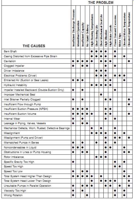
TBL. 1 Common Failure Modes of Centrifugal Pumps
THE CAUSES:
Bent Shaft Casing Distorted from Excessive Pipe Strain Cavitation Clogged Impeller Driver Imbalance Electrical Problems (Driver) Entrained Air (Suction or Seal Leaks) Hydraulic Instability Impeller Installed Backward (Double-Suction Only) Improper Mechanical Seal Inlet Strainer Partially Clogged Insufficient Flow through Pump Insufficient Suction Pressure (NPSH) Insufficient Suction Volume Internal Wear Leakage in Piping, Valves, Vessels Mechanical Defects, Worn, Rusted, Defective Bearings Misalignment Mis-alignment (Pump and Driver) Mismatched Pumps in Series Non-condensables in Liquid Obstructions in Lines or Pump Housing Rotor Imbalance Specific Gravity Too High Speed Too High Speed Too Low Total System Head Higher Than Design Total System Head Lower Than Design Unsuitable Pumps in Parallel Operation Viscosity Too High Wrong Rotation
THE PROBLEM:
Insufficient Discharge Pressure Intermittent Operation Insufficient Capacity No Liquid Delivery High Bearing Temperatures Short Bearing Life Short Mechanical Seal Life High Vibration High Noise Levels Power Demand Excessive Motor Trips Elevated Motor Temperature Elevated Liquid Temperature
========
Cavitation:
Cavitation in a centrifugal pump, which has a significant, negative effect on performance, is the most common failure mode. Cavitation not only degrades a pump's performance but also greatly accelerates the wear rate of its internal components. There are three causes of cavitation in centrifugal pumps: change of phase, entrained air or gas, and turbulent flow.
Change of Phase. The formation or collapse of vapor bubbles in either the suction piping or inside the pump is one cause of cavitation. This failure mode normally occurs in applications, such as boiler feed, where the incoming liquid is at a temperature near its saturation point. In this situation, a slight change in suction pressure can cause the liquid to flash into its gaseous state. In the boiler-feed example, the water flashes into steam. The reverse process also can occur. A slight increase in suction pressure can force the entrained vapor to change phase to a liquid.
Cavitation caused by phase change seriously damages the pump's internal components. Visual evidence of operation with phase-change cavitation is an impeller surface finish like an orange peel. Prolonged operation causes small pits or holes on both the impeller shroud and vanes.
Entrained Air/Gas. Pumps are designed to handle gas-free liquids. If a centrifugal pump's suction supply contains any appreciable quantity of gas, the pump will cavitate. In the example of cavitation caused by entrainment, the liquid is reasonably stable, unlike with the change of phase described in the preceding section. Nevertheless, the entrained gas has a negative effect on pump performance. Although this form of cavitation does not seriously affect the pump's internal components, it severely restricts its output and efficiency.
The primary causes of cavitation resulting from entrained gas include two-phase suction supply, inadequate available net positive suction head (NPSHA), and leakage in the suction-supply system. In some applications, the incoming liquid may contain moderate to high concentrations of air or gas. This may result from aeration or mixing of the liquid before reaching the pump or inadequate liquid levels in the supply reservoir. Regardless of the reason, the pump is forced to handle two-phase flow, which was not intended in its design.
Turbulent Flow. The effects of turbulent flow (not a true form of cavitation) on pump performance are almost identical to those described for entrained air or gas in the preceding section. Pumps are not designed to handle incoming liquids that don’t have stable, laminar flow patterns. Therefore, if the flow is unstable, or turbulent, the symptoms are the same as for cavitation.
Symptoms:
Noise (e.g., like a can of marbles being shaken) is one indication that a centrifugal pump is cavitating. Other indications are fluctuations of the pressure gauges, flowrate, and motor current, as well as changes in the vibration profile.
How to Eliminate:
Several design or operational changes may be necessary to stop centrifugal pump cavitation. Increasing the available net positive suction head (NPSHA) above that required (NPSHR) is one way to stop it. The NPSH required to prevent cavitation is determined through testing by the pump manufacturer. It depends on several factors, including type of impeller inlet, impeller design, impeller rotational speed, pump flowrate, and the type of liquid being pumped. The manufacturer typically supplies curves of NPSHR as a function of flowrate for a particular liquid (usually water) in the pump's manual.
One way to increase the NPSHA is to increase the pump's suction pressure. If a pump is fed from an enclosed tank, either raising the level of the liquid in the tank or increasing the pressure in the gas space above the liquid can increase suction pressure. It’s also possible to increase the NPSHA by decreasing the temperature of the liquid being pumped. This decreases the saturation pressure, which increases NPSHA.
If the head losses in the suction piping can be reduced, the NPSHA will be increased. Methods for reducing head losses include increasing the pipe diameter; reducing the number of elbows, valves, and fittings in the pipe; and decreasing the pipe length.
It also may be possible to stop cavitation by reducing the pump's NPSHR, which is not a constant for a given pump under all conditions. Typically, the NPSHR increases significantly as the pump's flowrate increases. Therefore, reducing the flowrate by throttling a discharge valve decreases NPSHR. In addition to flowrate, NPSHR depends on pump speed. The faster the pump's impeller rotates, the greater the NPSHR. There fore, if the speed of a variable-speed centrifugal pump is reduced, the NPSHR of the pump is decreased.
Variations in Total System Head:
Centrifugal pump performance follows its hydraulic curve (i.e., head versus flowrate).
Therefore, any variation in the total back-pressure of the system causes a change in the pump's flow or output. Because pumps are designed to operate at their best efficiency point (BEP), they become more and more unstable as they are forced to operate at any other point because of changes in total system pressure, or head (TSH). This instability has a direct impact on centrifugal pump performance, reliability, operating costs, and required maintenance.
Symptoms of Changed Conditions:
The symptoms of failure caused by variations in TSH include changes in motor speed and flowrate.
Motor Speed. The brake horsepower of the motor that drives a pump is load dependent. As the pump's operating point deviates from BEP, the amount of horsepower required also changes. This causes a change in the pump's rotating speed, which either increases or decreases depending on the amount of work the pump must perform.
Flowrate. The volume of liquid delivered by the pump varies with changes in TSH.
An increase in the total system back-pressure results in decreased flow, whereas a back-pressure reduction increases the pump's output.
Correcting Problems:
The best solution to problems caused by TSH variations is to prevent the variations.
Although it’s not possible to completely eliminate them, the operating practices for centrifugal pumps should limit operation to an acceptable range of system demand for flow and pressure. If system demand exceeds the pump's capabilities, it may be necessary to change the pump, the system requirements, or both. In many applications, the pump is either too small or too large. In these instances, it’s necessary to replace the pump with one that is properly sized.
For applications where the TSH is too low and the pump is operating in run-out condition (i.e., maximum flow and minimum discharge pressure), the system demand can be corrected by restricting the discharge flow of the pump. This approach, called false head, changes the system's head by partially closing a discharge valve to increase the back-pressure on the pump. Because the pump must follow it's hydraulic curve, this forces the pump's performance back toward its BEP.
When the TSH is too great, there are two options: replace the pump or lower the system's back-pressure by eliminating line resistance caused by elbows, extra valves, and so on.
Positive-Displacement Pumps
Positive-displacement pumps are more tolerant to variations in system demands and pressures than are centrifugal pumps; however, they are still subject to a variety of common failure modes caused directly or indirectly by the process.
Rotary-Type:
Rotary-type positive-displacement pumps share many common failure modes with centrifugal pumps. Both types of pumps are subject to process-induced failures caused by demands that exceed the pump's capabilities. Process-induced failures also are caused by operating methods that result in either radical changes in their operating envelope or instability in the process system.
TBL. 2 lists common failure modes for rotary-type positive-displacement pumps.
The most common failure modes of these pumps are generally attributed to problems with the suction supply. They must have a constant volume of clean liquid in order to function properly.
======
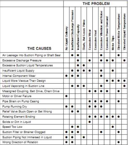
TBL. 2 Common Failure Modes of Rotary-Type, Positive-Displacement Pumps
THE PROBLEM---No Liquid Delivery Insufficient Discharge Pressure Insufficient Capacity Starts, But Loses Prime Excessive Wear Excessive Heat Excessive Vibration and Noise Excessive Power Demand Motor Trips Elevated Motor Temperature Elevated Liquid Temperature
THE CAUSES---Air Leakage into Suction Piping or Shaft Seal Excessive Discharge Pressure Excessive Suction Liquid Temperatures Insufficient Liquid Supply Internal Component Wear Liquid More Viscous Than Design Liquid Vaporizing in Suction Line Misaligned Coupling, Belt Drive, Chain Drive Motor or Driver Failure Pipe Strain on Pump Casing Pump Running Dry Relief Valve Stuck Open or Set Wrong Rotating Element Binding Solids or Dirt in Liquid Speed Too Low Suction Filter or Strainer Clogged Suction Piping Not Immersed in Liquid Wrong Direction of Rotation Source: Integrated Systems, Inc.
===
Reciprocating:
TBL. 3 lists the common failure modes for reciprocating positive-displacement pumps. Reciprocating pumps can generally withstand more abuse and variations in system demand than any other type; however, they must have a consistent supply of relatively clean liquid in order to function properly.
The weak links in the reciprocating pump's design are the inlet and discharge valves used to control pumping action. These valves are the most common source of failure.
In most cases, valve failure is caused by fatigue. The only positive way to prevent or minimize these failures is to ensure that proper maintenance is performed regularly on these components. It’s important to follow the manufacturer's recommendations for valve maintenance and replacement.
===
TBL. 3 Common Failure Modes of Reciprocating Positive-Displacement Pumps
THE PROBLEM---No Liquid Delivery Insufficient Capacity Short Packing Life Excessive Wear Liquid End Excessive Wear Power End Excessive Heat Power End Excessive Vibration and Noise Persistent Knocking Motor Trips:
THE CAUSES---Abrasives or Corrosives in Liquid Broken Valve Springs Cylinders Not Filling Drive-Train Problems Excessive Suction Lift Gear Drive Problem Improper Packing Selection Inadequate Lubrication Liquid Entry into Power End of Pump Loose Cross-Head Pin or Crank Pin Loose Piston or Rod Low Volumetric Efficiency Misalignment of Rod or Packing Non-Condensables (Air) in Liquid Not Enough Suction Pressure Obstructions in Lines One or More Cylinders Not Operating Other Mechanical Problems: Wear, Rusted, etc.
Overloading Pump Speed Incorrect Pump Valve(s) Stuck Open Relief or Bypass Valve(s) Leaking Scored Rod or Plunger Supply Tank Empty Worn Cross-Head or Guides Worn Valves, Seats, Liners, Rods, or Plungers
====
Because of the close tolerances between the pistons and the cylinder walls, reciprocating pumps cannot tolerate contaminated liquid in their suction-supply system.
Many of the failure modes associated with this type of pump are caused by contamination (e.g., dirt, grit, and other solids) that enters the suction-side of the pump. This problem can be prevented by using well-maintained inlet strainers or filters.
FANS, BLOWERS, AND FLUIDIZERS
===
TBL. 4 Common Failure Modes of Centrifugal Fans
THE PROBLEM---Insufficient Discharge Pressure Intermittent Operation Insufficient Capacity Overheated Bearings Short Bearing Life Overload on Driver High Vibration High Noise Levels Power Demand Excessive Motor Trips
THE CAUSES---Abnormal End Thrust Aerodynamic Instability Air Leaks in System Bearings Improperly Lubricated Bent Shaft Broken or Loose Bolts or Setscrews Damaged Motor Damaged Wheel Dampers or Variable-Inlet Not Properly Adjusted Dirt in Bearings Excessive Belt Tension External Radiated Heat Fan Delivering More Than Rated Capacity Fan Wheel or Driver Imbalanced Foreign Material in Fan Causing Imbalance (Plate-Out) Incorrect Direction of Rotation Insufficient Belt Tension Loose Dampers or Variable-Inlet Vanes Misalignment of Bearings, Coupling, Wheel, or Belts Motor Improperly Wired Packing Too Tight or Defective Stuffing Box Poor Fan Inlet or Outlet Conditions Specific Gravity or Density Above Design Speed Too High Speed Too Low Too Much Grease in Ball Bearings Total System Head Greater Than Design Total System Head Less Than Design Unstable Foundation Vibration Transmitted to Fan from Outside Sources Wheel Binding on Fan Housing Wheel Mounted Backward on Shaft Worn Bearings Worn Coupling 120-Cycle Magnetic Hum
===
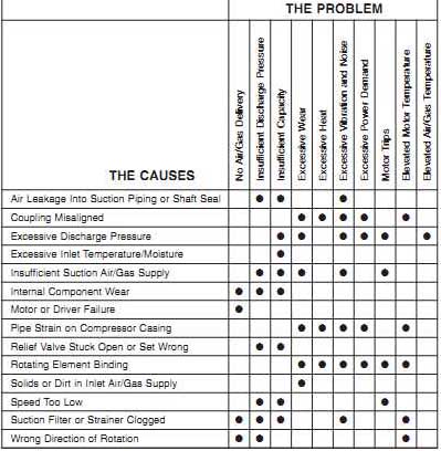
TBL. 5 Common Failure Modes of Blowers and Fluidizers
THE CAUSES---No Air/Gas Delivery Insufficient Discharge Pressure Insufficient Capacity Excessive Wear Excessive Heat Excessive Vibration and Noise Excessive Power Demand Motor Trips Elevated Motor Temperature Elevated Air/Gas Temperature
THE PROBLEM---Air Leakage into Suction Piping or Shaft Seal Coupling Misaligned Excessive Discharge Pressure Excessive Inlet Temperature/Moisture Insufficient Suction Air/Gas Supply Internal Component Wear Motor or Driver Failure Pipe Strain on Blower Casing Relief Valve Stuck Open or Set Wrong Rotating Element Binding Solids or Dirt in Inlet Air/Gas Supply Speed Too Low Suction Filter or Strainer Clogged Wrong Direction of Rotation
===
Tables 4 and 5 list the common failure modes for fans, blowers, and fluidizers. Typical problems with these devices include output below rating, vibration and noise, and overloaded driver bearings.
Centrifugal Fans
Centrifugal fans are extremely sensitive to variations in either suction or discharge conditions. In addition to variations in ambient conditions (e.g., temperature, humidity), control variables can have a direct effect on fan performance and reliability.
Most of the problems that limit fan performance and reliability are either directly or indirectly caused by improper application, installation, operation, or maintenance; however, the majority is caused by misapplication or poor operating practices. TBL. 4 lists failure modes of centrifugal fans and their causes. Some of the more common failures are aerodynamic instability, plate-out, speed changes, and lateral flexibility.
Aerodynamic Instability:
Generally, the control range of centrifugal fans is about 15 percent above and 15 percent below its BEP. When fans are operated outside of this range, they tend to become progressively unstable, which causes the fan's rotor assembly and shaft to deflect from their true centerline. This deflection increases the vibration energy of the fan and accelerates the wear rate of bearings and other drive-train components.
Plate-Out:
Dirt, moisture, and other contaminates tend to adhere to the fan's rotating element.
This buildup, called plate-out, increases the mass of the rotor assembly and decreases its critical speed, the point where the phenomenon referred to as resonance occurs.
This occurs because the additional mass affects the rotor's natural frequency. Even if the fan's speed does not change, the change in natural frequency may cause its critical speed (note that machines may have more than one) to coincide with the actual rotor speed. If this occurs, the fan will resonate, or experience severe vibration, and may catastrophically fail. The symptoms of plate-out are often confused with those of mechanical imbalance because both dramatically increase the vibration associated with the fan's running speed.
The problem of plate-out can be resolved by regularly cleaning the fan's rotating element and internal components. Removal of buildup lowers the rotor's mass and returns its natural frequency to the initial, or design, point. In extremely dirty or dusty environments, it may be advisable to install an automatic cleaning system that uses high-pressure air or water to periodically remove any buildup that occurs.
Speed Changes:
In applications where a measurable fan-speed change can occur (i.e., V-belt or variable-speed drives), care must be taken to ensure that the selected speed does not coincide with any of the fan's critical speeds. For general-purpose fans, the actual running speed is designed to be between 10 and 15 percent below the first critical speed of the rotating element. If the sheave ratio of a V-belt drive or the actual running speed is increased above the design value, it may coincide with a critical speed.
Some fans are designed to operate between critical speeds. In these applications, the fan must transition through the first critical point to reach its operating speed.
These transitions must be made as quickly as possible to prevent damage. If the fan's speed remains at or near the critical speed for any extended period, serious damage can occur.
Lateral Flexibility:
By design, the structural support of most general-purpose fans lacks the mass and rigidity needed to prevent flexing of the fan's housing and rotating assembly.
This problem is more pronounced in the horizontal plane, but also is present in the vertical direction. If support-structure flexing is found to be the root-cause or a major contributing factor to the problem, it can be corrected by increasing the stiffness and/or mass of the structure; however, don’t fill the structure with concrete. As it dries, concrete pulls away from the structure and does little to improve its rigidity.
Blowers or Positive-Displacement Fans
Blowers, or positive-displacement fans, have the same common failure modes as rotary pumps and compressors. TBL. 5 (see also Tables 10-2 and 10-9) lists the failure modes that most often affect blowers and fluidizers. In particular, blower failures occur because of process instability, caused by start/stop operation and demand variations, and mechanical failures caused by close tolerances.
Process Instability:
Blowers are very sensitive to variations in their operating envelope. As little as a one psig change in downstream pressure can cause the blower to become extremely unstable. The probability of catastrophic failure or severe damage to blower components increases in direct proportion to the amount and speed of the variation in demand or downstream pressure.
Start/Stop Operation. The transients caused by frequent start/stop operation also have a negative effect on blower reliability. Conversely, blowers that operate constantly in a stable environment rarely exhibit problems. The major reason is the severe axial thrusting caused by the frequent variations in suction or discharge pressure caused by the start/stop operation.
Demand Variations. Variations in pressure and volume demands have a serious impact on blower reliability. Because blowers are positive-displacement devices, they generate a constant volume and a variable pressure that depends on the downstream system's back-pressure. If demand decreases, the blower's discharge pressure continues to increase until (1) a downstream component fails and reduces the back-pressure, or (2) the brake horsepower required to drive the blower is greater than the motor's locked rotor rating. Either of these outcomes will result in failure of the blower system.
The former may result in a reportable release, whereas the latter will cause the motor to trip or burn out.
Frequent variations in demand greatly accelerate the wear rate of the thrust bearings in the blower. This can be directly attributed to the constant, instantaneous axial thrusting caused by variations in the discharge pressure required by the downstream system.
Mechanical Failures:
Because of the extremely close clearances that must exist within the blower, the potential for serious mechanical damage or catastrophic failure is higher than with other rotating machinery. The primary failure points include thrust bearings, timing gears, and rotor assemblies.
In many cases, these mechanical failures are caused by the instability discussed in the preceding sections, but poor maintenance practices are another major cause. See the troubleshooting guide in TBL. 9 for rotary-type, positive-displacement compressors for more information.
CONVEYORS
Conveyor failure modes vary depending on the type of system. Two common types of conveyor systems used in chemical plants are pneumatic and chain-type mechanical.
Pneumatic
TBL. 6 lists common failure modes associated with pneumatic-conveyor systems; however, most common problems can be attributed to either conveyor piping plugging or problems with the prime mover (i.e., fan or fluidizer). For a centrifugal fan troubleshooting guide, refer to TBL. 4. For fluidizer and blower guides, refer to TBL. 5.
Chain-Type Mechanical
The Hefler-type chain conveyor is a common type of mechanical conveyor used in integrated chemical plants. TBL. 7 provides the more common failure modes of this type of conveyor. Most of the failure modes defined in the table can be directly attributed to operating practices, changes in incoming product quality (i.e., density or contamination), or maintenance practices.
COMPRESSORS
Compressors can be divided into three classifications: centrifugal, rotary, and reciprocating. This section identifies the common failure modes for each.
===
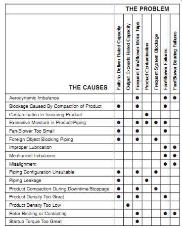
TBL. 6 Common Failure Modes of Pneumatic Conveyors
THE PROBLEM
Fails to Deliver Rated Capacity Output Exceeds Rated Capacity Frequent Fan/Blower Motor Trips Product Contamination Frequent System Blockage Fan/Blower Failures Fan/Blower Bearing Failures THE CAUSES
Aerodynamic Imbalance Blockage Caused By Compaction of Product Contamination in Incoming Product Excessive Moisture in Product/Piping Fan/Blower Too Small Foreign Object Blocking Piping Improper Lubrication Mechanical Imbalance Misalignment Piping Configuration Unsuitable Piping Leakage Product Compaction During Downtime/Stoppage Product Density Too Great Product Density Too Low Rotor Binding or Contacting Startup Torque Too Great
---
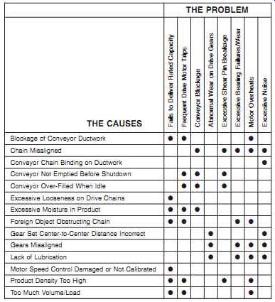
TBL. 7 Common Failure Modes of Hefler-Type Chain Conveyors
THE PROBLEM
Fails to Deliver Rated Capacity Frequent Drive Motor Trips Conveyor Blockage Abnormal Wear on Drive Gears Excessive Shear Pin Breakage Excessive Bearing Failures/Wear Motor Overheats Excessive Noise
THE CAUSES
Blockage of Conveyor Ductwork Chain Misaligned Conveyor Chain Binding on Ductwork Conveyor Not Emptied Before Shutdown Conveyor Over-Filled When Idle Excessive Looseness on Drive Chains Excessive Moisture in Product Foreign Object Obstructing Chain Gear Set Center-to-Center Distance Incorrect Gears Misaligned Lack of Lubrication Motor Speed Control Damaged or Not Calibrated Product Density Too High Too Much Volume/Load
---
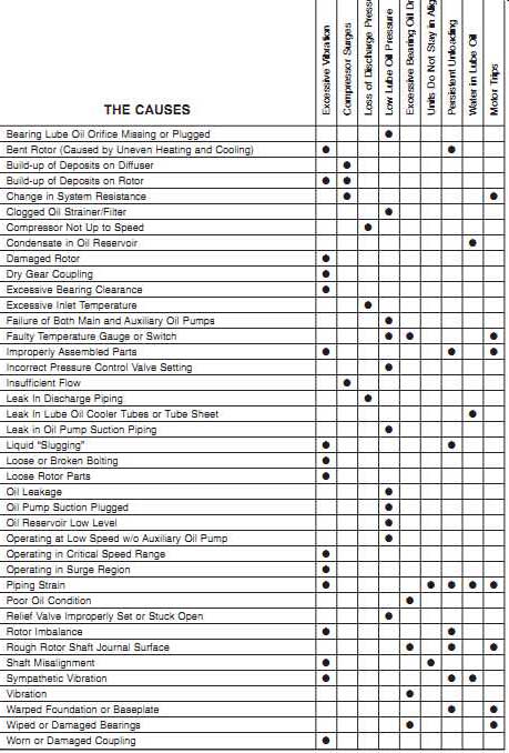
TBL. 8 Common Failure Modes of Centrifugal Compressors
THE PROBLEM
Excessive Vibration Compressor Surges Loss of Discharge Pressure Low Lube Oil Pressure Excessive Bearing Oil Drain Temp.
Units Do Not Stay in Alignment Persistent Unloading Water in Lube Oil Motor Trips
THE CAUSES
Bearing Lube Oil Orifice Missing or Plugged Bent Rotor (Caused by Uneven Heating and Cooling) Build-up of Deposits on Diffuser Build-up of Deposits on Rotor Change in System Resistance Clogged Oil Strainer/Filter Compressor Not Up to Speed Condensate in Oil Reservoir Damaged Rotor Dry Gear Coupling Excessive Bearing Clearance Excessive Inlet Temperature Failure of Both Main and Auxiliary Oil Pumps Faulty Temperature Gauge or Switch Improperly Assembled Parts Incorrect Pressure Control Valve Setting Insufficient Flow Leak In Discharge Piping Leak In Lube Oil Cooler Tubes or Tube Sheet Leak in Oil Pump Suction Piping Liquid "Slugging" Loose or Broken Bolting Loose Rotor Parts Oil Leakage Oil Pump Suction Plugged Oil Reservoir Low Level Operating at Low Speed w/o Auxiliary Oil Pump Operating in Critical Speed Range Operating in Surge Region Piping Strain Poor Oil Condition Relief Valve Improperly Set or Stuck Open Rotor Imbalance Rough Rotor Shaft Journal Surface Shaft Misalignment Sympathetic Vibration; Vibration Warped Foundation or Baseplate Wiped or Damaged Bearings Worn or Damaged Coupling
-----
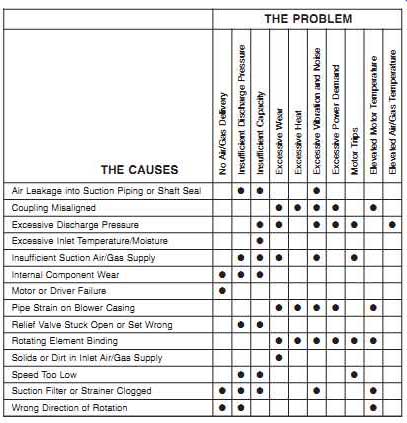
TBL. 9 Common Failure Modes of Rotary-Type, Positive-Displacement Compressors
THE PROBLEM
No Air/Gas Delivery Insufficient Discharge Pressure Insufficient Capacity Excessive Wear Excessive Heat Excessive Vibration and Noise Excessive Power Demand Motor Trips Elevated Motor Temperature Elevated Air/Gas Temperature
THE CAUSES
Air Leakage Into Suction Piping or Shaft Seal Coupling Misaligned Excessive Discharge Pressure Excessive Inlet Temperature/Moisture Insufficient Suction Air/Gas Supply Internal Component Wear Motor or Driver Failure Pipe Strain on Compressor Casing Relief Valve Stuck Open or Set Wrong Rotating Element Binding Solids or Dirt in Inlet Air/Gas Supply Speed Too Low Suction Filter or Strainer Clogged Wrong Direction of Rotation Source: Integrated Systems, Inc.
====
Centrifugal
The operating dynamics of centrifugal compressors are the same as for other centrifugal machine-trains. The dominant forces and vibration profiles are typically identical to pumps or fans; however, the effects of variable load and other process variables (e.g., temperatures, inlet/discharge pressure) are more pronounced than in other rotating machines. TBL. 8 identifies the common failure modes for centrifugal compressors.
Aerodynamic instability is the most common failure mode for centrifugal compressors. Variable demand and restrictions of the inlet airflow are common sources of this instability. Even slight variations can cause dramatic changes in the operating stability of the compressor.
Entrained liquids and solids can also affect operating life. When dirty air must be handled, open-type impellers should be used. An open design provides the ability to handle a moderate amount of dirt or other solids in the inlet air supply; however, inlet filters are recommended for all applications, and controlled liquid injection for cleaning and cooling should be considered during the design process.
Rotary-Type Positive Displacement
TBL. 9 lists the common failure modes of rotary-type positive-displacement compressors. This type of compressor can be grouped into two types: sliding vane and rotary screw.
Sliding Vane:
Sliding-vane compressors have the same failure modes as vane-type pumps. The dominant components in their vibration profile are running speed, vane-pass frequency, and bearing-rotation frequencies. In normal operation, the dominate energy is at the shaft's running speed. The other frequency components are at much lower energy levels. Common failures of this type of compressor occur with shaft seals, vanes, and bearings.
Shaft Seals. Leakage through the shaft's seals should be checked visually once a week or as part of every data acquisition route. Leakage may not be apparent from the outside of the gland. If the fluid is removed through a vent, the discharge should be con figured for easy inspection. Generally, more leakage than normal is the signal to replace a seal. Under good conditions, they have a normal life of 10,000 to 15,000 hours and should routinely be replaced when this service life has been reached.
Vanes. Vanes wear continuously on their outer edges and, to some degree, on the faces that slide in and out of the slots. The vane material is affected somewhat by prolonged heat, which causes gradual deterioration. Typical life expectancy of vanes in 100 psig service is about 16,000 hours of operation. For low-pressure applications, life may reach 32,000 hours.
Replacing vanes before they break is extremely important. Breakage during operation can severely damage the compressor, which requires a complete overhaul and realignment of heads and clearances.
Bearings. In normal service, bearings have a relatively long life. Replacement after about six years of operation is generally recommended. Bearing defects are usually displayed in the same manner in a vibration profile as for any rotating machine-train.
Inner- and outer-race defects are the dominant failure modes, but roller spin may also contribute to the failure.
Rotary Screw:
The most common reason for compressor failure or component damage is process instability. Rotary-screw compressors are designed to deliver a constant volume and pressure of air or gas. These units are extremely susceptible to any change in either inlet or discharge conditions. A slight variation in pressure, temperature, or volume can result in instantaneous failure. The following are used as indices of instability and potential problems: rotor mesh, axial movement, thrust bearings, and gear mesh.
Rotor Mesh. In normal operation, the vibration energy generated by male and female rotor meshing is very low. As the process becomes unstable, the energy caused by the rotor-meshing frequency increases, with both the amplitude of the meshing frequency and the width of the peak increasing. In addition, the noise floor surrounding the meshing frequency becomes more pronounced. This white noise is similar to that observed in a cavitating pump or unstable fan.
Axial Movement. The normal tendency of the rotors and helical timing gears is to generate axial shaft movement, or thrusting; however, the extremely tight clearances between the male and female rotors don’t tolerate any excessive axial movement and, therefore, axial movement should be a primary monitoring parameter.
Axial measurements are needed from both rotor assemblies. If the vibration amplitude of these measurements increases at all, it’s highly probable that the compressor will fail.
Thrust Bearings. Although process instability can affect both fixed and float bearings, thrust bearings are more likely to show early degradation as a result of process instability or abnormal compressor dynamics. Therefore, these bearings should be monitored closely, and any degradation or hint of excessive axial clearance should be corrected immediately.
Gear-Mesh. The gear-mesh vibration profile also indicates prolonged compressor instability. Deflection of the rotor shafts changes the wear pattern on the helical gear sets. This change in pattern increases the backlash in the gear mesh, results in higher vibration levels, and increases thrusting.
========
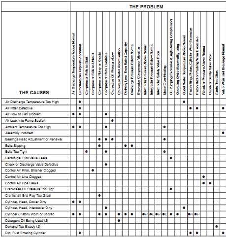
TBL. 10a Common Failure Modes of Reciprocating Compressors
THE PROBLEM
Air Discharge Temperature Above Normal Carbonaceous Deposits Abnormal Compressor Fails to Start Compressor Fails to Unload Compressor Noisy or Knocks Compressor Parts Overheat Crankcase Oil Pressure Low Crankcase Water Accumulation Delivery Less Than Rated Capacity Discharge Pressure Below Normal Excessive Compressor Vibration Interceder Pressure Above Normal Interceder Pressure Below Normal Intercooler Safety Valve Pops Motor Over-Heating Oil Pumping Excessive (Single-Acting Compressor) Operating Cycle Abnormality Long Outlet Water Temperature Above Normal Piston Ring, Piston, Cylinder Wear Excessive Piston Rod or Packing Wear Excessive Receiver Pressure Above Normal Receiver Safety Valve Pops Starts Too Often Valve Wear and Breakage Normal
THE CAUSES
Air Discharge Temperature Too High Air Fitter Defective Air Flow to Fan Blocked Air Leak into Pump Suction Ambient Temperature Too High Assembly Incorrect Bearings Need Adjustment or Renewal Belts Slipping Belts Too Tight Centrifugal Pilot Valve Leaks Check or Discharge Valve Defective Control Air Filter, Strainer Clogged Control Air Line Clogged Control Air Pipe Leaks Crankcase Oil Pressure Too High Crankshaft End Play Too Great Cylinder, Head, Cooler Dirty Cylinder, Head, Intercooler Dirty Cylinder (Piston) Worn or Scored Detergent Oil Being Used (3) Demand Too Steady (2) Dirt, Rust Entering Cylinder
-----------
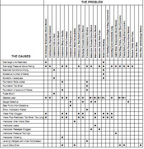
TBL. 10b Common Failure Modes of Reciprocating Compressors
THE PROBLEM
Air Discharge Temperature Above Normal Carbonaceous Deposits Abnormal Compressor Fails to Start Compressor Fails to Unload Compressor Noisy or Knocks Compressor Parts Overheat Crankcase Oil Pressure Low Crankcase Water Accumulation Delivery Less Than Rated Capacity Discharge Pressure Below Normal Excessive Compressor Vibration Intercooler Pressure Above Normal Intercooler Pressure Below Normal Intercooler Safety Valve Pops Motor Over-Heating Oil Pumping Excessive (Single-Acting Compressor) Operating Cycle Abnormally Long Outlet Water Temperature Above Normal Piston Ring, Piston, Cylinder Wear Excessive Piston Rod or Packing Wear Excessive Receiver Pressure Above Normal Receiver Safety Valve Pops Starts Too Often Valve Wear and Breakage Normal
THE CAUSES
Discharge Line Restricted Discharge Pressure Above Rating Electrical Conditions Wrong Excessive Number of Starts Excitation Inadequate Foundation Bolts Loose Foundation Too Small Foundation Uneven-Unit Rocks Fuses Blown Gaskets Leak Gauge Defective Gear Pump Worn/Defective Grout, Improperly Placed Intake Filter Clogged Intake Pipe Restricted, Too Small, Too Long Intercooler, Drain More Often Intercooler Leaks Intercooler Passages Clogged Intercooler Pressure Too High Intercooler Vibrating Leveling Wedges Left Under Compressor Liquid Carry-Over
----------
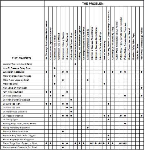
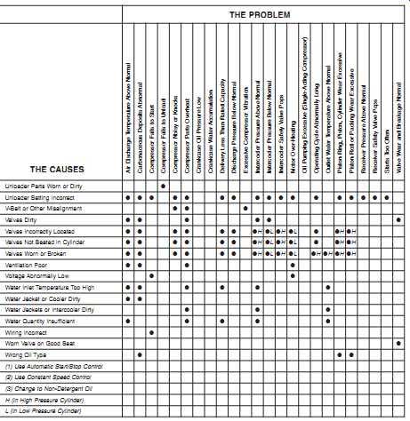
TBL. 10c Common Failure Modes of Reciprocating Compressors
THE PROBLEM
Air Discharge Temperature Above Normal Carbonaceous Deposits Abnormal Compressor Fails to Start Compressor Fails to Unload; Compressor Noisy or Knocks Compressor Parts Overheat Crankcase Oil Pressure Low Crankcase Water Accumulation Delivery Less Than Rated Capacity Discharge Pressure Below Normal Excessive Compressor Vibration Intercooler Pressure Above Normal Intercooler Pressure Below Normal Intercooler Safety Valve Pops Motor Over-Heating Oil Pumping Excessive (Single-Acting Compressor) Operating Cycle Abnormality Long Outlet Water Temperature Above Normal Piston Ring, Piston, Cylinder Wear Excessive Piston Rod or Packing Wear Excessive Receiver Pressure Above Normal Receiver Safety Valve Pops Starts Too Often Valve Wear and Breakage Normal
THE CAUSES
Location Too Humid and Damp Low Oil Pressure Relay Open Lubrication Inadequate Motor Overload Relay Tripped Motor Rotor Loose on Shaft Motor Too Small New Valve on Worn Seat
"Off" Time Insufficient Oil Feed Excessive Oil Filter or Strainer Clogged Oil Level Too High Oil Level Too Low Oil Relief Valve Defective Oil Viscosity Incorrect Oil Wrong Type Packing Rings Worn, Stuck, Broken Piping Improperly Supported Piston or Piston Nut Loose Piston or Ring Drain Hole Clogged Piston Ring Gaps Not Staggered Piston Rings Worn, Broken, or Stuck Piston-to-Head Clearance Too Small
=========
Reciprocating Positive Displacement
Reciprocating compressors have a history of chronic failures that include valves, lubrication system, pulsation, and imbalance. TBL. 10a to e identifies common failure modes and causes for this type of compressor.
Like all reciprocating machines, reciprocating compressors normally generate higher levels of vibration than centrifugal machines. In part, the increased level of vibration is caused by the impact as each piston reaches top dead-center and bottom dead-center of its stroke. The energy levels are also influenced by the unbalanced forces generated by non-opposed pistons and looseness in the piston rods, wrist pins, and journals of the compressor. In most cases, the dominant vibration frequency is the second harmonic (2X) of the main crankshaft's rotating speed. Again, this results from the impact that occurs when each piston changes directions (i.e., two impacts occur during one complete crankshaft rotation).
Valves:
Valve failure is the dominant failure mode for reciprocating compressors. Because of their high cyclic rate, which exceeds 80 million cycles per year, inlet and discharge valves tend to work hard and crack.
Lubrication System:
Poor maintenance of lubrication system components, such as filters and strainers, typically causes premature failure. Such maintenance is crucial to reciprocating compressors because they rely on the lubrication system to provide a uniform oil film between closely fitting parts (e.g., piston rings and the cylinder wall). Partial or complete failure of the lube system results in catastrophic failure of the compressor.
Pulsation:
Reciprocating compressors generate pulses of compressed air or gas that are discharged into the piping that transports the air or gas to its point(s) of use. This pulsation often generates resonance in the piping system, and pulse impact (i.e., standing waves) can severely damage other machinery connected to the compressed-air system.
Although this behavior does not cause the compressor to fail, it must be prevented to protect other plant equipment. Note, however, that most compressed-air systems don’t use pulsation dampers.
=============
TBL. 10d Common Failure Modes of Reciprocating Compressors
THE PROBLEM:
Air Discharge Temperature Above Normal Carbonaceous Deposits Abnormal Compressor Fails to Start Compressor Fails to Unload Compressor Noisy or Knocks Compressor Parts Overheat Crankcase Oil Pressure Low Crankcase Water Accumulation Delivery Less Than Rated Capacity Discharge Pressure Below Normal Excessive Compressor Vibration Intercooler Pressure Above Normal Intercooler Pressure Below Normal Intercooler Safety Valve Pops Motor Over-Heating Oil Pumping Excessive (Single-Acting Compressor) Operating Cycle Abnormally Long Outlet Water Temperature Above Normal Piston Ring, Piston, Cylinder Wear Excessive Piston Rod or Packing Wear Excessive Receiver Pressure Above Normal Receiver Safety Valve Pops Starts Too Often Valve Wear and Breakage Normal
THE CAUSES:
Pulley or Flywheel Loose Receiver, Drain More Often Receiver Too Small Regulation Piping Clogged Resonant Pulsation (Inlet or Discharge) Rod Packing Leaks Rod Packing Too Tight Rod Scored, Pitted, Worn Rotation Wrong Runs Too Little (2) Safety Valve Defective Safety Valve Leeks Safety Valve Set Too Low Speed Demands Exceed Rating Speed Lower Than Rating Speed Too High Springs Broken System Demand Exceeds Rating System Leakage Excessive Tank Ringing Noise Unloader Running Time Too Long (1) Unloader or Control Defective
============
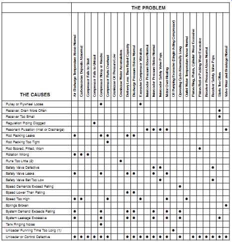
TBL. 10e Common Failure Modes of Reciprocating Compressors
THE PROBLEM:
Air Discharge Temperature Above Normal Carbonaceous Deposits Abnormal Compressor Fails to Start Compressor Fails to Unload Compressor Noisy or Knocks Compressor Parts Overheat Crankcase Oil Pressure Low Crankcase Water Accumulation Delivery Less Than Rated Capacity Discharge Pressure Below Normal Excessive Compressor Vibration Intercooler Pressure Above Normal Intercooler Pressure Below Normal Intercooler Safety Valve Pops Motor Over-Heating Oil Pumping Excessive (Single-Acting Compressor) Operating Cycle Abnormally Long Outlet Water Temperature Above Normal Piston Ring, Piston, Cylinder Wear Excessive Piston Rod or Packing Wear Excessive Receiver Pressure Above Normal Receiver Safety Valve Pops Starts Too Often Valve Wear and Breakage Normal
THE CAUSES:
Unloader Parts Worn or Dirty Unloader Setting Incorrect V-Belt or Other Misalignment Valves Dirty Valves Incorrectly Located Valves Not Seated in Cylinder Valves Worn or Broken Ventilation Poor Voltage Abnormally Low Water Inlet Temperature Too High Water Jacket or Cooler Dirty Water Jackets or Intercooler Dirty Water Quantity Insufficient Wiring Incorrect Worn Valve on Good Seat Wrong Oil Type (1) Use Automatic Start/Stop Control (2) Use Constant Speed Control (3) Change to Non-Detergent Oil H (in High Pressure Cylinder) L (in Low Pressure Cylinder)
=========
Each time the compressor discharges compressed air, the air tends to act like a compression spring. Because it rapidly expands to fill the discharge piping's available volume, the pulse of high-pressure air can cause serious damage. The pulsation wave length, l, from a compressor with a double-acting piston design can be determined …
Where:
l = Wavelength, feet
a = Speed of sound = 1,135 feet/second
n = Compressor speed, revolutions/minute
For a double-acting piston design, a compressor running at 1,200 revolutions per minute (rpm) will generate a standing wave of 28.4 feet. In other words, a shock load equivalent to the discharge pressure will be transmitted to any piping or machine connected to the discharge piping and located within 28 feet of the compressor. Note that, for a single-acting cylinder, the wavelength will be twice as long.
Imbalance:
Compressor inertial forces may have two effects on the operating dynamics of a reciprocating compressor, affecting its balance characteristics. The first effect is a force in the direction of the piston movement, which is displayed as impacts in a vibration profile as the piston reaches top and bottom dead-center of its stroke. The second effect is a couple, or moment, caused by an offset between the axes of two or more pistons on a common crankshaft. The interrelationship and magnitude of these two effects depend on such factors as number of cranks, longitudinal and angular arrangement, cylinder arrangement, and amount of counterbalancing possible. Two significant vibration periods result, the primary at the compressor's rotation speed (X) and the secondary at 2X.
Although the forces developed are sinusoidal, only the maximum (i.e., the amplitude) is considered in the analysis. FIG. 1 shows relative values of the inertial forces for various compressor arrangements.
MIXERS AND AGITATORS
TBL. 11 identifies common failure modes and their causes for mixers and agitators. Most of the problems that affect performance and reliability are caused by improper installation or variations in the product's physical properties.
Proper installation of mixers and agitators is critical. The physical location of the vanes or propellers within the vessel is the dominant factor to consider. If the vanes are set too close to the side, corner, or bottom of the vessel, a stagnant zone will develop that causes both loss of mixing quality and premature damage to the equipment. If the vanes are set too close to the liquid level, vortexing can develop. This causes a loss of efficiency and accelerated component wear.
TBL. 11 Common Failure Modes of Mixers And Agitators
THE PROBLEM
Surface Vortex Visible Incomplete Mixing of Product Excessive Vibration Excessive Wear Motor Overheats Excessive Power Demand Excessive Bearing Failures
THE CAUSES
Abrasives in Product Mixer/Agitator Setting Too Close to Side or Corner Mixer/Agitator Setting Too High Mixer/Agitator Setting Too Low Mixer/Agitator Shaft Too Long Product Temperature Too Low Rotating Element Imbalanced or Damaged Speed Too High Speed Too Low Viscosity/Specific Gravity Too High Wrong Direction of Rotation
Variations in the product's physical properties, such as viscosity, also cause loss of mixing efficiency and premature wear of mixer components. Although the initial selection of the mixer or agitator may have addressed the full range of physical properties expected to be encountered, applications sometimes change. Such a change may result in the use of improper equipment for a particular application. (cont. part 2)