AMAZON multi-meters discounts AMAZON oscilloscope discounts
Compression Basics
Gases are fluids that take the shape of their container and are highly compressible when compared to liquids. Gases can be either pure or a composition of different gases with varying molecular weights.
Given two equal volumes of gas at identical pressures and temperatures, the volume containing gases with a higher average molecular weight will have a higher density, which means it will have a greater mass per unit volume. We must know the volume, pressure, temperature, and composition of a gas to fully define its nature and condition.
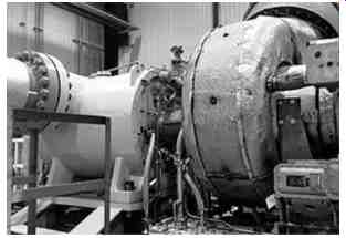
FIG. 1--Centrifugal compressor driven by a gas turbine
A compressor is a fluid handling machine that takes in gas at a lower density and pressure via a suction nozzle and compresses it, resulting in the gas having a higher density and pressure in the discharge nozzle. FIG. 2 demonstrates how compression works: It begins with a given starting volume of gas, as shown on the left in FIG. 2. The gas is squeezed into a smaller volume, as shown on the right. Notice that the starting volume of the gas has been reduced, while the number of molecules inside the container remains the same. A smaller volume with the same number of molecules means that density has increased. Compressors like centrifugal pumps have larger inlets than discharges making it easy to determine which is which.
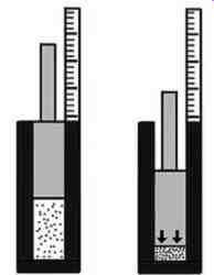
FIG. 2--During the gas compression process, a volume of gas is decreased
in order to increase i ts pressure as shown on the right.
The act of compression requires power, provided by drivers such as motors, steam turbines, and gas turbines, to push the molecules into a smaller volume. This, in turn, forces them closer together and pressure to increase. It is the higher pressure that pushes gas flow out of the compressor's discharge nozzle into the process. In addition to an increase in pressure, the act of compression causes the gas to heat up. The greater the level of compression, the higher the temperature increase you can expect.
Defining Gas Flow
One way that compressors are different than pumps is the way flow rates are expressed. Because liquids are essentially incompressible, there is no need to be concerned about the effect of pressure on the flow volume. 100 gallons per minute at 10 psi is essentially 100 gallons per minute at 500 psi.
The same cannot be said about gases. Gases are compressible and the density of a gas is highly dependent on its pressure and temperature. Gas flow is expressed in one of two ways: 1) standard cubic feet per unit time or 2) actual cubic feet per unit time.
Standard cubic feet per minute (SCFM) is the flow-rate of a gas corrected to standard temperature and pressure. Expressing gas flow in terms of standard conditions is handy because the value is independent of temperature and pressure. Standard conditions are 14.7 psi (absolute) and 60 degr. F. If we say we have 100 standard cubic feet of a gas it means that at 14.7 psia and 60-degr F we would expect to have 100 cubic feet of gas. In contrast, the term "actual cubic feet per minute" (ACFM) is used to express the volume of gas flowing anywhere in a system. If a system were moving a gas at exactly standard conditions, then ACFM would equal SCFM.
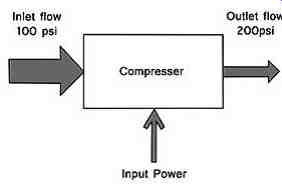
FIG. 3--Compressor Schematic
FIG. 3 shows a gas compressor changing a gas stream from 100 psi to 200 psi. The larger input arrow on the left is meant to show that the actual cubic feet per minute is larger than the actual cubic feet per minute at the outlet conditions shown by the smaller arrow on the right. Even though the actual cubic feet per minute value is smaller on the right, the standard cubic feet per minute is the same at the inlet and outlet conditions. The lesson to remember here is that you need to understand which measurement units of the flow you are dealing with when examining compressor performance.
Compressor Types
Compressors come in many different designs in order to handle a wide variety of process applications. The two most common compressor designs are positive displacement and dynamic (see FIG. 4). Positive displacement compressors include reciprocating (see FIG. 9) and rotary units (see FIG. 5). Positive displacement compressors work by continually forcing gas into a smaller and smaller volume, using either a piston or tight-fitting rotors, and then expelling the reduced volume of gas into a discharge passageway.
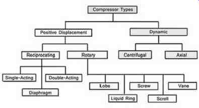
FIG. 4-Types of Compressors
FIG. 5 shows a cutaway view of a rotary screw compressor composed of two tightly fitting rotors inside a pressure containing housing. Positive displacement compressors generally deliver smaller gas volumes and much higher differential pressures than centrifugal or axial flow compressors. Piston compressors have a potential drawback of discharging the gas flow in pulses, which some processes may not be able to tolerate.
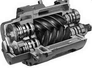
FIG. 5 Rotary Screw Compressor
Centrifugal compressors (see FIG. 6) and axial compressors fall in the category of dynamic compressors. This type works by accelerating gas with a rotating impeller or set of rotating blades and then converting the exiting high velocity gas stream into a higher pressure by decelerating the gas stream for the next compression stage. Like centrifugal pumps the inlet of a centrifugal compressor is larger than the outlet making it easy to identify the inlet and outline nozzles when tracing down the piping. The output of these compressors tends to be continuous, with very low pressure pulsations.
However, because dynamic compressors create pressure due to aerodynamic effects, they are susceptible to a flow condition called surging, which is characterized by violent, periodic flow reversals followed by the reestablishment of flow from suction to discharge. This is a serious operating condition that should be avoided. Surging can be detected either by a characteristic sound or, if equipped with proximity thrust probes, by the periodic back and forth axial movement of the rotor.
Centrifugal and reciprocating compressors are the type most often found in most petrochemical processes. Centrifugal compressors are used whenever high gas flows must be delivered at low to moderate differential pressures. Reciprocating compressors are used whenever low to medium gas flows must be delivered at high differential pressures.
For extremely high delivery pressure (up to 50,000 psi) applications, special reciprocating compressors, called hyper-compressors, are utilized. This SECTION will cover only conventional reciprocating compressors.
Multi-staging
Because the act of compression heats up the gas, there is a limit to how gas pressure much can be raised across any given compressor stage. Higher and higher pressures can be achieved by placing multiple stages of compression in series, that is, having the discharge of one stage of compression feed the intake of the next stage and so on (see FIG. 6). "Multi-staging" is the term used whenever multiple stages are used to meet the pressure requirements of a given application. Both reciprocating compressors and centrifugal compressors can be configured in multistage arrangements. If the temperature from one compression stage is predicted to get excessive, then inter-stage cooling is required to drop the gas temperature to a safe level before entering the next stage. Problems with inter-stage cooling systems can result in loss of flow, pressure capability, and in surging.
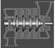
FIG. 6-Mutistage Centrifugal Compressor
Key Reliability Indicators
Some increase in the gas temperature is normal and expected. Many compressors have inter-coolers or after-coolers to handle this expected increase in temperature. However, whenever internal compressor issues, such as internal recycling, fouling, etc., are present, gas temperatures can rise well above what is expected. For this reason, compressor temperatures should constantly be closely monitored as a means of detecting internal problems. If high temperature conditions are not detected early, they can lead to the degradation of internal non-metallic elements, which in turn can escalate into a major failure. These high temperatures can also lead to compressor surges. It is best to set a temperature alarm on discharge of every compressor stage that is somewhat below the shutdown level. If the alarm sounds, you will have time to investigate the problem before the compressor either shuts down or you have to shut it down. Early intervention my prevent loss of run time productivity.
This is another case where knowing what "normal" is and knowing what the temperature was yesterday, last week, and last month is critical to detecting problems early.
Vibration is another major concern with and excellent indicator of mechanical condition of compressors. Vibration can be caused by imbalance, flow issues, foundation problems, internal looseness, etc. Make sure to monitor piping and skid vibration around reciprocating compressors as well the working components. When reporting a vibration problem, note any special conditions present when the abnormality occurs, such as the rotational speed or process conditions. These notations can be very helpful during troubleshooting later.
Centrifugal Compressors
Centrifugal compressors are a class of gas compressors that operates similarly to centrifugal pumps.
The gas enters the eye of an impeller and is accelerated outwardly toward a stationary diffuser that decelerates the gas stream and creates pressure. Typically, multiple stages of impeller/diffuser sets are required to generate the required differential pressure (see FIG. 7). The key components that make up centrifugal compressors are the rotor, rotor support bearings, end seals, diffusers between impeller stages, and a pressure casing. The rotor spins inside a pressure containing casing that houses the diffusers, which are designed to convert high velocity flow off of each impeller into higher and higher pressures, until flow reaches the discharge nozzle. Centrifugal compressor performance curves are similar to those of centrifugal pumps. They show that the pressure rise across a compressor increases as speed increases and drops as the flow through the compressor increases (see FIG. 8).
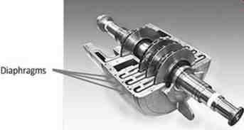
FIG. 7 A partially disassembled multistage centrifugal compressor showing
the rotor, casing, and flow diaphragms. Diaphragms guide the gas flow from
one compression stage to the next.
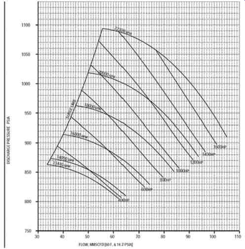
FIG. 8 Centrifugal Compressor Performance Curve
Troubleshooting Tips:
Here are some useful relationships to remember when dealing with centrifugal compressors:
• If the pressure on the discharge pressure gauge increases, the flow is likely decreasing.
Conversely, if the pressure on the discharge pressure gauge decreases, the flow is likely increasing if the suction pressure remains the same.
• If the compressor speed increases, the flow and discharge pressure will likely increase. The horsepower required by a compressor increases at higher speeds, which should be reflected by increasing amps or kilowatts if the compressor is motor driven. Conversely, if the compressor speed decreases, the flow and discharge pressure will likely decrease as with a turbine driven compressor. The horsepower required by the compressor at lower speed will decrease, which should be reflected by decreasing amps or kilowatts on motor driven compressors or decreasing steam input to the turbine.
• During start up and shutdown or upset conditions, the gas composition can change. If the molecular weight of the gas being compressed increases, the discharge pressure will increase and the required horsepower will also increase. Conversely, if the molecular weight of the gas being compressed decreases, the discharge pressure will decrease and the required horsepower will decrease.
• If the suction pressure increases, the discharge pressure will increase and the required horsepower will also increase. Conversely, if the suction pressure decreases, the discharge pressure will decrease and the required horsepower will decrease. All else being equal, a compressor is a differential pressure machine. Whatever goes in at one pressure will come out at a designed multiple pressure increase. If you raise the inlet pressure, the discharge pressure will also increase by the multiplier of the increase in the inlet pressure.
• Monitor the compressor balance line for temperature differences over time. A significant change can mean a balance piston seal problems, which can result in damaged thrust bearings.
These relationships will help to troubleshoot a problematic centrifugal compressor. When reporting a problem with a compressor, always list the symptoms that caught your attention, such as a low flow, high amps, leaking seals, vibration, not enough pressure, etc.
Centrifugal Compressor Start-ups:
Every compressor is unique in its design and construction and therefore should have its own customized procedure to ensure that all necessary steps are followed during start-ups. Only approved procedures that follow the manufacturer's recommendations combined with operating experience on this compressor in this service should be used-attention to detail is paramount. If the compressor is motor driven, care must be taken to avoid multiple startup attempts. Generally, if the compressor does not start by the second attempt there is no point in making a third attempt because large motors will generally lock out and there will be a significant cool down time before it can be attempted again. A check should be made of all the permissives after the first attempt to see why the compressor did not start. (A permissive is a particular type of safety interlock used to prevent actions from taking place until pre-defined criteria have been satisfied. For example, some permissives prevent machine start ups whenever there is a condition of low oil pressure, high suction drum level, high winding temperatures, etc. If these permissives are not cleared before more attempts to start, the motor will likely be locked out for hours before you can try to start the compressor again.) Once full load conditions (i.e.-speed, temperature, pressure, and flow) are reached, use the "Centrifugal Compressor Checklist" below to monitor machine condition and performance. Continue to monitor compressor conditions for at least an hour to ensure everything is normal. If unresolved issues are encountered during this start-up phase, either call for help in order to get a second opinion or shutdown until additional technical assistance arrives to help you understand what is going on. If a problem is detected, be sure to capture actual data while the problem is present.
Centrifugal Compressor Checklist
• Net flow through the compressor. Is the flow too low or too high? If the flow is low, check for open bypass or spill back valves. If the flow is too high, check the compressor speed.
• Suction and discharge pressure. Are the pressures normal? If not, begin to troubleshoot the system to find out what has changed. Look for a plugged strainer, fouled cooler, or incorrect valving.
• Suction and discharge temperatures. Are the temperatures normal? If the suction temperature is normal, but the discharge temperature is high, you may be looking at an indication of internal wear. A higher than normal discharge pressure may be caused by a higher than normal differential pressure.
• High discharge temperatures or surging conditions. These may indicate fouling. Check temperatures on any product coolers in the compressed gas stream. Fouling can be checked by looking at the color of the back flush water coming out of the exchanger or by a lack of differential temperature on water and gas flows into and out of the cooler.
• Oil pressures and levels. Be sure to check all lubrications levels and pressures, including seal oil pressures and flows if applicable.
• Gas Seal Panel. In the compressor is using dry-gas seals, check seal instrumentation panels to ensure flows and pressures are normal.
• Bearing Temperatures. If bearing temperatures are higher than normal first check over the lubrication system to make sure flows and supply oil temperatures are normal. Determine if it is the thrust bearing or the journal temperature that is running unusually high.
• Vibration. Are vibration levels normal? If not, have someone from the vibration department analyze the situation to determine what may be wrong and how long the compressor can continue to be run. Be sure to monitor the thrust position monitors. Remember that a failure in the thrust bearing will severely damage the machine beyond replacing the damaged bearing.
• Power loading. High power levels may be due to a higher than normal speed or heavier than normal gas. For example, a compressor that pumps hydrogen normally might experience driver overloading if it was started with nitrogen still in the system.
• Signs of surging. If surging is detected, and it is not too severe, try and find the source. It may be eliminated by increasing flow by opening a spillback line or by removing any possible restrictions. If the surging is very severe and there are no other in plant instructions, unload the compressor or shutdown immediately and investigate the cause of the surging. Surging will wreck the compressor severely should it continue.
Common problems to watch for:
• Low or high rotational speed (Unless motor driven)
• Low or high suction pressure
• Low or high discharge pressure
• Gas that is too light or too heavy (Especially during start up or upset conditions.)
• Internal wear due to loss of inter-stage seals
• Internal fouling
• Plugged suction strainer
• Discharge system restriction due to a partially closed valve, fouled piping or coolers. Watch for surging under these conditions.
• Power loading. High power levels may be due to a higher than normal speed, heavier than normal gas, higher than normal differential pressure or high suction pressure.
• Higher than normal balance line temperature.
Reciprocating Compressors
Reciprocating compressors (see FIG. 9) represent a class of gas compressors that raises the pressure of a gas by means of a tightly fitting reciprocating piston inside a cylindrical chamber, reducing volume from intake to discharge, in order to generate flow. Check valves within the cylinder are used to control the flow of gas within the cylinder.
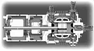
FIG. 9 -Reciprocating Compressor Cylinder Cross Section
Reciprocating compressor components include:
1. A piston with rings and rider bands, cross head, and piston rod, which moves back and forth with each rotation of the crankshaft. The rings act like seals to keep gas from bypassing the piston. Rider bands are wide ring shaped devices that support the piston in the cylinder and prevent the two from touching. Some reciprocating compressors are "single acting" and some are "double acting". Single acting reciprocating compressors compress gas only when the piston is moving in one direction. When the piston moves toward the cylinder head the gas is being compressed but when the piston is moving away from the head, suction is pulling gas into the cylinder.
2. Double acting compressor cylinders compress gas on both movements of the piston. When the piston is moving toward the head of the cylinder it is compressing gas as well as putting it into the process. At the same time the piston is on the suction stroke of the crankcase half of the cylinder. When the piston begins to move toward the crankshaft the crankshaft half of the cylinder is on compression and the head end is on suction. The effect is that there is almost twice the output from a double acting cylinder as from a single acting one.
A compressor cylinder contains the internal pressure and supports the reciprocating piston. The cylinder has a head on each end with water passages to remove some of the heat of compression.
The outer head may include something called a clearance pocket for adjusting compressor output.
The crank-end head has high pressure packing that fits around the piston rod. Its purpose is to keep the pumped gas from leaking past the rod and into the distance piece.
3. A set of suction and discharge valves. Reciprocating compressor valves are essentially check valves. The suction valves permit flow into the cylinder but not back out, and discharge valves permit flow to exit the cylinder but not return back in. Suction and discharge valve failures are the most common component failure in a reciprocating compressor. Unloaders may be part of the suction valve assembly.
i. There are three ways of controlling the output of a reciprocating compressor that is motor driven (constant speed): reducing suction pressure; adding a clearance pocket to the cylinder by opening and closing the valve that separates the cylinder from the additional volume in the clearance pocket; activating unloaders on the intake valves, which will hold them open.
4. A crank shaft, crank case, and connecting rods. Some reciprocating compressors have two lube systems, one for the crank shaft and cross head and another for the cylinder and packing. The lubricant may be the same in both lubricating systems, but in some cases is different. Be careful not to mix or switch the two oils if they are different.
If all the compression components are working properly, the flow through a compressor cylinder is controlled by 1) the compressor speed, 2) the displacement of the piston within the cylinder, and 3) the suction pressure. Increasing either the compressor speed, cylinder displacement, or suction pressure will increase the net flow through the cylinder and the horsepower required from the driver.
However, the design flow through a compressor cylinder can be reduced by numerous factors, such as internal leakage at the piston rings or valves, preheating of the inlet flow because of high ambient temperatures, a fouled exchanger on the suction gas, a lower suction pressure, etc.
Reciprocating compressors are often equipped with valve unloaders and clearance pockets as a means of controlling compressor throughput. If these flow control components malfunction, compressor flow may decrease dramatically or even drop to zero. Unloaders are control elements designed to hold intake cylinder valves open when they are activated, so that no gas can be trapped or compressed inside the cylinder during the compression cycle. Therefore, any compressor cylinders with activated unloaders will not able to contribute any flow to the compressor's total flow. The more unloaders that are activated the lower the total flow will be. Unloaders may be operated independently or in groups to produce the desired number of compressor "load steps." In contrast, clearance pockets are used to add or remove internal volume within a compressor cylinder, which in turn adjusts when the intake valves open and varies throughput. Generally, as flow is decreased with the use of unloaders and/or clearance pockets, the required horsepower decreases. Conversely, as flow is increased with the use of unloaders and/or clearance pockets, the required horsepower increases.
Troubleshooting Tips:
• If the differential pressure (i.e. the difference between the discharge pressure and the suction pressure) across any compression stage increases, the discharge temperature will increase on that stage. Conversely, if the differential pressure across any compression stage decreases, the discharge temperature will decrease on that stage.
• If the compressor speed increases, the net flow will increase. The horsepower required by a compressor increases at higher speeds, which should be reflected by increasing amps or kilowatts. Conversely, if the compressor speed decreases, the net flow will likely decrease. The horsepower required by a compressor at lower speed will decrease, which should be reflected by decreasing amps or kilowatts. This relationship between compressor speed and horsepower is not seen on motor driven compressors unless the motor is equipped with a variable speed electrical drive.
• If the molecular weight of the gas being compressed increases, the required horsepower will also increase. Conversely, if the molecular weight of the gas being compressed decreases, the required horsepower will decrease.
• If the suction pressure increases, the mass flow and required horsepower will also increase due to an increase in the gas density. Conversely, if the suction pressure decreases, the mass flow and required horsepower will decrease. If a higher suction pressure puts more gas into the compressor, more horsepower will be required to achieve the same pressure.
• If a multistage compressor begins to lift a relief valve between stages, the stage downstream of the relief device needs to be checked as it is not "keeping up" with the previous stage.
• If throughput falls quickly, check to insure all unloaders on intake valves are functioning correctly and not allowing the intake valves to close. If clearance pockets are used to control compressor throughput normally, insure the valve that controls their addition or removal from the cylinder volume are closed to separate them from the cylinder.
These relationships will help to troubleshoot reciprocating compressors that are not performing as expected. When reporting a problem with a compressor, always list the symptoms that caught your attention, such as a low flow, high amps, knocking sound, vibration, not enough pressure, etc.
Reciprocating Compressor Start-ups:
Most large reciprocating compressors have a jacking or barring gear to allow the compressor to be turned over to insure that there is no liquid in any of the cylinders prior to starting. The compressor should be barred over at least twice before attempting to start a compressor. Reciprocating compressors are normally started with an open spillback line to minimize the process load on the driver. This method allows the circulation of some gas, while rotating the compressor and driver under a light load. Keep in mind that every compressor is unique in its design and construction, and therefore should have its own customized procedure to ensure all necessary steps are followed during start-ups. Only approved procedures that follow the manufacturer's recommendations and experience with this compressor in this application should be used-attention to detail is paramount.
Once full load conditions (i.e. speed, temperature, pressure, and flow) are reached, use the "Reciprocating Compressor Checklist" below to monitor machine condition and performance.
Continue to monitor compressor conditions for at least an hour to make sure that everything is normal.
If problems are encountered during this start-up phase, either call in help for a second opinion or shutdown until additional technical assistance is available.
Reciprocating Compressor Checklist
• Net flow through the compressor. If the flow is low, check for open bypass valves and, if unloaders are used, if they functioning correctly. If the flow is too high, check the compressor speed and suction pressure.
• Suction and discharge pressure. Are the pressures normal? Remember, when troubleshooting, check the easy things such as valve positions, compressor speed, etc. first. Ideally there are pressure gauges on the suction and discharge pressure gauges and in-between stages.
• Suction and discharge temperatures. Are the temperatures normal? If not, begin to troubleshoot the system to find out what has changed. If the suction temperature is normal but the discharge temperature is high, you may be looking at an indication of internal wear or fouling valves. Use an infrared gun, contact pyrometer, or camera to check for hot valves.
• Oil pressures and levels. Check both crankcase oil and cylinder lube in case they are different.
Watch for increasing crankcase levels which normally means water is entering the lubricant.
• Bearing temperatures. Are the bearing temperatures higher than normal? If temperatures are found to be elevated, first check over the lubrication system to ensure flows are normal and that supply oil temperatures are normal.
• Vibration of piping, compressor casing, or skid vibration. Are vibration levels normal? If not, have someone from the vibration department analyze the situation to determine what may be wrong.
• Packing leakage. Check for high pressure and ensure that distance pieces are not filling with liquid. Make sure liquid traps are working properly.
• Drainage traps. If there are "knock outs" between stages with traps for draining them, notice how much liquid is draining. If it is possible that liquid is entering a reciprocating compressor cylinder it can wreck the compressor completely in a very short time.
Common causes of problems to watch out for:
• Abnormal rotational speed (This is generally not a problem if the compressor is motor driven because motors are constant speed devices.)
• Abnormal suction pressure. Low pressure can be caused by a partially opened suction valve or by blockages up-stream of the first stage. High suction pressure can be caused by a control valve problem that regulates the pressure to the compressors first stage.
• Abnormal discharge pressure. A high discharge pressure can be caused by a blockage down stream. A low discharge pressure can be caused by one of the preceding stages not compressing properly or low inlet pressure to the first stage.
• Abnormal gas density-especially if process upsets that can change the gas composition have been known to occur during previous start ups.
• Internal gas slippage due to leaking piston rings
• Plugged suction strainer that can result in a drop in flow or a loss of pressure.
• Discharge restriction due to downstream plugging or a partially closed valve.
• Broken valves will be evident by being much hotter than other valves. This condition can be caused by a bad valve with broken internals, a broken valve gasket, or a bad seat.
• Fouled compressor valves due to dirty gas will generally affect the output of the cylinder with the fouled valves.
• Unusual gas temperatures due to a loss of cooling somewhere in the process, usually caused by fouling or obstruction. Check intercoolers and after coolers on both the process side and water side.
Criticality
Compressors of all classes and designs should be monitored closely because they tend to be high energy, high-horsepower machines. In many cases, they are unspared, which makes them highly critical to the processes they support. When they fail management takes notice.
Because compressors tend to represent the most critical machines at most sites, it makes sense to watch them closely and keep them maintained and operating efficiently. Here are just a few ways to ensure your compressors perform safely and reliability day in and day out:
1. Perform daily inspections
2. Check compressor performance on a regular basis. Keep process logs in order to know what is normal. Look at the logs; historical process logs will help you know how your compressors were performing yesterday, last week, and last month.
3. Analyze the lubricating oil regularly by checking levels and color of oil. Increasing oil level, in the crankcase, can mean water building in the crankcase.
4. Watch rod drop indicators and other indicators of potential problems on a daily basis.
5. If a divider block is used for lubrication, check for any indicator pins that may be popping out, indicating blocked lubrication to a cylinder or packing.
6. If there is a panel for high pressure packing leakage, monitor it for increased flow. Check flow on sweeps of distance pieces.
7. Operators should help perform regular maintenance as prescribed by the manufacturer when appropriate or during turnarounds in order to learn more about a compressor's internal construction. This type of hands-on knowledge is invaluable when troubleshooting and can make you feel more comfortable when inspecting and operating these machines.
QUIZ
1. A is a fluid handling machine that takes gas at a lower density and pressure (in the suction nozzle) and compresses it by performing work on the gas so that it reaches a higher density and pressure (in the discharge nozzle).
2. Name two key reliability indicators for compressors.
3. What are the two main compressor design categories?
4. compressors work by accelerating gas with a rotating impeller or set of rotating blades and then converting the exiting high velocity gas stream into a higher pressure by decelerating the gas stream for the next compression stage.
5. compressors work by continually forcing gas into a smaller and smaller volume, either with a piston or with tight fitting rotors, and then expelling the reduced compressed volume into a discharge passageway.
6. List at least four (4) common causes of centrifugal compressor problems.
7. List at least four (4) common causes of reciprocating compressor problems.
Answers:
1. A compressor is a fluid handling machine that takes gas at a lower density and pressure (in the suction nozzle) and compresses it by performing work on the gas so that it reaches a higher density and pressure (in the discharge nozzle).
2. Temperature and vibration are two key indicators of compressor health.
3. What are the two main compressor design categories?
a. Dynamic compressors
b. Positive displacement compressors
4. Dynamic compressors work by accelerating gas with a rotating impeller or set of rotating blades and then converting the exiting high velocity gas stream into a higher pressure by decelerating the gas stream for the next compression stage.
5. Positive displacement compressors work by continually forcing gas into a smaller and smaller volume, either with a piston or with tight fitting rotors, and then expelling the reduced compressed volume into a discharge passageway.
6. List at least four (4) common causes of centrifugal compressor problems.
a. Low or high rotational speed
b. Low or high suction pressure
c. Low or high discharge pressure
d. Gas is too light or too heavy
e. Internal wear, due to loss of inter-stage seals
f. Internal fouling
g. Plugged suction strainer
h. Discharge system restriction due to a partially closed valve.
i. Power loading. High power levels may be due to a higher than normal speed, heavier than normal gas or higher than normal differential pressure.
7. List at least four (4) common causes of reciprocating compressor problems.
a. Low or high rotational speed
b. Low or high suction pressure. A low suction pressure can be caused by a partially opened suction valve.
c. Low or high discharge pressure. A high discharge pressure can be caused by a partially open discharge valve.
d. Gas is too light or too heavy
e. Internal wear due to leaking piston rings
f. Plugged suction strainer
g. Discharge system restriction due to downstream plugging or a partially closed valve.
h. Broken or fouled compressor valves