AMAZON multi-meters discounts AMAZON oscilloscope discounts
Drivers, Speed Modifiers, and Driven Machines:
Process machinery is typically composed of a group of sub-elements that convert one type of energy into another until it is finally transferred into a useable form of fluid power within a process. Here is a simple flow chart showing how power flows through a machine train.
Energy (in) --> Driver --> Speed Modifier --> Driven Machine --> Process Fluid Power (out)
Machine train sub-elements are normally interconnected using flexible components called couplings.
FIG. 1 illustrates a simple machine train comprised of an electric motor directly coupled to a centrifugal pump.
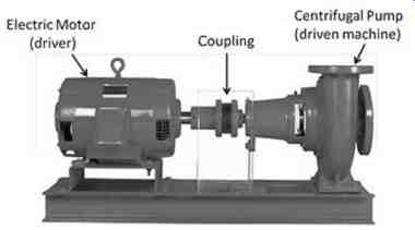
FIG. 1-An electric motor coupled to a centrifugal pump
Energy, such as electrical power, steam power, or fuel gas, is first converted into rotational output power. The speed of the driver output shaft may be increased or decreased by a speed modifier, i.e. gearbox or pulleys, depending on the requirement of process machine being driven. Finally, the output speed from the speed modifier powers the driven machine that produces fluid power in the process.
TBL. 1 contains common designs for driven machines, drivers, speed modifiers, and combination machines.
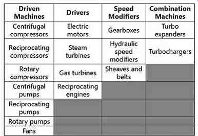
TBL. 1-Common types of process machinery elements
Driven Process Machines
The purpose of a driven process machine is to deliver a given process fluid, at a given flow and pressure, to specific points in a process. Driven machines receive the power input from a driver or speed modifier and convert it into fluid power at the process machine's discharge flange. All driven process machines are composed of an input shaft, a casing to contain the process fluid, a suction nozzle for input flow, a discharge nozzle for output flow, bearings to support the rotor (or rotors), and one or two end seals to prevent process leakage into the atmosphere.
There are many different designs employed to convert rotary power into fluid power.
Process machines that move and compress gases are called compressors or fans and process machines that move liquids are called pumps. There are too many designs employed in the process industry for us to cover them all adequately here. Instead of covering all design types, this SECTION will concentrate on centrifugal and positive displacement pumps. Compressors will be covered in SECTION 5.
Centrifugal pumps
Centrifugal pumps are one of the most common types used in industry. FIG. 2a shows a generic, single stage centrifugal pump and FIG. 2b illustrates a multistage centrifugal pump. These pumps can utilize either open or closed impellers and may have single or multiple stage designs. Centrifugal pumps utilize Bernoulli's principle to develop pressure (see Bernoulli's Principle Explained below) by first increasing the fluid velocity inside an impeller and then decreasing the fluid velocity in the discharge nozzle. These pumps consist of a shaft with bearings for support and an impeller as well as a pump casing. To prevent leakage from the pump casing to the atmosphere, most pumps employ packing, single or dual mechanical shaft seals.
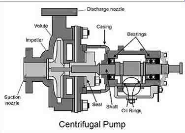
FIG. 2a-Single Stage Centrifugal Pump
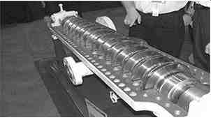
FIG. 2b-Multistage Centrifugal Pump
Centrifugal pump performance is typically presented graphically with a series of curves similar to the group shown in FIG. 3. The manufacturer usually provides curves that describe how flow, differential head, net positive head required, and efficiency change with pump flow.

FIG. 3-Centrifugal Pump Curves
Useful centrifugal pump facts:
• The suction or inlet nozzle to the pump is always bigger than the discharge nozzle.
• If a centrifugal pump has more than one impeller inside of it is called a multistage pump. If it has, for example five impellers in it, then it is a five stage pump.
Series and Parallel Operation
Centrifugal pumps may be operated in a series or parallel (see FIG. 4) configuration. When operating pumps in series, the pressure is increased across each pump, but the flow through each pump is identical (minus any minor flow losses due to leakage). When operating in parallel, the pressure rise on each pump is identical, but the total flow is increased. However, the overall flow is not doubled with two pumps operating in parallel because of "system head" or pressure. The easiest way to understand system head is to remember that the discharge pipe size stays the same diameter and therefore tends to restrict the higher flow generated by two pumps operating in parallel. This bottleneck effect means that two pumps operating in parallel will always deliver less than twice the flow that one pump can deliver.
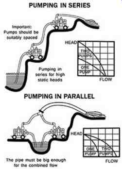
FIG. 4-Pumps in series and parallel
Bernoulli's Principle Explained
There are three physical forms of a fluid energy: Elevation energy, pressure energy, and velocity energy. The higher a liquid is stored, like water in a water tower, the greater its potential energy.
The greater a fluid stream's pressure, the greater it's potential to do work. Similarly, the greater the velocity of a stream of fluid, the higher its capability to do work. As a fluid flows down a pipe, ditch, or river, there is a constant interaction between these three forms of energy.
The interplay of the three forms of fluid energy in a flowing stream is governed by Bernoulli's principle. Originally formulated in 1738 by the Swiss mathematician and physicist Daniel Bernoulli, it states that the total energy in a steadily flowing fluid system is a constant along the flow path. An increase in the fluid's speed must therefore be matched by a decrease in its pressure, i.e., energy is always conserved in a fluid stream.
• This principle explains why a moving stream of liquid or gas exerts less pressure than if it were at rest. Bernoulli's Equation can be used to approximate flow parameters in water, air, or any fluid stream that has very low viscosity as long as the fluid is assumed to have these qualities: fluid flows smoothly fluid flows without any swirls (which are called "eddies") fluid flows everywhere through the pipe (which means there is no "flow separation") fluid has the same density everywhere (it is "incompressible" like water) In basic terms, the Bernoulli principle states that:
• At a constant velocity, if the elevation of a fluid stream increases, the pressure in the stream will decrease.
• At a constant velocity, if the elevation of a fluid stream decreases, the pressure in the stream will increase.
• At a constant elevation, if the velocity of a fluid stream increases, the pressure in the stream will decrease.
• At a constant elevation, if the velocity of a fluid stream decreases, the pressure in the stream will increase.
The last rule is the reason centrifugal pumps and centrifugal compressors are able to convert a high velocity flow from a rotating impeller into high pressure.
We can use the example of how an airplane wing works to better understand Bernoulli's principle.
Because of the wing's shape, air moving over the top of the wing must travel farther and therefore faster than the air traveling across the bottom of the wing. This difference in air velocities results in a lower pressure across the top of the wing than under the wing, resulting in a net upward force that can lift an airplane. An easy way to remember Bernoulli's principle is as follows: If the fluid's velocity increases the pressure decreases; and if the fluid's velocity decreases the pressure increases. These two relationships are inversely proportional. ( FIG. 5)
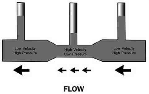
FIG. 5-Venturi (constricted pipe), demonstrating Bernoulli's principle.
As the fluid travels from right to left it starts at a low velocity and high
pressure in a wide portion of the venturi. As the velocity increases in the
narrow portion, the pressure drops. As the velocity decreases in a wider
portion the pressure again increases.
Troubleshooting Centrifugal Pumps
Here are some useful relationships to remember when dealing with centrifugal pumps:
• If the pressure on the discharge pressure gauge is increasing, the flow is likely decreasing.
• If the flow is increasing, the horsepower required by the pump is increasing, which should be reflected by increasing amps or kilowatts.
• If the fluid viscosity is increasing or getting thicker, the discharge pressure will fall and the horsepower required by the pump will increase.
• If the flow is increasing, the net positive suction head required (NPSHR) will need to increase to prevent cavitation (see definition below).
Cavitation is a serious operating condition that sounds like gravel is passing through a pump. This unique "gravelly" sound associated with cavitation is due to the fact that vapor cavities or bubbles are continually forming and then collapsing in the pump's inlet. If cavitation is not addressed and corrected quickly, the internal components of a centrifugal or positive displacement pump may be seriously damaged.
Cavitation is caused by either 1) operating a pump too close to the boiling point of the liquid at its suction or 2) by trying to pump more than a pump is designed to handle. Pump designers use a term called net positive suction head (NPSH) to determine whether there is enough suction pressure to prevent cavitation. Typical net positive suction head requirements can be seen in FIG. 3 (Centrifugal Pump Curves), where they are depicted as dotted vertical lines, labeled: 2', 2.5', 3', 3.5', 4', 4.5'. 2' means that at this particular flow, two feet of liquid suction head is required to prevent cavitation, 2.5' means that at this particular flow, two and a half feet of liquid suction head is required to prevent cavitation, and so forth.
As an operator, you simply need to remember that the higher the flow rate out of a pump the greater the suction pressure must be to insure that cavitation does not take place. An operator is in the position to control some parameters that will affect NPSHA. For example, if the pump is taking suction from a tower or tank, either the liquid level or the pressure can be increased as a means of stopping or reducing pump cavitation. Reducing the pump flow can have a positive effect on the NPSHA as well and may stop cavitation.
Responding to Pump Problems
When you detect a pump problem and decide to act, always list the symptom or symptoms that were noted on the work request, such as not enough pressure or flow, a seal is leaking, the drive motor is tripping off line, there is high vibration on the pump, etc. Do not list what should be done about the suspected problem on the work request. Comments such as: fix the pump, change the pump, replace the pump, etc. are not helpful to the maintenance planner. Comments such as: Seized, vibrating, low pressure, tripping off line, etc. are helpful. Always, allow the maintenance crew to investigate the situation and perform what they think are the necessary corrections, adjustments or repairs.
Problems that overhauling equipment will not solve:
• Plugged suction strainers.
• Plugged discharge strainers.
• Air leaking into a suction flange.
• Check valve on standby pump leaking.
• Pump turning backward.
• Wrong pump speed.
• Bypass valve open requiring too much flow.
• Blockage downstream of the pump.
• Too much flow being required from the pump.
• All of these should be checked before writing a work request for repair.
Positive displacement pumps
Positive displacement pumps (see Figures 6 and 7), unlike centrifugal pumps, theoretically can produce the same flow at a given speed (RPM) regardless of the discharge pressure. Thus, positive displacement pumps are constant flow machines. However, a slight increase in internal leakage as the pressure increases prevents a truly constant flow rate. As the pump is turned faster, more liquid is ejected from the pump. There are only two ways to increase output where a positive displacement pump is used-turn it faster or buy a bigger pump.
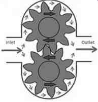
FIG. 6-Gear Pump

FIG. 7-Screw Pump
In this type of pump, flow on the discharge side of the pump must never be stopped because discharge pressure will continue to build until something is damaged. There are many types of positive displacement pumps, but regardless of how a particular unit is configured, the results are the same.
As the pump turns, the liquid inside it is trapped and must have a place to go. Positive displacement pumps have the same size inlet and outlet. On many of these pumps the suction and discharge can be changed by turning the pump in the opposite direction. Without a functional relief device on the discharge of the pump, catastrophic damage could occur.
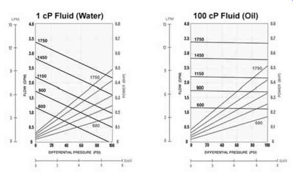
FIG. 8-Positive Displacement Pump Curves
Positive displacement pumps also have performance curves (see FIG. 8 above), but they tend to look quite different than centrifugal pump curves.
Useful relationships to remember when dealing with positive displacement pumps include:
• If the discharge pressure is rising, the required horsepower is also rising.
• If the pump is required to deliver more flow (e.g.-gallons per minute, barrels per day, etc.), then the speed of the pump must be increased or a larger pump is required.
• If the viscosity of the fluid is increasing, then the horsepower required to pump the fluid is also increasing.
• If the pump flow is increasing, then the net positive suction head required to prevent cavitation must also increase.
These basic relationships can help to troubleshoot a problematic positive displacement pump. When you detect a pump problem and decide to act, always list the symptom or symptoms that were noted on the work request, such as 'not enough pressure or flow', 'the outboard seal is not sealing', 'there is high vibration on the pump', etc. Allow maintenance to evaluate the situation and determine the proper course of action.
Drivers
A driver is any machine that takes electrical, steam, or fluid energy and converts it into rotary power that can be used to drive a process machine. The key attributes of a driver are reliability and efficiency. Various types of drivers are employed depending on the requirements of the driven machine and the available energy sources. For example, if electrical power is available and a constant speed is required for a driven machine, then an electrical motor can be used. If steam is available and variable speed is required to drive a process machine, then a steam turbine can be utilized. Steam turbines can be very efficient by driving a piece of equipment such as a pump and reducing steam pressure at the same time, eliminating the need for a steam let down or control valve.
If there is a difference between the design speed of the driver and its driven machine, a speed increaser or decreaser may be required to properly couple them. Gearboxes and a system of sheaves, belts, or chains can be used to transmit the required power and the required rotational speed. Size, cost, efficiency, and reliability are all factors an engineer considers when selecting the type of speed converter to be used.
Electric Motors
Electric motors are the most common type of rotating equipment driver in most process facilities.
They are used not only to drive pumps but also to drive many other types of equipment found in industry. FIG. 9a below shows a totally enclosed, fan-cooled (TEFC), electric motor, which consists of two major components (see Figure 19b)-A rotating element, called the rotor, and a stationary housing encircling the rotor, called the stator. A stator is composed of a set of stationary electrical windings that generate a rotating magnetic field created by the three phase electric power connected to them.
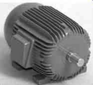
FIG. 9a-Electric Motor with TEFC Enclosure
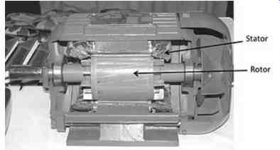
FIG. 9b-Electric Motor Cutaway
Three phase power, commonly used throughout industry, is composed of three circuit conductors carrying three alternating currents (of the same frequency but 120 degrees out of phase). From an operations point of view, three phase power means that if any two leads connecting the motor are moved to a new mounting location externally at the connection to the power source, the direction of the motor will be reversed. Remember that, because many types of equipment must turn in a specific direction to perform properly, it is imperative that the direction of rotation of a newly wired electric motor be checked before installing the coupling between the driver and the driven machines.
As a general rule, if you touch a motor and it is too hot to keep your hand on it, it is likely that the motor is running heavily loaded. The fins on the outside of a motor are to aid with cooling and to stiffen the stator. These should be kept clean and clear of debris and insulation. Quite simply, the hotter a motor runs, the shorter its life will be.
There are many factors in determining what is too hot, such as the class of insulation and the load on that motor at a given time. The best analysis is done by knowing what normal temperatures are and by responding if a significant change in the operating temperatures is noticed. Additional information, such as the significance of the change, may mean getting help from an acknowledged professional.
Normally, a motor will not fail immediately due to higher operating temperatures. The effects of high temperature operation are cumulative and manifest themselves over time, resulting in a shortened service life. Large motors with an enclosure for placement outdoors need to be checked to ensure the screens or filters that protect the windings in the stator stay clean. If they become clogged, the temperatures may go up and the motor life may be significantly reduced.
Steam Turbines Steam turbines, which can be likened to a child's pinwheel, are another common driver for industrial equipment (See FIG. 10a). The turbine may have multiple "pinwheels" or stages with the wind replaced by steam. The shafts are sealed to keep the steam from leaking out. The seals preserve the heat and the treated water and keep the steam from going where it is not wanted. Badly leaking steam seals can result in steam entering the bearing housings and where it condenses. The water will then return with the oil to the reservoir. Because the oil pumps draw near the bottom of the tank, eventually they will be circulating water, or a mixture of water and oil. We already know that a mixture of oil and water is a poor lubricant and therefore can lead to rapid bearing damage.
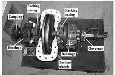
FIG. 10a-Steam Turbine
If steam is seen leaking out of the turbine, the reservoir should be checked to ensure that large quantities of water are not accumulating there. The easy way to do that is to look for increasing oil level. Some turbines have cooling water being supplied to the bearing area. Touch the inlet and outlet water lines to determine if heat exchange is taking place or at least that flow is present. Watch for oil leaks, as the oil may collect in the insulation and come in contact with the hot piping or casing, causing a fire.
Another inspection point on these small turbines is the overspeed trip mechanism. The level should be well seated or it could fall at any time causing the turbine to trip and potentially shut the plant down. See FIG. 10b.
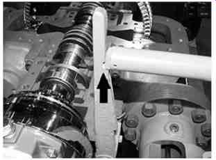
FIG. 10b-Steam turbine with overspeed trip mechanism and valve
Notice if the steam turbine seems to vibrate more when it rains than when the day is sunny. The insulation may allow water to enter and cool the casing in an uneven manner, affecting alignment and how smoothly the turbine runs. Only operators are likely to notice these subtle sets of cause and effect associated with steam turbines.
Gear boxes
Gearboxes (see FIG. 11) are often used whenever there is a large difference between the speed of the driver and the driven piece of equipment, high horsepower is required to be transmitted or input and output shafts need to be in different directions. A speed increaser is one where the input shaft is turning slower than the output shaft. A speed reducer is the opposite.
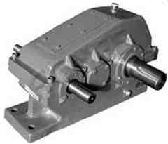
FIG. 11-Gearbox
From an operator's or casual observer's point of view, the most notable items when passing by a gearbox are the sound the gears are making and the feel of both temperature and vibration when touched. They need to be compared to the usual levels. Have they changed from what is accepted as normal and if so, "why". Always check foundation bolts by looking for oil being squeezed in and out between the base plate and the foot of the gear box. Look at the shims as well. Do they look like they have been squirming out? This is a potential sign of looseness or high vibration at some time.
Occasionally check the foundation bolt or nut to ensure it is tight. This bolt could be broken off in the foundation (not easily detected), relaxing its grip on the rotating equipment. If, when trying to turn the bolt, it moves, then it is likely the stud in the foundation that is broken.
Useful Gearbox Facts:
The input and output shaft direction of rotation will depend on how many gear shafts are inside the gearbox. An even number of gear shafts equals opposite direction of rotation for input and output shafts; an odd number of gear shafts mean the same direction of rotation for input and output shafts.
Equipment Components
The overall reliability of process machines depends in large part on the reliability of their components, such as bearings and seals. Each bearing and seal design comes with its own set of challenges. If the proper bearings and seals are selected and maintained, you can expect long service lives from your machines. The following is a brief explanation of the various types of bearings and seals commonly found in process machinery.
Bearing Types
Bearings play crucial roles in machine reliability and performance. Bearings maintain the position of rotors, so that internal clearances are maintained for efficient operation, while preventing the contact between the rotating and stationary parts. A bearing failure will lead directly to a machine failure.
There are many different types of bearing designs. Plain and rolling element bearings are two of the most common in process machinery.
Plain
Plain bearings, also referred to as journal bearings or bushings, represent a general category of bearings that are the simplest in terms of design. They consist of a bearing material that is usually stationary and a rotating shaft (see FIG. 12). They may be lubricated by any of the methods of lubrication mentioned in the lubrication section ( SECTION 2) of this guide.
One type of plain bearing is called the pillow block bearing. Many of the larger ones have water connections going into them for cooling. Normally a water cooled pillow block bearing will have a water-in and out line on the same side of the bearing and a loop or "U" on the other side. Many times these lines are rubber hoses that can dry out and crack after years of exposure to the outside elements, allowing the cooling water to bypass the bearing and the oil to get too hot. Additionally, if poorly sealed where these connections enter the pillow block bearing, outside elements may enter the bearing oil. If a cooling water hose is leaking, it can contaminate the bearings lubricant by allowing cooling water to enter the bearing housing resulting in a bearing failure.
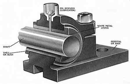
FIG. 12-Cutaway of a plain (journal) bearing and shaft
Rolling element
Rolling element bearings fall into a large category of rotor support bearings that include ball, roller, and tapered roller designs (see Figures 1.13). They can be lubricated by either grease or oil, depending on the manufacturer's recommendations. If a rolling element bearing is known to be running very hot, do not put a water hose on the outside of the housing. The water could get into the lubricant, causing a premature failure. The cooling water on the outer housing will shrink the outer housing and may cause the bearing to seize immediately, or at least have unintended consequences.
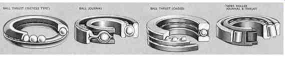
FIG. 13-Different types of rolling element bearings.
FIG. 14 contains a list of bearing types, categorizing them in terms of their construction. Plain bearings fall into two categories: metallic and non-metallic, with each of these types having many different design options. Similarly, rolling element bearings fall into two main categories: unmounted and mounted. Unmounted rolling element bearings can further be broken down as either ball or roller types. Mounted rolling element bearings can be broken down into design options, such as pillow block bearings, flanged units, cartridge units, and take-up units.
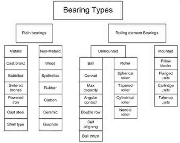
FIG. 14-Types of bearings
The main takeaway from FIG. 14 is that there are many types of bearing configurations available to machinery designers that utilize different materials and geometries. As an exercise, the reader can select a piece of equipment in a plant and determine the types of bearings it contains by talking to the people that maintain the equipment or by using the maintenance manual. It is beneficial for operators to understand what style of bearings a given machine uses in order to know how they must be maintained, and to be able to relate it to the information in the lubrication section in SECTION 2.
Pump Packing Rings and Mechanical Seals
Sealing a pump casing around the shaft periphery to prevent the pumped liquid from leaking into the atmosphere is a major concern. Through the years many seal designs have been invented and improved upon in order to ensure that product leakage rates do not exceed acceptable levels. Stricter and stricter leakage limits of regulated liquids have led to increasingly sophisticated seal designs. A wide range of designs satisfies most sealing requirements.
Effective pump sealing can be accomplished by using either packing or a mechanical seal. Years ago, most pump shafts were sealed using rings of soft packing compressed and held in place with a packing gland (see FIG. 15). This type of shaft seal required a fair amount of leakage just to lubricate the packing and keep it cool. Later, the mechanical seal (see FIG. 16) was developed to control leakage by utilizing two very flat sealing surfaces (one stationary and one rotating) inside the sealing cavity. The entire arrangement was designed to fit in the same volume of the original packing gland. Even though these mechanical seal faces also require some (very small) leakage across the faces, to cool and lubricate the seal faces, this leakage normally evaporates and is not noticeable.
Most pump shafts today are sealed by means of mechanical seals. However, because of the delicate components used for this new sealing method and the requirements of the seal support system, mechanical seal failures are the greatest cause of pump down time.
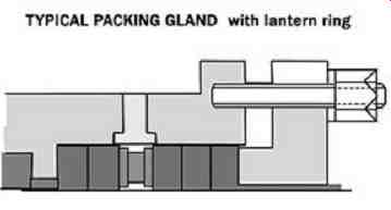
FIG. 15-Packing Gland
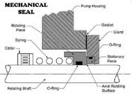
FIG. 16-Mechanical Seal
With today's technology, mechanical seal designs can suit most application requirements, including temperatures up to 500 degrees F and shaft speeds of 3600 RPM or more, for pumps, through the selection of the proper combination of materials and auxiliary seal support systems. Seals can be ordered in balanced configurations to seal pressures above 200 psi, and designed with multiple sets of sealing faces to handle extremely high pressure applications.
The part of the pump casing that contains the mechanical seal or packing rings is called the stuffing box (or with a mechanical seal, the seal chamber). Horizontal end-suction pumps and vertical pumps have only one stuffing box, whereas horizontal between-bearing pumps, such as those used on cooling towers for high flow and low discharge pressure, are provided with two stuffing boxes one on each side of the pump casing.
Packing versus Mechanical Seals
Gland packing and mechanical seals have both been successfully used for sealing pump shafts.
Countless engineering applications rely on these devices. Although mechanical seals and packing have similar functions, which one is used depends on budget, personal preferences, and more importantly, application requirements. A centrifugal pump moving either a flammable or hazardous fluid demands that a mechanical seal or seals be used to eliminate leakage to the atmosphere. On the other hand, there are applications where a packing is the more appropriate choice, such as cooling water service or other safe liquids such that that leakage will not result in safety or environmental violations. Some pros and cons of the different sealing methods are listed below.
Advantages of packing rings
1. Lower initial cost.
2. Very simple selection, installation, maintenance, and trouble-shooting.
3. The packing rings can act as an additional bearing to support the pump shaft reducing shaft deflection during extreme operations of the pump.
Disadvantages of packing rings
1. Require small amount of leakage for lubrication and cooling-therefore packing rings are unsuitable for use in liquids that are toxic, flammable, or otherwise hazardous or polluting.
2. Usually requires a stack of several packing rings for effective sealing. The act of sealing destroys the shaft or sleeve of the pump, making more expensive repairs.
3. Easily wears out, resulting in more frequent replacement of packing rings and increasing the leakage from the pump.
4. Requires substantially more power to be applied to the pump in order to overcome packing friction on the shaft or sleeve.
5. Because leakage can increase over time, if not adjusted often the leakage can enter the bearing housing and contaminate the oil with failure of the bearing resulting.
Advantages of using mechanical seals
1. Reduced energy usage on the pump due to lower frictional drag than traditional packing.
2. Will not wear out a shaft or sleeve in the same manner as packing rings.
3. Near zero leakage possible with a mechanical seal; packing requires some leakage (usually visible) for proper lubrication.
4. Require less periodic maintenance than packing if properly applied and its support system maintained.
5. Specially designed mechanical seals can be applied to higher pressures and speeds than traditional packing.
Disadvantages of using mechanical seals
1. Less tolerant to shaft deflection and misalignment.
2. Less tolerant to dirty or contaminated liquid.
3. May require expensive seal support systems which need to be maintained.
4. More expensive than packing rings.
Packing Inspections and Adjustments
It is important to inspect pumps with packing frequently to ensure that there is leakage and that it is not excessive. For most braided pump packing, liquid leakage is absolutely necessary to provide lubrication and cooling of the sealing surface and ensure the packing's long life. When adjusting pump packing, the goal is to arrive at the lowest acceptable leak rate while maintaining the life of the seal.
Optimizing packing leakage rate requires the operator to have experience with the combination of packing material and liquid being pumped. Over-tightening can cause the packing to fail very quickly and is the most common cause of packing failure.
When making packing adjustments the guiding principle is to make adjustments that are proportional to the leakage rate. If the pump is spraying large amounts of leakage, then larger adjustments can be made until the leakage is controlled in the form of one to several drops per minute. After leakage is reduced, further adjustments should be small. One-sixth of a turn on the gland nuts (one flat) can have a significant effect. Several minutes should pass before the next adjustment is made. Adjust all gland packing nuts equally when adjustments are made. Follow the packing manufacturer's recommendation on adjustments. If the packing gland follower, the outside part with the adjusting nuts, moves very close to the packing gland notify maintenance as the packing is very close to requiring a change out.
Some packings smoke on initial startup. Always check the manufacture's recommendations and information, so panic does not result.
Packing Leakage Paths
There are two principal paths that leakage can take out of the stuffing box (see FIG. 17):
• Inside diameter (ID) leakage occurs along the interface between the packing and the rotating shaft or sleeve. This leakage cools and lubricates the dynamic surface and is necessary for most braided pump packing applications. Leakage can also be between the shaft sleeve and the shaft. It may look like the packing to shaft or packing to sleeve leakage but it cannot be stopped by adjusting the packing.
• Outside diameter (OD) leakage exists when the liquid runs along the interface between the packing and the stuffing box bore. While it will have some cooling effect on the packing, this leakage is unnecessary because it will not serve as a lubricant for the spinning shaft and the stationary packing.
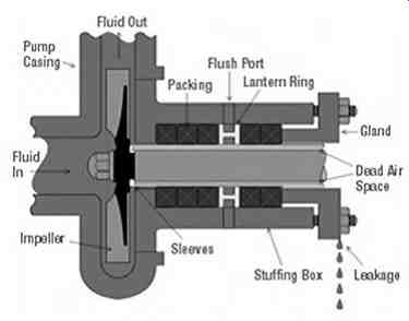
FIG. 17-Pump packing leakage paths
Mechanical Seal Inspections
Most mechanical seals never reach the end of expected life and wear out. If a suitable seal design is properly installed into a cool, clean, and low-vibration environment, it could last for 10 or more years before wearing out. In reality, we rarely see a failure due to reaching the end of a seal's useful life. Unfortunately, we all have to live with imperfect seal designs and installations that often meet a premature end. For this reason, it is important that pumps with mechanical seals be inspected frequently so that small seal leaks are detected before the leak worsens. A seal is considered to have failed when leakage exceeds environmental or plant-site operating limits. This is the area, on mechanical seals, where the operator can have the maximum affect. It is important to run the equipment correctly-never dry or with cavitation. The seal support system must be inspected and kept operating. There are liquid levels and pressures to be maintained and cooling water to barrier fluids or seal life will be significantly reduced.
Understanding the mode of seal failure can lead to better troubleshooting and identification of the root cause of the seal failure. There are numerous possible reasons for a mechanical seal to fail prematurely. Several of these are listed below, with the factors under an operator's control tagged with an "Operational Factor" notation:
1. Incorrect seal design or material selection for the application temperature, pressure, speeds, and fluid properties.
2. Seal component abuse before installation-including chipping, scratching, nicking, or allowing to become dirty.
3. Erroneous installation-including assembly, seal setting, or placing of components in the chamber.
4. Improper start-up, dry-running, or failure of seal support systems. Operational Factor: Make sure you are using the proper start-up procedure to ensure the seal chamber is fully vented and filled.
5. Seal support system. Operational Factor: Make sure the proper seal flush rate is applied, and the proper level is achieved and maintained in the barrier fluid system. Ensure cooling water is being supplied to the cooling coils in the barrier fluid system and that heat is being exchanged between the inlet and outlet of the cooling water lines on the barrier system and the inlet and outlet from the mechanical seal. The upper line should be warmer than the lower line from the seal.
6. Improper pump operation. Operational Factor: Make sure the pump is operating at a safe flow rate and is getting plenty of suction flow. Cavitation not only affects flow from the pump but can damage impellers and internal pump parts. It can be detected by a characteristic noise such as gravel or popping inside of the pump and the discharge pressure gauge needle is much more unsteady than normal.
7. Contamination of the sealing fluid with abrasive or corrosive materials. Operational Factor:
Watch for upset conditions that can lead to a contamination of the seal flush.
8. Equipment has excessive shaft run-out, deflection, vibration, or worn bearings.
9. Worn out seal-the seal achieved its normal life expectancy. After a seal failure, always check to see how long the seal ran before it failed to see if the failure was premature or not.
Every mechanical seal leaks. Mechanical seals may be used as single or multiple seals, sometimes called double seals. With single seals it is the product that leaks to the atmosphere. With double seals the user gets to choose whether the product or a barrier fluid leaks to the atmosphere. Double seals are normally used in dirty or hazardous services, and they use a barrier fluid between the two mechanical seals to prevent hazardous materials from escaping. The fluid between the seals may be at a pressure higher or lower than the stuffing box pressure, depending on the application. Gas seals are a relatively new type of seal where a gas (usually nitrogen) is introduced between the two mechanical seals and seal faces as the barrier fluid. These seals are becoming very popular because, when properly applied, there is little to no contact between rotating and stationary parts and thus no wear.
Nitrogen entering the pumped fluid normally does not offer a contamination problem.
A single mechanical seal may leak along one of five paths (see FIG. 18).
1. Seal face leakage is visible where the shaft exits the gland but not under the sleeve or at the drain connections.
2. Dynamic secondary seal leakage is visible where the shaft exits the gland or at the drain connections.
3. Static secondary seal leakage is visible where the shaft exits the gland or at the drain connections.
4. Gland gasket leakage is visible at the gland-seal chamber interface.
5. Hook sleeve gasket leakage or cartridge sleeve secondary seal leakage is visible where the sleeve ends outside the seal chamber.
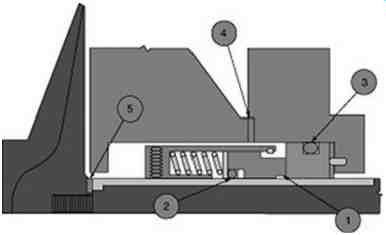
FIG. 18-Possible seal leakage paths
The first four of these locations result in visible seal leakage. Leaks at locations 1, 2, and 3 will show up at the ID of the seal gland. A leak at location 4 will show up at the OD of the seal gland.
Mechanical Seal Flush Plans
To attain long lives from mechanical seals, think of them as bearings whose faces must 1) be lubricated, 2) kept cool, and 3) kept free of debris. In challenging sealing applications, external piping systems called seal flush plans may be required to ensure a healthy environment is maintained at the mechanical seal faces. Maintaining seal flush plans is one key area that operators can have the most effect. Below are two of the many possible seal flush plans. These plans are referred to by an American Petroleum Institute (API) number.
API 21 flush plan ( FIG. 19) takes flow from the discharge of the pump, cools it using a heat exchanger, and then returns it near the seal faces. There are two common problems encountered with this seal flush plan: 1) plugging in the exchanger, and 2) fouling on the water side of the cooler.
During inspection rounds, always check to see that there is a temperature difference between the inlet and outlet lines. If the water outlet line is warm or hot, you can be sure cooling is taking place. These coolers should be back flushed at each shut down. If the seal flush cooler cannot be back flushed, let someone know so they can either be replaced or specially cleaned at the next opportunity. These are used in hot clean services such as hot condensate service.
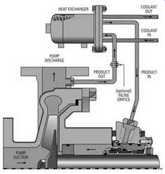
FIG. 19-API 21 flush plan-Product flow from pump discharge goes through
cooler before entering seal chamber
The API 32 seal flush plan ( FIG. 20) involves using a clean external flush to keep the mechanical seal faces cool and free of debris. A flush flow meter is recommended for this seal flush plan to provide a means of monitoring the flush rate. Place a mark or label on the flush rotor-meter so that you can tell what the correct flush flow should be. This arrangement may be used in hot or dirty service. The flush material being injected must be compatible with the pumped fluid and at a higher pressure than the stuffing box.
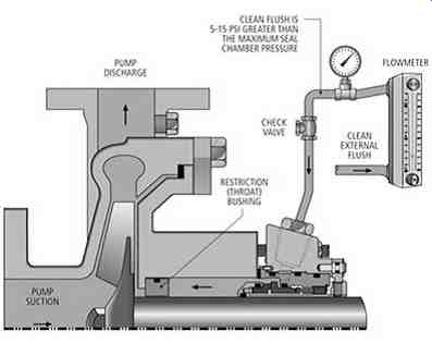 FIG. 20-API flush plan 32. An in-line flow meter is recommended to provide
a means of monitoring flushing flow
FIG. 20-API flush plan 32. An in-line flow meter is recommended to provide
a means of monitoring flushing flow
Heat exchangers
Process machinery tends to generate heat for several reasons: all bearings generate heat due to frictional losses, compressors generate heat through compression, and gearboxes create heat due to their inefficiencies. In order to maintain safe operating temperatures a way to remove heat created by process machines is often required. A heat exchanger is a device built for efficient heat transfer from one medium to another. It does not matter if the media are separated by a solid wall so that they never mix, or if they are in direct contact with the heat exchange surfaces. One of the most common types of heat exchangers in the chemical and petrochemical industry is the shell and tube (see FIG. 21).
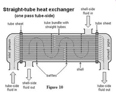
FIG. 21-Shell and tube heat exchanger
Heat exchangers can transfer heat in three different ways. They can use conduction, convection or radiation. For example, a motorcycle cylinder is a heat exchanger that uses all three methods.
Conduction is used from the cylinder and piston to the outside finned wall of the cylinder. When the motorcycle is moving and air is flowing over the fins convection is taking place. When stopped heat felt on the legs is from radiation. A common problem encountered in heat exchange equipment is fouling. Fouling can be caused when minerals in the cooling water precipitate out at high temperatures and plate out on metal surfaces. Eventually as scale builds up in a cooling water tube, it can reduce and even block off cooling water flow and dramatically reduce the exchanger's ability to remove heat. FIG. 22 shows a severely fouled exchanger tube. In some cases biological life can attach to the inside of tubes and restrict or prevent flow in the tubes.
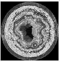
FIG. 22-Severely fouled heat exchanger tube
Quiz
1. List two types of bearings.
2. List two types of drivers.
3. List two types of driven machines.
4. When operating centrifugal pumps in series, the pressure is increased across each pump, but the flow through each pump is _______.
5. ________is a serious operating condition that sounds like gravel is passing through a pump.
6. On a centrifugal pump, what is likely happening to the flow if the pressure on discharge pressure gauge is increasing?
7. On a positive displacement pump, what is likely happening to the required horsepower if the viscosity of the fluid is increasing?
8. What are the two general categories of pump seals?
Answers
1. List two types of bearings.
• Plain
• Rolling element
2. List two types of drivers.
• Electric motors
• Steam turbines
3. List two types of driven machines.
• Centrifugal pumps
• Positive displacement pumps
• Centrifugal compressors
• Positive displacement compressors
4. When operating centrifugal pumps in series, the pressure is increased across each pump, but the flow through each pump is identical.
5. Cavitation is a serious operating condition that sounds like gravel is passing through a pump.
6. On a centrifugal pump, what is likely happening to the flow if the pressure on discharge pressure gauge is increasing?
• The flow is likely dropping.
7. On a positive displacement pump, what is likely happening to the required horsepower if the viscosity of the fluid is increasing?
• The required horsepower is likely rising.
8. What are the two general categories of pump shaft seals?
• Packing
• Mechanical Seals