AMAZON multi-meters discounts AMAZON oscilloscope discounts
(cont. from part 1)
3. Disposal structures
3.1 Disposal requirements
In Germany, radioactive waste is divided into two kinds:
- radioactive waste producing substantial heat [hot waste]
- radioactive waste producing negligible heat [cool waste]
The latter - minimal thermal radiation waste - can be compared with low radioactive waste, and to some extent with moderately radioactive waste. Radioactive waste producing substantial heat comprises highly radioactive and to some extent moderately radioactive waste.
Waste comes from decommissioning and operating nuclear power plants, from the nuclear industry, nuclear research, and, in very small quantities, from medicine and from the Bundeswehr (German armed forces), and includes contaminated tools, protective clothing, sludges and/or suspensions.
Radioactive waste producing negligible heat accounts for more than 90% of the total volume of waste, but just 0.1% of the total radioactivity of waste to be put into final storage in Germany.
3.2 Interim storage
Under the agreement between the Federal Government of the Federal Republic of Germany and the utility companies of June 2000 and the subsequent amendments to the Atomic Energy Act in April 2002, so-called on-site (decentralized) interim storage facilities were built at nuclear power plant sites between 2004 and 2007.
Decentralized interim storage facilities are those in which burned-out fuel elements are kept under controlled conditions at nuclear power plant sites for relatively long periods before being moved to final storage.
Interim storage facilities can be divided into two basic types:
- WTI design: Lightweight double-bay hall structures, walls approx. 70 cm thick, roof slabs approx. 55 cm thick, double-bay buildings consisting of two halls separated by a partition wall.
This model is based on the interim storage facilities at Gorleben, Ahaus and Lubmin/ Greifswald (northern interim storage facility).
Integrated operating areas with two cranes, stored in double rows (Figures 8 and 9)
- STEAG design
Solid single-aisle hall design with walls approx. 1.20m thick, roof slabs approx. 1.30m thick with separate operating building, one crane, compact storage (Figures 10 and 11).
The STEAG design was developed in view of using more cost-effective containment models in the future.
In accordance with the multiple barrier principle in nuclear technology the strengthened building structure and future containment generation are designed to serve as additional barriers.
Both models share the same basic features: single-storey reinforced concrete halls with wall and roof slab openings for natural cooling. Inside the halls, a partition wall separates the reception/trans-shipment area from the storage area. Both storage designs have 140t crane systems; the WTI halls need two of these because of their two-bay structure. For the building design of interim storage facilities see Section 3.2.3.
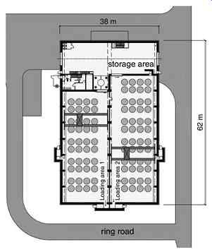
Fig. 8 Ground plan, WTI design
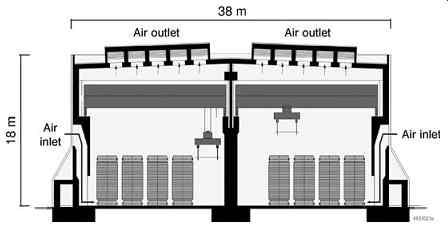
Fig. 9 Cross-section, WTI design
Once taken into store, the containers, which essentially contain irradiated fuel rods, can be described approximately as follows: height 6.50m, diameter 2.80m and a dead weight of 125t. The container walls in the cylindrical and floor areas are approx. 420mm thick.
The containers are sealed tightly using a cover system, using mainly CASTOR V/19 (Castor: cask of storage and transport of radioactive material) containers to date. These containers can hold up to 19 fuel elements (Figure 12).
The top of the container body is stepped to take the cover. At the head and foot of the container body are two overlapping carrying frames to which the storage hall crane lifting gear can be attached.
Containers are transported by rail or road exclusively and delivered to the interim store.
Storage containers are transported horizontally to be stored in the interim store.
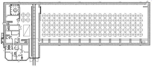
Fig. 10 Ground plan, STEAG design
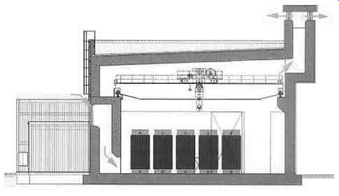
Fig. 11 Cross-section, STEAG design
To unload containers, the storage hall crane attaches to them via the carrying frames provided, and the transporter vehicle takes them. Containers are then driven to their preset storage positions, set down upright and connected to a container monitoring system.
3.2.1 Safety requirements
Safety requirements for structural systems can be deduced overall from the statutory requirement to prevent damage and from the safety goals to be complied with.
Specific requirements here are laid down in the nuclear rules, accident rules and KTA safety standards.
The storage building is required mainly to:
- provide shielding
- remove heat
- be designed for operating and exceptional loads
- provide protection against fire and lightning strike
- protect against the weather
- protect against third parties (sabotage).
3.2.2 Design criteria
Design criteria are governed by:
- Shielding
Most of the ionizing radiation that fuel elements emit is shielded by their containers. The reinforced concrete building structure provides further shielding, keeping radiation levels within the limits laid down by the radiation protection regulations and protecting staff and the environment.
- Heat removal
The interim storage facility design is designed to remove the heat that the fuel elements give off as they decay, by way of natural convection. The air inlets and outlets required must be arranged and dimensioned to remove heat reliably.
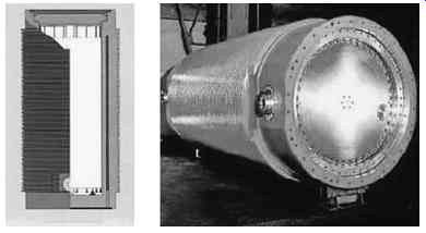
Fig. 12 CASTOR V/19 transport container
- Building settlement: Building settlement due to the container loads involved must not compromise the structure or the operation of the cranes etc. Settlement is estimated technically at the planning phase, allowing for subsequent partial occupation levels, and is monitored in operation via recurrent settlement testing.
- Structural integrity: As with conventional structures, this requirement can be met via the rules of building design on the design of the roof and sealing the building externally, if groundwater conditions allow.
- Floor structure and decontaminatable coatings: The slab and ground in the storage area must have sufficient compression strength and wear resistance to take the containers put into storage. This is achieved by using a mechanically smoothed concrete surface with hardening agents mixed in. In the reception and maintenance area, the floor is given a decontaminatable coating as a precaution. In the loading and unloading zone in the reception area a shock-absorbent layer of so-called damper concrete can be included in the floor slab to protect containers and floor slab if a container is dropped from a height of 3m, which cannot be ruled out.
- Durability
Interim storage facilities are designed to be permanent in accordance with conventional standards. If they are built properly of tried and tested reinforced concrete designs, they should last for their full working lives.
3.2.3 Building design
As we saw in Section 4.3.2, building structures in Germany fall into one of two different designs: WTI and STEAG. These designs differ from one another in particular in terms of their structural design.
WTI Design:
The building is designed to withstand exceptional effects from outside, such as earthquakes and blast waves from explosions. They do not need to be designed to absorb aircraft impact, as the containers themselves are designed for this external event.
Exceptional events from inside are containers falling from a height of 0.25m in the hall area and 3.00m in the loading area. In the trans-shipment hall, so-called damper concrete is used in areas in which containers could fall, to absorb the energy released, enabling the loads involved to be transmitted without additional strengthening the floor slab at this point.
When floor slabs are occupied by CASTOR containers in blocks of eight, this gives a floor slab loading of 200 kN/m^2.
What is not typical, compared with similar lightweight hall constructions, however, is the roof construction; this has to be 55 cm of normal concrete to be radiation-proof.
This high permanent load component means that this design has to have relatively high roof girder constructions.
STEAG Design:
The greater roof slab and wall thicknesses of the solid STEAG design will at least protect against penetration from aircraft impact. Unlike the WTI design, such halls can also hold containers designed for a debris load of 2t at least, should roof sections fall in.
Temperature effects The relatively high room temperatures of approx. 80 degr. C mean that the outer walls and roofs must be reinforced accordingly, to guard against a correspondingly high crack width, which must be demonstrated in many areas for centric forces as finally built (with the concrete at its full tensile strength).
The floor slabs are designed not merely for a high load per surface area of up to 200 kN/m^2, but also for hot spot temperature effects of approx. 120 degr. C immediately below the containers. This makes an additional consideration of the upper reinforcement of the floor slabs necessary. The hot areas cause concentric inherent stresses leading to cracking.
However, non-linear studies of floor slabs made at interim storage facilities have shown that no additional reinforcement is required because of the hot spot effect.
3.3 Final storage
The Federal Government of Germany has decided to store radioactive waste in final storage facilities in 'deep geological formations' to keep them out of the biological cycle for as long as possible. This decision was taken because of Germany's population density, climatic conditions and the fact that Germany has geological formations that are suitable for this purpose.
Both hot and relatively cool waste will be stored finally in deep geological formations for safety reasons.
Hot radioactive waste (from spent fuel elements) is more active, so the temperatures that radioactive waste generates are correspondingly higher. The Germans are still looking for the most suitable deep geological formations in which to store them finally.
Studies to date have shown that, highly radioactive hot waste can be safely stored finally in deep geological formations even with today's state of the art science and technology.
Germany has approved the Konrad shaft as the final storage facility for radioactive waste producing negligible heat.
The salt stock Gorleben site is currently the most studied site for a possible final storage facility for radioactive waste producing substantial heat.
Any further investigations have been interrupted by a politically motivated moratorium since 1 January 2000, and have not resumed to date.
The radioactive waste producing substantial heat obtained at present, such as spent fuel rods, is put into storage at the nuclear power plant sites themselves in interim site storage facilities in CASTOR containers.
Other radioactive waste producing substantial heat is prepared and put into storage in glass moulds at the final storage facility in Gorleben, which is also where the waste returned from the reprocessing plants in France and Great Britain is stored.
For radioactive waste whose thermal radiation is negligible, overground interim storage facilities have been set up as collection and buffer stores and as storage facilities, as no final storage facilities are available.
From 1967 to 1978, radioactive waste producing negligible heat - then called low and moderately active waste - was stored at Salzbergwerk Asse II (experimental final storage facility) under the strategy at that time.
Before it was used as a final storage facility, Asse II worked as a saltmine for more than fifty years; the waste is stored in the chambers excavated in the course of extracting the salt. The prevailing geological conditions led to the salt formations moving and loosening, so water penetrated into the mine, which means that Asse does not fully meet the integrity and stability requirements for a final storage facility. The German Federal Office for Radiation Protection, which operated the Asse final storage facility at that time, believes that the site safety conditions at the time only exist to a limited extent today.
As far back as 2007, the Federal Ministry for the Environment, Nature Conservation and Nuclear Safety instructed the Federal Office for Radiation Protection to refit the former Konrad shaft facility at Salzgitter as a final storage facility for radioactive waste producing negligible heat. The Konrad final storage facility has natural barriers which contain the radioactive waste permanently. Above the final storage facility, there is a covering layer of clay up to 400m thick which prevents surface water penetrating.
The storage areas are between the 800m and 850m strata.
Nine storage areas have been approved to allow for the storage space originally applied for of 605,000m3 . As matters currently stand, two storage areas capable of holding 280,000m3 of waste should suffice, as new conservation procedures have reduced the volume of waste involved.
Under the planning approval of 2002, the Konrad final storage facility can hold up to 303,000m3 of radioactive waste producing negligible heat. By way of comparison: a single CASTOR container with thermally radiant waste contains more radioactivity than the entire 303,000m3 of radioactive waste Konrad is allowed to hold.
By the time all the nuclear power plants in Germany have reached the end of their working lives, it is estimated that a total of approx. 17,000t of heavy metals will have accumulated as spent fuel elements, that is thermally radioactive waste producing substantial heat.
Final storage facilities for highly radioactive waste could be any geologically stable ground formations such as salt stocks or rock formations. The structural engineering challenges which final storage facilities present are in particular how to build the tunnels required to access the actual storage facilities and designing the storage facilities at great depths.
This model is the most advanced in the world, and was developed at the nuclear power plant site at Olkiluoto, Finland, where the deepest point achieved in the rock formations is approx. 420m. The highly active waste stored at this depth is fused into glass, and will be enclosed completely in concrete once it has cooled down to some extent.
4. Building execution
This section deals with aspects of building design execution which are specific to nuclear power plants, first looking back at the building of more recent nuclear power plants in Germany, which were built in the 1980s. We will also look at experience and current developments in constructing the Olkiluoto 3 (OL3) power plant in Finland.
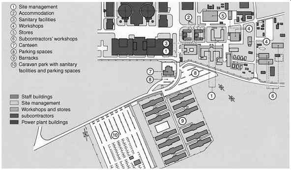
Fig. 13 Section of site installations plan KRB II Gundremmingen
4.1 Site installations
Construction sites for nuclear power plants are some of the largest construction sites there are, employing several thousand people.
A section from the site installation plan for KRB II Gundremmingen can be seen in Figure 13. Apart from the site management and workshop buildings, the infra structure is particularly important: barracks, a canteen to cater for the workers, utility and disposal lines and parking places must be designed and installed.
With the OL3 project, building the nuclear islands took 13 tower cranes at times, a stationary Demag PC 9600 crane with a capacity of 1000 t to install the steel components of the safety containment, plus mobile cranes to lift in the equipment to be used. Three of the tower cranes, two of them inside the reactor building, could not be supplied directly, but had to be served by other cranes (Figure 14).
An anti-crane collision system was used at OL3 which analyzed where crabs, out riggers and counterweights were and, if need be, restricted adjacent crane movements to prevent them colliding.
The crane layout selected allows all cranes to rotate freely with the crabs run in, at times when they were not in use, such as on rest days or in strong winds.
4.2 Project organization
Organizing who is responsible for what and how things should run is of decisive importance when creating a major project. Clients, authorities, inspectors, contractors and designers must be involved in the project in such a way as to ensure that work proceeds perfectly and in an orderly fashion and that quality goals are achieved. Any project organization is based on contractual foundations, which lay down the rights and obligations of those involved.
The overall project organization chart of the general contractor in charge of building the OL3 power plant as a whole, the consortium of AREVA NP and Siemens PG, is shown in Figure 15.
By way of example, some of the governing tasks in these areas are listed below:
Quality and environment
- Checking subcontractors' quality documents
- Auditing subcontractors' staff and own staff
- Monitoring the work of the other departments, to check that they comply with the quality assurance plan
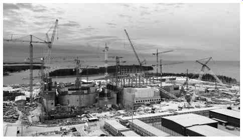
Fig. 14 OL3, cranes used on nuclear island - reactor building and auxiliary
buildings (left) and conventional island (right)
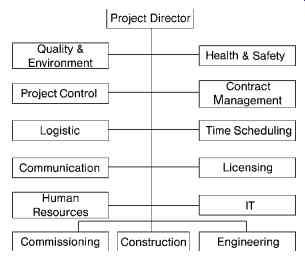
Fig. 15 OL3, general contractor's overall organization chart (as at 08/2009)
- Managing and leading the quality assurance teams for the individual trades
- Training site staff in quality assurance
- Assisting the construction and engineering teams in coordinating specifically with the client and the authorities
Project control
- Bookkeeping
- Contract management for subcontractors' contracts.
- Assisting subcontractors commercially
- Monitoring the subcontractors budget
- Invoicing (to client) Logistics
- Organizing delivery of plant components to site Communications
- Marketing/public relations
- Organizing site inspections
- Producing presentation documents
- Producing and approving site photos Human resources
- Dealing with staff employed on site Commissioning
- Managing and coordinating system commissionings
Construction
- Coordinating construction and installation
- Organizing and coordinating building construction sections, installing components
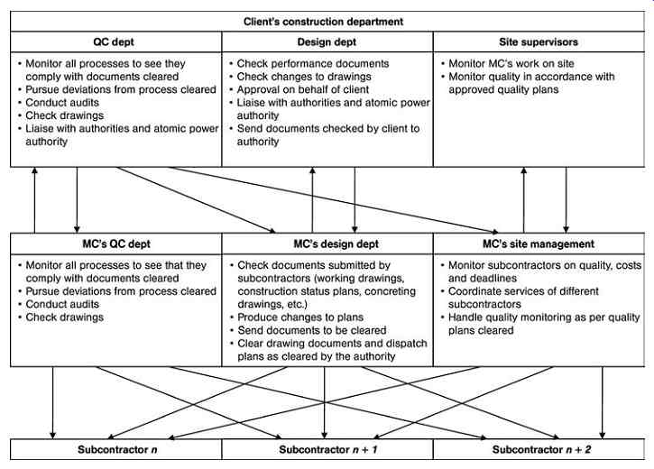
Fig. 16 Tasks and communications paths in project management
Engineering
- Coordinating schedules
- Producing working documents
- Checking subcontractors' working, concreting and installation drawings
- Producing amendments to drawings
Health and safety
- Producing safety at work instructions for use on site
- Checking safety at work on site
- Reporting involved
Contract management
- Drawing up subcontractors' contracts
- Negotiating subcontractors' contracts
- Administrating client's contract
Time scheduling
- Verifying that subcontractors' timetables match project timetables
- Assisting construction department with producing specific coordination timetables
The tasks and communications paths between building management, client and subcontractors are shown in Figure 16.
4.3 Quality assurance
Work on nuclear power plant projects is subject to strict quality assurance requirements.
With the OL3 project, as well as the usual design documents, the designers also produced governing documents on quality assurance which were checked by the client and authorities:
- Work specifications, such as defining specific works, indicating training required
- Quality control plan -- checklists defining what checks are to be conducted and how, and stating who is responsible in each case
Based on these documents, the contractors involved produce work plans, which essentially extrapolate the designers' quality control plans with specific construction aspects (materials, work rates, etc.).
Work plans are produced based on the overall quality assurance system, referencing the underlying performance documents. In substantive terms, they include the working resources and procedures required to perform tasks, the project organization stating who is in charge of performing work and what to do in the event of problems. They also include risk assessments on individual relevant issues.
4.4 Formwork and scaffolding
The average power plant block involves erecting formwork for approx. 500,000m2 of concrete surface.
Precisely in terms of time and costs, it is essential to plan the use of formwork and scaffolding beforehand, as this may affect the performance schedules that the designers produce, such as producing evidence of specific building conditions and additional reinforcement resulting. With complex construction projects, contractors specializing in planning, constructing and providing formwork are involved at an early stage.
The aim in principle is to use formwork and scaffolding elements which are as large as possible and can be used frequently, even if building power plants often involves constructing irregular shapes with variable slab thicknesses and formwork heights.
Making the cupola of a reactor building in a Pressurized water reactor presents particular demands. At the Philippsburg 2 nuclear power plant, the safety enclosure of steel plate under the cupola could not withstand any major stresses, so the concreting load had to be borne by projecting formwork construction (Figure 17).
When building nuclear power plants, slipforming can be used not only for box- and annular-shaped sections such as chimneys, but also in building large freestanding walls, making consoles without further ado or 'slipping in' cutouts. The slipforming method was adopted when making the bioshield at the Krummel nuclear power plant. Using heavy concrete and the many cutouts involved had to be included in considerations.
The OL3 construction project used climbing formwork and/or self-climbing formwork for the more standard building structures such as safety containment and aircraft impact structures (Figure 18).
The compact layout of the nuclear island components calls for using a special single headed formwork. The walls enclosing the UKA, UFA, UKS, UJH and UKE construction modules are separated in some cases by as little as 30-40 cm. These narrow spaces must be kept clear at all times.
The confined working space involved rules out double-headed formwork for whichever module comes later in time. Tying and releasing ties on double-headed formwork on the outside of the enclosing wall would be impossible, as the working space required is not available.
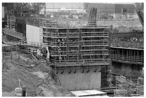
Fig. 18 OL3, UFA building, using large-format wall girder formwork sections
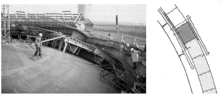
Fig. 17 Cupola formwork, Philippsburg nuclear power plant (left), section
through cupola formwork (right)
The solution adopted in this case was therefore as follows: on the inside of the enclosing wall of the following module, the 'Trio' framework formwork section system by the Peri company is used, which transmits its load via Peri SB framework sections to the lower ceiling or wall-ceiling node point of the lower level. The load is led into the concrete via cast-in tension bars.
The external formwork was made via a special steel formwork section pre-stressed against the outer wall of the preceding building.
The formwork is installed, fixed and removed from the top.
Formwork can be removed once concreting is complete without leaving parts in the join.
4.5 Other particular construction features
In what follows, we will present some other particular features of construction which are particularly characteristic of building nuclear power plants.
4.5.1 Reactor building -- containment
The pre-stressed concrete containment in the OL3 reactor building is made of K60 concrete to Finnish standard BY50 (comparable with C50/60) with a steel liner. The cylindrical section has walls 1.3m thick. The inner steel liner, made of S355J2SN steel, is 6mm thick. The pressure vessel has an internal radius of 23.40m and an outer radius of 24.70m.
To make the cylindrical section of the steel liner, 90 degr. sections 6m high were delivered to the site. These sections were then assembled to form rings 12m high and were lifted into place.
Before being lifted into place, segments were coated with epoxy resin based triple-layer paintwork (basecoat, intermediate coat and topcoat).
Once each liner segment was lifted into place, it was welded to the segment below it. Once it was welded, the reinforcement and tendon sleeve tubes were installed. Tensioning blocks for the horizontal tendons of the containment were spaced 120 degr. apart.
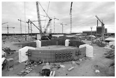
Fig. 19 OL3, Assembling the steel liner on site
Vertical reinforcement joints were made using overlapping or Lenton screwed sockets.
The horizontal reinforcement joints were made mostly with overlaps. The connecting reinforcement for the anchor plates integrated in the steel liner (such as polar crane consoles) was made with back closed stirrups, tying the anchor plates to the stirrups with position sockets.
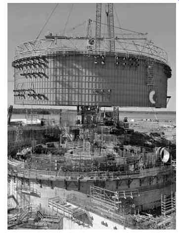
Fig. 20 OL3, lifting in the liner ring
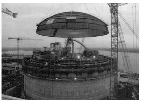
Fig. 21 OL3, lifting in the liner dome
The cylindrical section of the safety containment was shuttered using single-headed self-climbing formwork. The formwork was supported against the structure of the preceding outer containment (APC shell).
One particular structural engineering feature of pressurized water reactors made in Germany is installing the lower steel cap of the steel containment.
The lower section of the spherical steel containment was first made supported on trestles in the spherical concrete segment, so it could be welded on both sides. It was then lowered floating into its final position defined by spacers. Lastly, the cavity remaining was then carefully filled with injection mortar (Figure 22).
4.5.2 Embedded parts
The large number embedded parts involved (a nuclear power plant block may have more than 100,000 anchor plates) calls for a particular feature of planning, such as recognizing collisions in good time and avoiding them, and particular preparations on site to ensure that they can be finished on time in parallel with the formwork and reinforcement work. As well as the anchor plates just mentioned, fitted components include such items as pipes, foundation frames and the frames for Omega water stops, known as Omega frames. These are attached to the formwork or to special support structures, and this must be carried out in such a way as to maintain the tight tolerances in terms of precision location once concreting is complete.
With the OL3 construction project, the anchor plates used to fix components later on are made largely of ferritic steel anchored by headed studs (Figure 23).
These anchor plates arrive on site coated with rust-protection base coat, and are painted in the finishing phase. The plates are painted once again once the load-bearing structure is in place.
Pipe lead-throughs of ferritic or austenitic steel are installed in the first- or second-cast concrete. Fitting them at the second-cast concrete stage means an extra work process before handing over to the mechanical trades, which could delay the latter starting; but the installation quality is generally higher in terms of precision.

Fig. 22 Lower embedded section of safety containment (spherical steel segment)
(left), floating on and under-filling the steel shell (right)
5. Dismantling
Dismantling nuclear power plants represents a major part of nuclear engineering in Germany today.
Dismantling principles
We need to distinguish here between the systems and structures inside the control area -- which could be contaminated or live - and those outside the control area, which are not.
Dismantling the control area, with its contaminated and live sections, breaks down into stages, as follows:
- Shutting the plant down, residual operation, deconstructing the contaminated systems not required for residual operations and making changes to systems and building sections as necessary as takedown proceeds
- Taking down the contaminated, active primary components and the concrete structures which are live from being irradiated for years, and the bioshield in particular
- Demolishing the remaining systems, decontaminating buildings, conducting clearing surveys on buildings and external areas This is aimed at decommissioning the plant as a whole of supervision according to Atomic Energy Act terms.
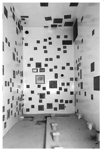
Fig. 23 OL3, Wall view with embedded parts in the UFA building
This is followed by conventional demolition of both the now cleared former control area and the systems and buildings outside the control area.
Weights and costs: For a typical PWR, the demolition and disposal weights estimated in tonnes [t] (internal estimate by HOCHTIEF) are as follows:
- Total power plant: 500,000t
- Control area: 156,500t, of which:
- structural components: 143,000t
- system components: 13,500t
The remaining radioactive waste for final storage is estimated at 4,000 t.
Dismantling costs, excluding residual operation, materials handling and packaging costs - may be estimated roughly at D350m per power plant block.
5.1 Legal foundations and rules
Under the Atomic Energy Act (AtG) §7 - approving plant - para. 3, consent is required to decommission plant and safely contain the ultimately decommissioned plant or demolish plant or sections of plant.
Apart from the Atomic Energy Act, there are other statutory foundations and nuclear regulations to be considered:
- Radiation protection regulations (in German: StrSchV)
- Atomic Energy Act procedural regulations (in German: AtVfV)
- Law on environmental compatibility testing (in German: UVPG) The 'decommissioning guidelines' (guidelines for decommissioning, safe containment and demolition of plant or plant components under §7 of the Atomic Energy Act) are designed to bring the relevant aspects of approval and regulation together. It is also intended to create a common understanding between the Federal Government of Germany and Federal States on proper performance and harmonizing existing views and methods.
There are also BMU guidelines, reactor safety committee (RSK) recommendations, Nuclear Safety Standards Committee rules (KTA), radiation protection committee (SSK) rules and relevant conventional rules to be taken into account when planning and implementing dismantling.
5.2 Decommissioning strategies
There are basically two decommissioning options to choose from when dismantling nuclear power plants:
- Dismantle immediately, as soon as the rundown phase has been completed
- Safe confinement: after the rundown phase, put the nuclear power plant into 'safe confinement' for around 30 years before starting to demolish it
Immediate dismantling
- Demolish all contaminated and active building sections, systems and components immediately
- Prepare and pulverize all radioactive waste for interim or final storage
- Decontaminate and release other remains
- Decontaminate and release building, demolish conventionally Safe confinement
- Demolish all contaminated structures, systems and components outside the containment area immediately
- Reduce control area and prepare and pack radioactive waste involved for interim or final storage.
- Decontaminate and clear other residuals involved
- Clear media (press, TV etc.) if possible
- Leave active structural components (nuclear installations, pressure vessel, bioshield) as installed, seal system interfaces appropriately
- Continue to operate essential systems during safe confinement (ventilation, pressurization, monitoring systems)
- Confine safely for 25-30 years
- Apply for dismantling permit during safe confinement phase (around five years before safe confinement ends)
- Create new infrastructure facilities
- Demolish and clear plant as with immediate demolition
- Timescale:
Establish safe confinement: 5-8 years
Operate in safe confinement mode: 25-30 years
Demolish completely: 8-10 years
In Germany, the only nuclear power plants that have been put into safe confinement are Lingen (KWL) and Hamm-Uentrop (THTR). In the light of experience gathered with dismantling projects to date, the prevailing view today is that starting dismantling as soon as the rundown phase is complete is preferable. The advantages include: the nominal costs of direct dismantling are less than those of safe confinement, plant personnel are still on hand, personnel can continue to be employed and the site can be available to be reused sooner if required. The considerations in favor of safe confinement include reducing potential activity in the plant from radioactive decay, possibly using technical innovations and developments and reducing immediate costs.
5.3 Dismantling phases
The process of decommissioning a nuclear power plant until when it is deregistered under the Atomic Energy Act, including the rundown phase in direct dismantling, takes around 12 years.
We will now describe the individual phases of the process, taking the Stade nuclear power plant (KKS) as our example (Figure 24).
Dismantling phases, using KKS as example:
Phase 1:
- Take down various systems inside and outside control area
- Put different buildings to different uses
- Set up dismantling infrastructure
Phase 2:
- Remove main coolant lines and pumps
- Remove boiler and other large components
- Remove other contaminated system components
Phase 3:
- Make preparations to remove and pack activated building sections and components
- Remove and treat reactor pressure vessel fittings
- Remove reactor pressure vessel
- Remove bioshield
Phase 4:
- Remove remaining system components within control area
- Decontaminate and clear standing structures
- Withdraw from decontaminated areas in stages and seal against recontamination
- Clear site
- Release complete site from Atomic Energy Act monitoring
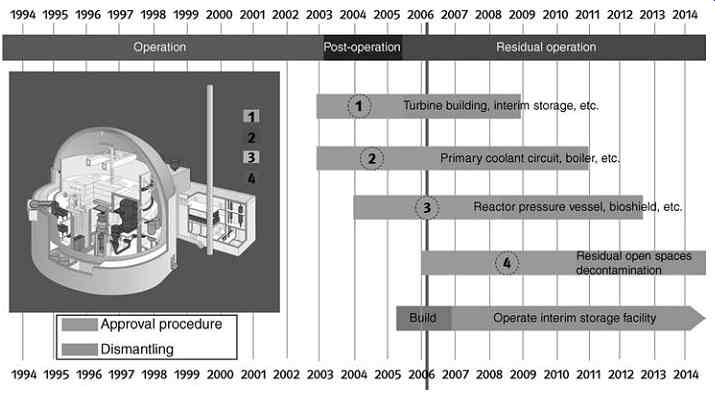
Fig. 24 Stade, dismantling timetable
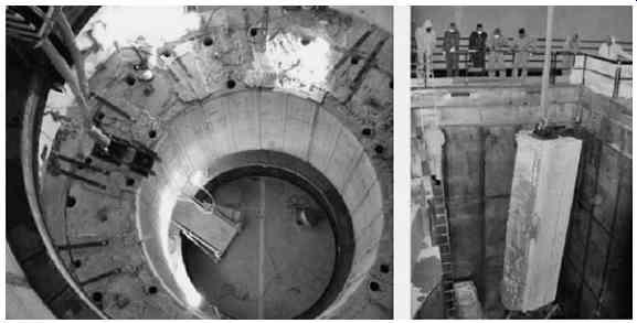
Fig. 25 Removing bioshield using reinforced concrete blocks previously obtained
by using wire saws using HOCHTIEF LAP 60 heavy load anchor as retrofitted load
attachment point
5.4 Individual structural measures involved in dismantling
We list some individual building services below which those involved in dismantling will normally have to carry out:
- Reconstruction measures: fit extra shields, create openings, close openings, take fire precautions
- Strengthen building components to take increased loads due to temporary interim conditions, for example
- Create routes for transport logistics within control area while removing contaminated and activated system components and logistics work retrofitting lifting gear, including creating access roads required
- Removing contaminated concrete structures: establishing depth and extent of contamination levels, cutting off and removing contaminated building surfaces and packing in transport containers
- Removing activated concrete structures (bioshield)
- Measures to prevent building work problems: making safe against falling loads
- Setting up temporary buildings for treating and storing radioactive waste, clearance measurement of system components released completely and unconditionally if classified accordingly
- General service functions such as scaffolding or client providing site electricity supply
5.5 Structural demolition technologies
There are a number of criteria to consider when selecting the right demolition procedure:
- Technical criteria: component materials, geometry and accessibility
- Radiation protection criteria: minimizing aerosol release, primary and secondary waste, avoiding spreading decontamination, ease of decontamination, high level of recyclability of installations used
- Financial criteria: setup costs, equipment costs, operating costs, cutting services
- Strategic criteria: site location, demolition strategy, disposal routes, constraints of materials handling strategy
Demolishing concrete and reinforced concrete structures is often done using wire saws. These have the advantage that large-format blocks can be obtained which can be readily carried away; the drawbacks are that cutting and cooling water may be required and drill holes have to be made to guide the wires in first (Figure 26).
Contaminated concrete layers can be demolished as shown below, depending on the nature and depth of the contamination involved (Table 2, Figure 27).
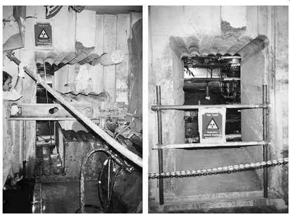
Fig. 26 Making a cut-out in the control area using wire saws and overlapping
core drillings
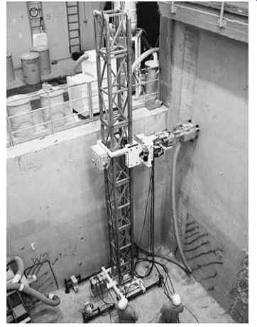
Fig. 27 HOCHTIEF Decon surface milling system in use
==========
Table 2 Methods for decontaminating reinforced concrete sections
Nature and Depth of Contamination --- Method Loose contamination on surface of concrete which can be wiped off Vacuum, brush off, wipe off, wash or spray, apply chemicals Subsurface contamination (has penetrated and attached itself) Grind off, mill over large areas (Figure 27) flame hammer and chisel Deeper contamination into concrete Chisel off conventionally, mill over large areas, combine milling and chiseling.