AMAZON multi-meters discounts AMAZON oscilloscope discounts
GENERAL INFORMATION
1. INTRODUCTION
Of the many decisions that must be made by the designer of a multistory building, probably none is more important than the selection of the vertical transportation equipment-that is, the passenger, service, and freight elevators and the escalators. Not only do these items represent a major building expense, being in the case of a 25-story office building as much as 10% of the construction cost, but the quality of elevator service is also an important factor in a tenant's choice of space in competing buildings.
Although the final decision as to the type of equipment rests with the architect, the factors affecting it are so numerous that the building designer should consult with an elevator expert. This service is available from consultants in the field and from the major elevator and escalator manufacturers.
The function of this Section is to familiarize the architect and engineer with the nature and application of vertical transportation equipment in order to enable them to make preliminary design decisions and interact effectively with consultants.
2. PASSENGER ELEVATORS
This Section is concerned primarily with general purpose traction and hydraulic elevators.
Ideal performance of an elevator installation will provide minimum waiting time for a car at any floor level; comfortable acceleration; rapid transportation; smooth, rapid braking; accurate automatic leveling at landings; and rapid loading and unloading at all stops. The elevator system must also provide quick, quiet operation of doors; good floor status and travel direction indication (both in the cars and at landings); easily operated car and landing call buttons (or other devices); smooth, quiet, and safe operation of all mechanical equipment under all conditions of loading; comfortable lighting; reliable emergency and security equipment; and a generally pleasant car atmosphere.
In addition to passenger satisfaction- oriented service considerations, elevators have architectural design impacts. Cars and shaft way doors must be treated in a manner consistent with the architectural unity of the building.
More important, however, elevator shaftways are major space elements whose integration into a building is a prime factor in composition, as is the design of the elevator lobby.
3. CODES AND STANDARDS
Perhaps more than any other element of construction, elevators are governed by strict installation codes. The definitive resource in the United States is the American Society of Mechanical Engineers' ANSI/ASME Standard A17.1, Safety Code for Elevators and Escalators, the latest version of which should be in every architect's and engineer's working library. The code has legal force in most parts of the United States. Two related standards should be noted. ANSI/ASME Standard A17.3 covers existing elevators and escalators, and Standard A17.4 covers emergency evacuation of passengers from elevators. Some states and municipalities have their own elevator codes (Massachusetts, Wisconsin, Pennsylvania, New York City, Seattle, and Boston, among others) that are generally based upon, but more stringent than, the ANSI/ASME code.
In addition to the elevator code, other construction and installation codes influence elevator work. National Fire Protection Association (NFPA) 101, the Life Safety Code, details certain fire safety requirements; NFPA 70 (the National Electrical Code) governs some of the electrical aspects of elevator construction; and state and local laws can add a multitude of requirements and restrictions bearing on fire safety, emergency power, security concerns, and special accommodations for handicapped persons. Provisions for the disabled are covered by American National Standards Institute (ANSI) A117.1 (Accessible and Usable Buildings and Facilities, a special industry code), by the requirements of the Americans with Disabilities Act (ADA), and, in most locations, by local law.
Like most large industries, the elevator industry is self-regulating and standardized. The National Elevator Industry, Inc. (NEII) publishes standard elevator layouts for traction and hydraulic installations. Elevator consultants and elevator company representatives are normally knowledgeable about all of the codes and standards in force, but this does not relieve the architect-engineer of legal responsibility for the design. Therefore, we strongly recommend that in the preliminary planning stage all pertinent regulations concerning vertical transportation be acquired, reviewed, and understood.
TRACTION ELEVATOR EQUIPMENT
4. PRINCIPAL COMPONENTS
The car, cables, elevator machine, control equipment, counterweights, hoistway, rails, penthouse, and pit are the principal parts of a traction elevator installation. An idea of the functioning and orientation of these items of equipment can be obtained from FIG. 1.
The car is the only item with which the aver age passenger is normally familiar. Some of a building's prestige depends upon proper design of the elevator car. Essentially, the car is a cage of some fire-resistant material supported on a structural frame, to the top member of which the lifting cables are fastened. By means of guide shoes on the side members, the car is guided in its vertical travel in the shaft. The car is provided with safety doors, operating-control equipment, floor level indicators, illumination, emergency exits, and ventilation. It is designed for long life, quiet operation, and low maintenance.
The cables (ropes) that are connected to the crosshead (top beam of the elevator) and carry the weight of the car and its live load are made of groups of steel wires specially designed for this application.
Four to eight cables, depending on car speed and capacity, are placed in parallel. Although multiple ropes are used primarily to increase the traction area on the drive sheaves, they also increase the elevator safety factor-as each rope is normally capable of supporting the entire load. The minimum factor of safety varies from 7.6 to 12.0 for passenger elevators and from 6.6 to 11.0 for freight elevators.
The cables from the top of the car pass over a motor driven cylindrical sheave at the traction machine (grooved for the cables) and then downward to the counterweight.
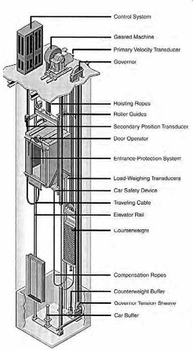
FIG. 1 Components of a geared elevator installation with solid-state control
and motor drive. (Otis Elevator Co.)
The counterweight is made up of cut steel plates stacked in a frame attached to the opposite ends of the cables to which the car is fastened. It is guided in its travel up and down the shaft by two guide rails typically installed on the back wall of the shaft. Its weight equals that of the empty car plus 40% of the rated live load. It serves several purposes: to provide adequate traction at the sheave for car lifting, to reduce the size of the traction machine, and to reduce power demand and energy cost. These advantages come at the cost of having to strengthen the overhead machine room floor, which must carry the additional structural load of the counterweight.
Approximately 75% of the energy expended in lifting a car is returned to the system by regeneration when the car is lowered. Regeneration is the process by which the traction motor becomes a generator when the car is lowered and feeds power back into the electrical system. The unrecovered energy appears as heat, primarily in the machine room. See Sections 43 for a discussion of traction elevator system energy requirements.
To compensate for the hoist rope weight, which becomes an important factor in high-rise elevator installations, cables are attached to the bottom of the car and the counterweight, thus equalizing loads regardless of the cab position. These cables can be seen in FIG. 1.
The elevator machine turns the sheave and lifts or lowers the car. The machine consists of a heavy structural frame on which are mounted the sheave and driving motor, the gears (if any), the brakes, the magnetic safety brake, and certain other auxiliaries.
In many existing installations the elevator driving (traction) motor receives its energy from a separate motor-generator (m-g) set, which is in operation during the period that the particular elevator is available to handle traffic. This m-g set is properly considered a part of the elevator machine, although it may be located some distance from it. In newer installations, solid-state power and control equipment will replace the m-g set, as discussed in Sections 20. A governor, which limits the car to safe speeds, is mounted on or near the elevator machine.
The control equipment is usually divided into three groups:
1. Drive (motion) control is concerned with the velocity, acceleration, position determination, and leveling of the car.
2. Operating control covers car door operation and functioning of car signals, including floor call buttons and all indicating devices.
3. Supervisory control is concerned with group operation of multiple-car installations.
The actual physical devices in these control systems were historically electromechanical, but solid-state devices are used in modern installations.
The indicating and control devices that are seen by the elevator user, including car and hallway buttons, lanterns, and audible devices, are all coordinated into an overall operational control scheme, to provide rapid, safe, and comfortable vertical transportation.
The shaft, or hoistway, is the vertical passage way for the car and counterweights. On its side walls are the car guide rails and certain mechanical and electrical auxiliaries of the control apparatus.
At the bottom of the shaft are the car and counter weight buffers. At the top is the structural platform on which the elevator machine rests. The elevator machine room (which may occupy one or two levels) is usually directly above the hoistway. It contains the traction machine and the solid-state control (or m-g set) that supplies energy to the elevator machine and control equipment. Machinery and control equipment are designed for quiet, vibration-free operation.
5. GEARLESS TRACTION MACHINES
A gearless traction machine consists of a dc or ac motor, the shaft of which is directly connected to a brake wheel and driving sheave. The elevator hoist ropes are placed around this sheave. The absence of gears means that the motor must run at the same relatively low speed as the driving sheave. As it is not economically practical to build motors for operation at very low speeds, a gearless machine is utilized for medium- and high-speed elevators-that is, 500 fpm (2.5 m/s) and above. The motors range from 20 to 400 hp (15 to 300 kW).
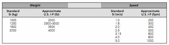
TABLE 1 Elevator Capacity and Speed, Approximate SI and I-P Product Equivalents
Gearless machines are generally utilized for passenger service, with car capacities of 2000 to 4000 lb (907 to 1814 kg), although special cars of up to 10,000 lb (4536 kg) have been built. Below 500 fpm (2.5 m/s), geared machines are used. At this writing, maximum car speeds are 2000 fpm (10 m/s). Faster drives have been developed and will likely play a role in the development of the next generation of very-high-rise buildings.
A gearless traction machine is considered superior to a geared machine because it is more efficient and quieter in operation, requires less maintenance, and has longer life. The decision as to whether these advantages are worth the additional cost involved can be made only after a careful analysis. Generally, a gearless machine is chosen where the rise is more than 250 ft (76 m), and very smooth, high-speed operation is desired. In the intermediate range of rise and speeds (i.e., 150 to 250 ft [46 to 76 m] height and 400 to 500 fpm [2 to 2.5 m/s]), excellent equipment, both geared and gearless, is available.
Because virtually every major elevator company operates internationally, and outside of the United States elevator size and speed are specified in kilograms and meters per second, it is useful to be aware of the SI equivalents for key design variables.
As 1 kg is 2.2 lb and 1 m/s is 196.86 fpm, approximate conversion factors of 2 and 200, respectively, can be used (TABLE 1). SI units shown herein are generally the more precise equivalents.
6. GEARED TRACTION MACHINES
A geared traction machine has a worm and gear interposed between the driving motor and the hoisting sheave ( FIG. 2). The driving motor can therefore be a smaller, cheaper, high-speed unit rather than the large, low-speed unit required by a gearless installation.
The motor used in a geared installation, as in a gearless one, depends upon the type of drive system and may be either dc or ac. Characteristics of the various drive systems and their application are discussed in detail in Sections 15 to 18.
Geared machines are used for car speeds of up to 450 fpm (2.3 m/s) and a maximum rise of about 300 ft (90 m). With an appropriate drive and control system, a geared traction machine can give almost the same high-quality, accurate, smooth ride as is available from a gearless installation.
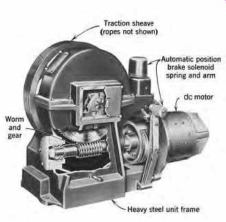
FIG. 2 Cutaway of a typical dc geared traction elevator machine. Note the
grooves for multiple ropes in the traction sheave. (Photo courtesy of Schindler
Elevator Corp.)
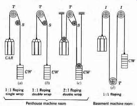
FIG. 3 Elevator roping and sheave arrangements. (a) Basic single-wrap rope
arrangement. In (b) and (c), the rope passes over traction sheave T and sheave
S, doubles back over T, and then extends past S to the counterweight CW. This
double-wrap arrangement provides additional traction at the drive sheave. (d)
Roping arrangement for a basement machine room.
7. ARRANGEMENT OF ELEVATOR MACHINES, SHEAVES, AND ROPES
The simplest method of arranging vertical travel of a car is to pass a rope over a sheave and counterbalance the weight of the car by a counterweight. Then, rotating the sheave makes the car move up or down and requires very little energy to do so. This is essentially the scheme that is used on a majority of high-speed passenger elevators, as illustrated in FIG. 3a.
When the four or more supporting ropes merely pass over the sheave (T) and connect directly to the counterweights, the lifting power is exerted by the sheave through the traction of the ropes in the parallel grooves on the sheave. This system is referred to as the single-wrap traction elevator machine. The function of the sheave (S) is merely that of a guide pulley; it is called the deflector sheave.
The arrangement shown in FIG. 3b is called double-wrap 1:1 roping. It provides greater traction than the single-wrap arrangement and is used in many automatic high-speed installations.
A 1:1 roping arrangement ( FIG. 3a, b, d) gives no mechanical advantage. The 2:1 roping ( FIG. 3c) has a mechanical advantage of 2, which permits use of a high-speed, low-power (and, there fore, lower-cost) traction machine. This arrangement is used for a wide variety of installations varying from medium-speed (500 to 700 fpm [2.5 to 3.6 m/s]) gearless passenger elevators to low speed, heavy-duty freight elevators.
In types a, b, and c in FIG. 3, the elevator machines are located in a machine room penthouse at the top of a hoistway. If, for architectural or other reasons, it is desired to eliminate the penthouse, a basement machine room can be used with the roping shown in FIG. 3d. This arrangement uses geared traction equipment with speeds of up to 400 fpm (2.0 m/s). All the illustrated ropings are applicable to the full range of car capacities.
8. SAFETY DEVICES
The main brake of an elevator is mounted directly on the shaft of the elevator machine (see FIG. 2). The elevator is first slowed by dynamic braking of the motor, and the brake then operates to clamp the brake drum, thus holding the car still at the floor.
A dual safety system, designed to stop an elevator car automatically before its speed becomes excessive, is normally used. The device that acts first is a centrifugal governor or an electronic speed sensor that cuts off the power to the traction motor and sets the brake in the event of a limited overspeed. This usually stops the car. Should the speed still increase, the governor actuates two safety rail clamps, which are mounted at the bottom of the car, one on either side. They clamp the guide rails by wedging action, bringing the car to a smooth stop ( FIG. 4).
Oil or spring buffers are usually placed in the elevator pit. Their purpose is not to stop a falling car but to bring it to a somewhat cushioned stop if it overtravels the lower terminal. If a car overtravels (down or up), travel sensors deenergize the traction motor and set the main brake. Safety arrangements under emergency conditions (fire or power failure) are discussed in Sections 45 and 31.46.
FIG. 4 Elevator safety devices. The governor or velocity transducer regulates
overspeed, clamping the safety trip rope and releasing the safety jaws, which
exert a constant retarding force on the car rails, thus bringing the car to
a gradual and safe stop. (Photo courtesy of Schindler Elevator Corp.)
HYDRAULIC ELEVATORS
9. CONVENTIONAL PLUNGER TYPE HYDRAULIC ELEVATORS
The elevators discussed in the preceding sections are traction types; that is, they are raised and lowered as a result of friction that transmits force from the drive mechanism through cables attached to or passing under the car. These cables in turn are raised and lowered by a motor-driven traction sheave. In contrast, the conventional hydraulic (or plunger) elevator car is raised and lowered by means of a movable rod (plunger) rigidly fixed to the bottom of the car. The absence of cables, drums, traction motors, elaborate controllers, safety devices, and penthouse equipment makes this system inherently inexpensive and often the indicated choice for low-speed (up to 200 fpm [1 m/s]), low-rise (up to 65 ft [20 m]) applications, where construction of the plunger pit does not present difficulties, and/or the absence of a penthouse is desirable.
The first hydraulic elevators used water as the system fluid, supplied at sufficient pressure from roof-mounted water tanks. The tanks were kept full by a building's water pumps. All hydraulic elevators today use oil and obtain their motive power from a sealed oil-piping circuit powered by an oil pump.
The components of a typical hydraulic unit are shown in FIG. 5. This system operates the same way as a hydraulic automobile jack. Oil from a reservoir is pumped under the plunger, thereby raising it and the car. The pump is stopped during down ward motion, the car being lowered by gravity and controlled by the action of bypass valves, which also control the positioning of the car during upward motion. Control systems that are normally used are similar to those for traction elevators-for example, collective and selective collective approaches.
Similarly, door arrangements are the same as in traction elevators-that is, single-slide, center opening, and two-speed arrangements. Automatic leveling is readily available and is standard on all units with automatic controls.
From a design and construction perspective, the major advantage of hydraulic units is the absence of an overhead machine room, a penthouse, and traction equipment. As shown in FIG. 5, only the guide rails project above the car and, if these are camouflaged, the impression of a freestanding elevator car is given. This effect can be used to good advantage inside large, open spaces such as in shopping malls and stores; when combined with glass-enclosed, observation-type cars, the effect can be striking (see Figs. 8 and 9).
Additional advantages of hydraulic elevators over traction units include:
• The elevator load is carried by the ground and not by the structure. In contrast, traction units place a large structural load on the penthouse and machine room floors and on overhead steel as well.
• The hoistway is smaller due to the absence of a counterweight and its guide rails.
• Cars can be lowered manually by the operation of oil valves. This is particularly useful and important in the event of control equipment failure or power outage.
• There is essentially no limit to the load that can be lifted.
FIG. 5 Phantom view of a conventional "holed" hydraulic elevator, so called because the elevator car rests on a hydraulically activated steel plunger that descends into a hole in the ground. The hole is actually a buried hollow steel cylinder into which oil is pumped, under pressure, to raise the car. The oil pump is inside the fluid tank. (Illustration courtesy of Otis Elevator Co.)
The major disadvantage of a standard hydraulic elevator is its operating expense. Because it is not counterweighted, it requires a relatively large motor to drive the oil pump, and all the energy is l lost in heat (see TABLE 2). For an example of this operating cost disadvantage, consider a 3500-lb (1588-kg), 125-fpm (0.6-m/s) hydraulic elevator in a department store. Such a unit requires a 40-hp (30-kW) motor. Assuming the unit to be in operation 10 hours a day, 6 days a week, and assuming a normal 60% time-in-operation figure, gives (remembering that the motor operates only in the up direction):
energy 40hp
0.82eff f f
0.746kW hp 60 used/day =× p
× % % ××
=
10h 110kWh 1 2 At an electricity cost of $0.08/kWh, monthly energy cost 110 6days week 4.33weeks m
=
×
× ont o o h $0.08
$229 month
×
=/ $229
=========

TABLE 2 Comparative Energy Use of Various Motion Control Arrangements
Energy Use | Relative Use Hydraulic elevators 10 UMV motion control; geared dc traction motor 7-7.5 UMV motion control; gearless dc traction motor 6-6.5 Thyristor control; geared dc traction motor 5-5.5 Thyristor control; gearless dc traction motor 4-4.5 Variable-voltage variable-frequency control, ac traction motor 2.5-3.0
=========
Compare this to the calculated (Section 43)
monthly energy cost for a 3500-lb (1588-kg), 600 fpm (3-m/s) traction car of $72 when using solid state equipment and $126 with an m-g set power supply, to get an appreciation of the value of a counterweight.
Other disadvantages of hydraulic units as com pared to traction units include:
• They are limited to low-rise, low-speed applications.
• Ride quality is inferior to that of a good traction unit, although it is entirely acceptable for residential, mercantile, and industrial applications.
• Because oil viscosity changes with temperature, the ambient temperature of the space containing the pump and the oil storage tank must be controlled to maintain ride quality and performance.
• The high inrush current required by the pump each time it starts (which is every time the elevator travels upward) necessitates a "stiff" power supply to avoid problems of flickering lamps and other undesirable line-voltage fluctuations.
• Noise from the pump and motor plus piping noise can be disturbing. This problem can be ameliorated by skillfully locating the pump mechanism (which can be placed up to 50 ft [15 m] from the elevator shaft).
Plunger-type hydraulic elevators have experienced some disfavor because of problems caused by oil seepage into the ground. The plunger travels in a buried steel casing that, despite excellent butyl or other liquid-tight coatings, can corrode after an extended period and leak oil. In most locations, this will violate regulations dealing with groundwater pollution. Because repair of such an oil leak is expensive and entails extended elevator outage, other arrangements (as detailed in the next two sections) have come into increasing use.
Hydraulic elevators are best applied to low speed, low-rise applications such as office buildings and residential buildings up to four stories in height, low-rise department stores, malls, basement and parking garage shuttles, theater elevators, and stage lifts and freight applications of all sorts-in particular, those intended for very heavy loads. Another very useful application is for the use of handicapped persons who cannot use escalators or negotiate stairs. A typical layout and dimensional data for standard plunger units are given in FIG. 6, along with capacities and application recommendations.
10. HOLE-LESS HYDRAULIC ELEVATORS
Where drilling a plunger hole presents difficulties, a hydraulic installation using a telescoping plunger or a roping arrangement can be used. The telescoping jack design is shown schematically in FIG. 7 in a single-jack arrangement. As this causes a lateral stress in the building due to the cantilevered car, a dual-jack arrangement is used more frequently. When supported on both sides, as shown in FIG. 8, all of the vertical elevator load is transferred directly to the ground. The telescoping jack, in which all sections move simultaneously, is more complex than a simple plunger unit and requires more maintenance, although maintenance is simplified by the fact that the entire length of the jack is readily accessible. The ride with the telescoping jack arrangement is not as smooth as that on a straight plunger elevator due to the simultaneous movement of the jack's telescoping sections, causing a degree of jerk.

FIG. 6 Typical dimensional, capacity, and layout data for a conventional
plunger-type hydraulic elevator. Door systems are single slide (SS) or center
opening (CO). The car can be used as a viewing-type unit by utilizing a glass
wall at the back of the car. (Extracted with permission from published data
of Schindler Elevator Corp.)
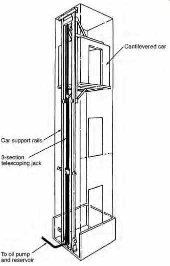
FIG. 7 Hole-less hydraulic elevator driven by a single telescoping jack.
The cantilevered car exerts a lateral structural load on the building. This
arrangement is used less than the two-jack mechanism shown in FIG. 8. (Courtesy
of Otis Elevator Co.)
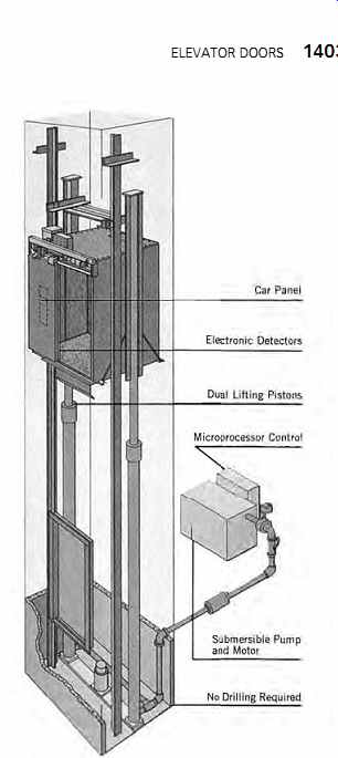
FIG. 8 Dual-jack hole-less hydraulic elevator. The balanced vertical load
is borne by the ground only, with no building component. The unit illustrated
is suitable only for a low-rise (two-stop) installation, with a car weighing
no more than 2500 lb (1134 kg). (Courtesy of Otis Elevator Co.)
11. ROPED HYDRAULIC ELEVATORS
The roped hydraulic arrangement is simpler than the telescoping plunger unit because it uses only a single moving jack section compared to two or even three in a telescoping unit for the same rise.
It accomplishes this by using 2:1 roping, which means that the car travels twice as far as the piston. This is accomplished by passing the rope over a pulley in the piston crosshead. One end of the rope is attached to a fixed point in the pit below the car, and the other end is attached to the base of the car ( FIG. 9). The piston (plunger, jack) lifts the cross head, which in turn lifts the car twice as far.
The arrangement shown in FIG. 9 uses a single jack and a cantilevered car. Other arrangements use two jacks to eliminate the lateral building load ( FIG. 10). A 2:1 roping is standard in the United States. The simplicity and reliability of the single- or double-jack roped arrangement has made it by far the most common choice for low-rise, light- to medium-duty hydraulic elevators. Because it is a roped unit, it is equipped with a slack-rope safety in addition to the other safeties used on direct connected hydraulic systems.
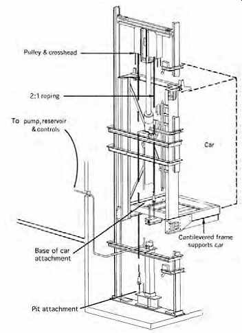
FIG. 9 Low-rise residential-type elevator of the roped hydraulic type. The
cantilevered car is lifted by cables from the cable cross head, which is in
turn lifted (and lowered) by the single-section telescoping piston (jack).
The 2:1 roping arrangement lifts the car twice as far as the piston travels.
The power unit, which includes the oil tank, pumps, and control, is usually
mounted at the lower level.
Control is automatic, including automatic leveling. Depending upon the specific design, the car is a 700 to 750-lb (318 to 340-kg), 30 to 36-fpm (0.15 to 0.18-m/s) unit, normally with a single-story rise. The hatchway is 16 to 26 ft 2 (1.5 to 2.4 m2), with the larger size used for a car intended to accommodate a wheelchair. (Courtesy of CemcoLift, Corbett Elevator Co.)
PASSENGER INTERACTION ISSUES
12. ELEVATOR DOORS
The choice of a car and hoistway door affects the speed and quality of elevator service considerably.
Doors for passenger elevators are power-operated and are synchronized with the leveling controls so that the doors are fully opened by the time a car comes to a complete stop at a landing. The closing time, however, varies with the type of door and the size of the opening. For safety reasons, the kinetic energy of an automatic door is limited to 7 ft-lb (9.5 N m) and its closing pressure to 30 lb (13.6 kg). To provide the fastest closing within this energy limitation, a center-opening door is used.
Also, to reduce passenger transfer time and avoid discomfort, a clear opening of 3 ft, 6 in. (1.07 m) is used in most commercial installations, which permits simultaneous loading and unloading without undue passenger contact. (Some consultants feel that simultaneous passenger transfer is practical only with a 48-in. [1.2-m] clear opening; FIG. 11). When an opening narrower than 36 in.
(915 mm) is used, loading is delayed until unloading is complete, and the speed and quality of ser vice are thereby markedly reduced. Such small doors are applicable only in residential or small, light-traffic buildings. Available door types are shown in FIG. 12.
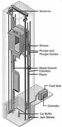
FIG. 10 For heavier loads than can be readily handled by the cantilevered
car in a single-jack design ( FIG. 9), a balanced dual jack (cylinder) is used,
as seen in this phantom view. This design, which can accomplish somewhat higher
rise than a single-jack design, in addition to carrying much heavier loads,
also requires a larger shaftway to accommodate the second cylinder and rails.
(The second pulley and crosshead are omitted for clarity in the drawing.) (Courtesy of Otis Elevator Co.)
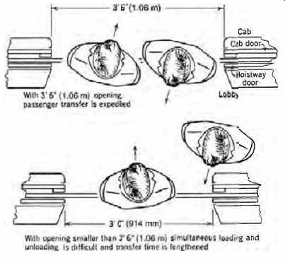
FIG. 11 Transfer of passengers with door openings of different widths. With
openings smaller than 3 ft, 6 in. (1.07 m), simultaneous loading and unloading
is difficult and transfer time is lengthened. With a 42-in. (1.07-m) opening,
large people or people with bulky outerwear may brush against each other in
passing. For complete isolation of passengers, a 48-in. (1.22-m) opening may
be necessary.

FIG. 12 Typical hoistway doors and applications. (a) Single-slide door, 24
to 36 in. (610 to 914 mm) wide, for small commercial building or residential
use. (b)
Standard commercial 42-in. (1.07-m) center-opening door for office building use or 48 to 60-in. (1.22 to 1.52-m) center-opening door for hospital or service car. (c) Two speed, 42-in. (1.07-m) general commercial use door. (d) Two-speed, center-opening, 60-in. (1.52-m) department store door for freight, passenger, and nonautomatic service.
A two-speed door design is used where space conditions dictate or where a wide opening is required. The term two-speed reflects the fact that d the two halves of the door must travel at different speeds to complete their travel simultaneously (see FIG. 12c).
Installations can be equipped with an electronic sensing device that detects passengers in a wide area on the landing in front of the car door rather than only directly in the door's path.
Such detection, often accompanied by an audible signal, causes the car door to remain open for a predetermined length of time or a closing door to reverse. These devices are particularly useful in installations where passengers cannot approach the entrance or cannot enter the car quickly- for example, riders with baggage or holding children, people in wheelchairs, and employees moving bulky objects such as beds or carts in hospitals or wheeled objects in office and industrial facilities.
All automatic elevators, regardless of whether or not equipped with detection beams, are required by ANSI to have a safety edge device on the car doors that causes the car and hoistway doors, which operate in synchrony, to reopen when the safety edge meets any obstruction. Some car doors are arranged to "nudge" when almost closed and/ or after a specific time period. ADA requirements for elevators are discussed in Sections 14.
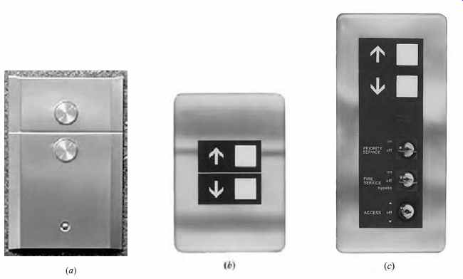
FIG. 13 Typical hall stations. (a) Simple pushbutton station with an illuminated
ring on each button to indicate call registration.
(b) Large buttons show travel direction in addition to lighting up to indicate call registration. (c) Expanded hall stations may incorporate priority, emergency, or secure access controls as shown. (Photos courtesy of Otis Elevator Co.)

FIG. 14 Typical hall lanterns. (a) The top section is green and lights when
a car approaches, indicating up travel. The bottom section is red, and when
lighted indicates an approaching down car. (b) The lantern shows travel direction
and present car location. (Photos courtesy of Otis Elevator Co.)
13. CARS AND SIGNALS
The primary area where the architect has a generally free hand in choosing equipment relates to the decor of the cars and the selection of hallway and car signals. A typical elevator specification is functional and describes the intended operation of the equipment, while usually including an amount to cover decor of the cars. The type and functions of signal equipment are also specified, but finish and styling are optional. Car interiors may be finished in wood paneling, plastic (Micarta or Formica), stainless steel, or almost any material desired.
Floors may be tile, wood, or carpeting, as selected.
Illumination may be from ceiling fixtures, coves, or a completely illuminated luminous ceiling of standard or special design. For each bank of elevators, it is wise to furnish at least one set of wall mats to protect wall finishes when cars are being used to move tenant furniture. This is especially important where no separate service car has been provided.
Car and hallway signals and lanterns should be designed to fulfill their basic functions, consider the needs of the handicapped, and coordinate with the decor of the cars and corridors.
(For a discussion of the car control panel, see Sections 27.) The hall buttons should indicate the desired direction of travel and by visual means confirm that a call has been placed. The hall lantern located at each car entrance must visually indicate the direction of travel of an arriving elevator and preferably its present location (Figs. 13 and 14). An audible signal should announce a car's imminent arrival. This feature allows waiting passengers to move to the next arriving car in a bank, which speeds service. Hall stations can be equipped with special switches for fire, priority, and limited-access service, as required.
Within the car, travel direction and present location can be indicated either with separate fixtures or by indicators built into the car panel. Most manufacturers can provide voice synthesizers built into the car panel that announce the floor, direction of travel, and any other desired message such as safety or emergency messages.
14. REQUIREMENTS FOR THE DISABLED
Elevator manufacturers follow ADA (the Americans with Disabilities Act) requirements as a minimum, and may add additional conveniences for the disabled to meet specific building design intent or local codes. No planning should begin until the project architect has assembled and reviewed all applicable codes and standards. Information regarding elevator accessibility requirements (which reference ASME A17.1-1990, Safety Code for Elevators and Escalators) may be found on the United States Access Board's Web site (http://www.access-board.gov/).
The primary physical limitations addressed by ADA are those of ambulation, sight, and hearing.
Thus, to ease access for passengers in wheelchairs (or with walking aids), the ADA requires excellent car leveling, 36-in. (915-mm) minimum clear door opening (42 in. [1.1 m] recommended), delayed door closing, detection beams that reopen the door without contact on sensing a passenger in the door opening, inside car dimensions that permit turning a wheelchair, buttons and emergency controls within easy reach, and appropriate car furnishings.
For those with sight impairment, the ADA requires audible signals in addition to easily seen and recognized visual ones, both in the car and at landings, to indicate call registration, car approach, car landing, direction of travel, floor, car position, and so on. In this connection, a voice synthesizer is of invaluable assistance. In addition, Braille plates adjacent to car floor buttons and large, easily recognizable symbols adjacent to passenger-controlled emergency controls are to be used. Hearing-impaired passengers are assisted by the large visual signals required for sight-impaired passengers. In addition, call buttons must visually indicate that a call has been placed and likewise indicate when the call has been answered. Many of these ideas also make life easier for all passengers. A note of caution: Delayed door closing may increase overall travel time appreciably.
In buildings with substantial traffic peaks, it may be necessary to designate one or more specific elevators for use by the disabled during peak periods.
The verbatim requirements of the ADA as stated in the Federal Register, Vol. 56, No. 144, July 26, 1991, are presented in FIG. 15, with accompanying illustrations as they appear in the Federal Register. References to illustrations within this figure are to the Federal Register figure numbers.
===========
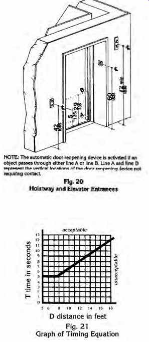
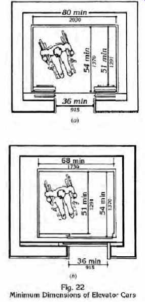
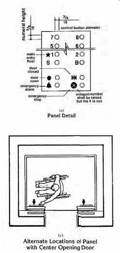
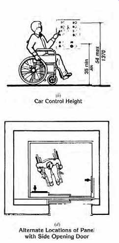
FIG. 15 ADA requirements for elevators extracted from the Federal Register,
July 26, 1991 (these are current with the ADA Accessibility Guidelines for
Buildings and Facilities as amended through 2002).
ADA Accessibility Guidelines for Buildings and Facilities
4.10 Elevators
4.10.1 General.
Accessible elevators shall be on an accessible route and shall comply with 4.10 and with the ASME A17.1-1990. Safety Code for Elevators and Escalators. Freight elevators shall not be considered as meeting the requirements of this section unless the only elevators provided are used as combination passenger and freight elevators for the public and employees.
4.10.2 Automatic Operation. Operation shall be automatic. Each car shall be equipped with a self- leveling feature that will automatically bring the car to floor landings within a tolerance of 1 2 in. (13 mm) under rated loading to zero loading conditions. This self- leveling feature shall be automatic and independent of the operating device and shall correct the overtravel or undertravel.
4.10.3 Hall Call Buttons.
Call button in elevator lobbies and halls shall be centered at 42 in. (1065 mm) above the floor. Such call buttons shall have visual signals to indicate when each call is registered and when each call is answered.
Call buttons shall be a minimum of 3/4 in. (19 mm) in the smallest dimension. The button designating the up direction shall be on top. (See Fig. 20.) Buttons shall be raised or flush. Objects mounted beneath hall call buttons shall not project into the elevator lobby more than 4 in. (100 mm).
4.10.4 Hall Lanterns. A visible and audible signal shall be provided at each hoistway entrance to indicate which car is answering a call. Audible signals shall sound once for the up direction and twice for the down direction or shall have verbal annunciators that say "up" or "down". Visible signals shall have the following features:
(1) Hall lantern fixtures shall be mounted so that their centerline is at least 72 in. (1830 mm) above the lobby floor. (See Fig. 20.)
(2) Visual elements shall be at least 21 2 in. (64 mm) in the smallest dimension.
(3) Signals shall be visible from the vicinity of the hall call button (see Fig. 20). In- car lanterns located in cars, visible from the vicinity of hall call buttons, and conforming to the above requirements, shall be acceptable.
4.10.5 Raised and Braille Characters on Hoistway Entrances. All elevator hoistway entrances hall have raised and Braille floor designations provided on both jambs. The centerline of the characters shall be 60 in. (1525 mm) above finish floor. Such characters shall be 2 in. (50 mm) high and shall comply with 4.30.4. Permanently applied plates are acceptable if they are permanently fixed to the jambs (see Fig. 20).
4.10.6 Door Protective and Reopening Device. Elevator doors shall open and close automatically. They shall be provided with a reopening device that will stop and reopen a car door and hoistway door automatically if the door becomes obstructed by an object or person. The device shall be capable of completing these operations with out requiring contact for an obstruction passing through the opening at heights of 5 in. and 29 in. (125 mm and 735 mm) above finish floor (see Fig. 20). Door reopening devices shall remain effective for at least 20 seconds. After such an interval, doors may close in accordance with the requirements of ASME A17.1-1990.
4.10.7 Door and Signal Timing for Hall Calls.
The minimum acceptable time from notification that a car is answering a call until the doors of that car start to close shall be calculated from the following equation:
T = D/(1.5 ft/s) or T = D/(445 mm/s) where T total time in seconds and D distance (in feet or millimeters) from a point in the lobby or corridor 60 in. (1525 mm) directly in front of the farthest call button controlling that car to the centerline of its hoistway door (see Fig. 21). For cars with in- car lanterns, T begins when the lantern is visible from the vicinity of hall call buttons and an audible signal is sounded. The minimum acceptable notification time shall be 5 seconds.
4.10.8 Door Delay for Car Calls. The mini mum time for elevator doors to remain fully open in response to a car call shall be 3 seconds.
4.10.9 Floor Plan of Elevator Cars. The floor area of elevator cars shall provide space for wheel chair users to enter the car, maneuver within reach of controls, and exit from the car. Accept able door opening and inside dimensions shall be as shown in Fig. 22. The clearance between the car platform sill and the edge of any hoistway landing shall be no greater than 11 4 in. (32 mm).
4.10.10 Floor Surfaces. Floor surfaces shall comply with 4.5.
4.10.11 Illumination Levels. The level of illumination at the car controls, platform, and car threshold and landing sill shall be at least 5 foot candles (53.8 lux).
4.10.12 Car Controls. Elevator control panels shall have the following features:
(1) Buttons. All control buttons shall be at least 3 4 in. (19 mm) in their smallest dimension. They shall be raised or flush.
(2) Tactile. Braille, and Visual Control Indicators. All control buttons shall be designated by
Braille and by raised standard alphabet characters for letters, Arabic characters for numerals, or standard symbols as shown in Fig. 23a, and as required in ASME A17.1-1990. Raised and Braille characters and symbols shall comply with 4.30. The call button for the main entry floor shall be designated by a raised star at the left of the floor designation (see Fig. 23a), and as required in ASME A17.1-1990. Raised and Braille characters and symbols shall comply with 4.30. The call button for the main entry floor shall be designated by a raised star at the left of the floor designation (see Fig. 23a). All raised designations for control buttons shall be placed immediately to the left of the button to which they apply. Applied plates, permanently attached, are an acceptable means to provide raised control designations. Floor buttons shall be provided with visual indicators to show when each call is registered. The visual indicators shall be extinguished when each call is answered.
(3) Height. All floor buttons shall be no higher than 54 in. (1370 mm) above the finish floor for side approach and 48 in. (1220 mm) for front approach. Emergency controls, including the emergency alarm and emergency stop, shall be grouped at the bottom of the panel and shall have their centerlines no less than 35 in. (890 mm) above the finish floor (see Fig. 23a and b).
4.10.13 Car Position Indicators. In elevator cars, a visual car position indicator shall be pro vided above the car control panel or over the door to show the position of the elevator in the hoist way. As the car passes or stops at a floor served by the elevators, the corresponding numerals shall illuminate, and an audible signal shall sound.
Numerals shall be a minimum of 1 2 in. (13 mm) high. The audible signal shall be no less than 20 decibels with a frequency no higher than 1500 Hz.
An automatic verbal announcement of the floor number at which a car stops or which a car passes may be substituted for the audible signal.
4.10.14 Emergency Communications. If pro vided, emergency two- way communication systems between the elevator and a point outside the hoistway shall comply with ASME A17.1- 1990. The highest operable part of a two- way communication system shall be a maximum of 48 in. (1220 mm) from the floor of the car. It shall be identified by a raised symbol and lettering complying with 4.30 and located adjacent to the device. If the system uses a handset then the length of the cord from the panel to the hand set shall be at least 29 in. (735 mm). If the system is located in a closed compartment the compartment door hardware shall conform to 4.27, Controls and Operating Mechanisms. The emergency inter-communication system shall not require voice communication.
===========
ELEVATOR CAR CONTROL
15. DRIVE CONTROL
The movement of an elevator car and all of its parts is controlled by three different systems that combine and interact to provide a unified control system.
The supervisory system controls a bank of elevators as a group and dictates which car answers which call. The operational control system determines when l and where physical motion of a car and its doors should occur. This system deals with the operation of the car doors and the integration of car buttons, lanterns, and passenger-operated devices into the overall control and indicating system. The operating control system passes information about car and door control to the motion control system (also known l as drive control). Motion control determines the car's acceleration, velocity, braking, leveling, and regenerative braking, plus all aspects of door motion.
Elevator car control is separate and distinct r from the control system that governs the functioning of a group of cars acting as a system. That arrangement is generally designated the supervisory system and is discussed separately.
Elevator car acceleration and deceleration are accomplished by controlling the speed of the motor that drives the elevator traction machine. This speed control can be accomplished in a number of ways, all of which are in use in elevator installations. They are:
• Thyristor control of an asynchronous (squirrel cage) ac traction motor
• Thyristor control of a dc traction motor
• Motor-generator (m-g) set control of a dc traction motor (Ward-Leonard system)
• Variable-voltage, variable-frequency (VVVF) control of an asynchronous ac traction motor
Rheostatic control of single and multispeed ac motors is essentially obsolete and therefore is not discussed. Each system is described briefly in the following sections, and applicability, advantages, and disadvantages are noted.
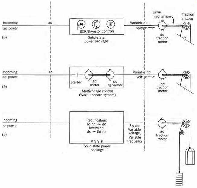
FIG. 16 Arrangement of electric speed-control equipment for elevator drives.
(a) Solid-state, silicon-controlled rectifier (SCR) thyristor control produces
variable-voltage dc and finds application in good-quality new and retrofit
medium- and high-speed installations.
(b) The traditional Ward-Leonard (m-g) system, which produces finely controlled, variable-voltage dc. This is the system in use today in the vast majority of existing high-quality installations. (c) Variable-frequency (VVVF) ac is energy-efficient, highly accurate, and applicable to all types of installations.
16. THYRISTOR CONTROL, AC AND DC
(a) ac
High-power transistors make accurate speed control of inexpensive ac squirrel-cage motors practical by the simple expedient of supplying carefully regulated variable voltage to the motor. The resultant speed control is smooth and stepless, making it applicable to passenger elevator installations. However, the high motor slip caused by the constant frequency of the variable-voltage ac supply causes large thermal losses with resultant low operating efficiency. In addition, the "chopper," which is used to provide the necessary voltage control, introduces undesirable harmonics into the power system in considerable quantity. These harmonics cause undesirable radio noise and can cause system component overheating. Finally, the system's low power factor increases line losses and necessitates increased feeder sizes.
As a result, this option, which is applicable to low and mid-rise passenger service (maximum rise 250 ft [76 m] and maximum car speed of 350 fpm [1.8 m/s]), using geared machines has been largely replaced by VVVF control.
(b) dc
Excellent ride quality can be had by utilizing the dc version of thyristor control (see FIG. 16a) to supply variable voltage to a dc traction motor. This arrangement provides the high-quality ride and leveling characteristic of dc drives and removes the rise and speed limitations of its ac counterpart, but not the system's inherent low power factor, heavy line harmonics, and high machine room thermal losses. Line harmonics can be sharply reduced by the use of power line filters. This control system is widely used today, with both geared and gearless traction machines as applicable, for installations of all rises and car speeds. Its extremely smooth ride makes it one of the three systems of choice in high quality construction. The other two systems are the traditional Ward-Leonard variable-voltage dc system and the VVVF ac system.
17. VARIABLE-VOLTAGE DC MOTOR CONTROL
Before the development of electronic motor control, the only practical way of obtaining the precise motor speed control necessary for smooth, stepless elevator operation was to provide a vari able dc voltage to a dc traction motor. This variable dc voltage was obtained from an auxiliary m-g set comprising an ac motor and a dc generator. This arrangement (see FIG. 16b) is known as a Ward-Leonard system or as a unit-multi-voltage (UMV) drive.
Although this arrangement has disadvantages, it is a classic high-quality elevator drive arrangement and is found in the vast majority of better-quality geared and gearless installations built before 1990. The disadvantages of this system-low overall efficiency, expensive machines, high thermal losses in machine rooms, high maintenance costs for three rotating machines, and high noise levels-were, until the development of a practical VVVF system, accepted as the price of a system that operated faultlessly, with great accuracy at all speeds, and for long periods of time given proper maintenance. As noted previously, it is today still one of the three principal drive control systems being used in new installations. Its principal advantage over VVVF control is that it is "forgiving" of a less than ideal building power supply.
In modernization work, buildings with existing Ward-Leonard systems are frequently converted to solid-state dc thyristor control. This change maintains the excellent ride characteristics of variable voltage dc traction machine installations while improving system performance by replacing the auxiliary m-g set with a low-loss, low-maintenance, quiet, solid-state thyristor drive control.
18. VARIABLE-VOLTAGE, VARIABLE FREQUENCY AC MOTOR CONTROL
This system (see FIG. 16c), which is entirely solid-state, is (in the opinion of many elevator professionals) the drive system of choice for all high-quality new installations of any speed or rise. The system consists of a rectifier, which changes the incoming ac to dc, and an inverter, which creates variable-voltage, infinitely variable frequency, three-phase ac from the (rectified) dc.
This ac is then applied to a standard squirrel-cage ac motor, which operates essentially at the speed corresponding to the frequency of the input. By maintaining a constant voltage-to-frequency ratio input to the traction motor, it is possible to pro vide continuously variable, highly accurate speed control at extremely high efficiencies throughout the full speed range of the motor. This is precisely what is required for high-quality geared and gear less installations, without the energy losses associated with the auxiliary m-g set associated with UMV control. The VVVF speed control system eliminates most of the disadvantages of the solid state thyristor control system and has the following characteristics:
• Overall system efficiency is high at all motor speeds.
• Traction motors are economical single-speed squirrel-cage ac.
• Motors are 10% to 15% smaller than those of other drive systems.
• System power factor is close to unity.
• Line harmonics are lower than with thyristor controls.
• Speed control and leveling are equal to dc traction motor control.
• Equipment is 98% solid-state, thus requiring minimum maintenance.
• Electric energy use and peak loads are reduced, thus reducing electric billings by up to 35%.
• The system is applicable to all rises and speeds.
• Machine rooms are smaller, cooler, and quieter than those using Ward-Leonard UMV controls.
The preceding discussion can be summarized with tabular comparisons of the various drive systems in use today (Tables 2 and 3). The exact extent of improvement possible when changing to solid-state equipment in a retrofit job depends on the quality of both the old and new systems. It is greatest when a microcomputer group control system replaces a relay-logic terminal dispatch system.
19. ELEVATOR OPERATING CONTROL
Assuming an elevator system is energized and at rest, registration of a call from a lobby station or an upper-floor corridor activates the system. The particular elevator car that answers the call is selected by the supervisory system. In a UMV system the car's m-g set is started, whereas with solid-state motion control power is available immediately. Switching devices in the car control panel release the brake, energize the elevator motor, and accelerate the car to its rated speed. Reverse operations are initiated when decelerating and stopping (landing) the car.
When the car stops, the brake holds the sheave and elevator stationary.
The motion of a single car is determined by the action of three principal items of equipment: the car controller, the motion controls, and the system supervisory equipment. The action of the last equipment is discussed in Sections 20 to 24. The function of the car controller is to pro vide information on the car's exact location, car panel calls, and hall calls. This information is fed into the supervisory system and the motion control equipment, which in turn act to initiate all the procedures necessary to answer all calls via the individual car controller panels. The car controller panel also supplies the necessary signals to car and hall lanterns that indicate the car position and direction of travel.
20. SYSTEM CONTROL REQUIREMENTS
An operating system provides for the automatic response of a group of cars to calls for service. An effective system must process information regarding all hall calls and car calls, car travel directions, and car position (in relation to each other and in relation to the call requirements), plus the trends of traffic.
The last is required to allow the system to anticipate demand rather than just react to it. Because traffic and calls are never static, a control system that can satisfy all these demands in a large elevator system is necessarily an extremely sophisticated one. On small systems, the operating control is much simpler, as described in later sections. Throughout the discussion that follows, solid-state systems are assumed.
21. SINGLE AUTOMATIC PUSHBUTTON CONTROL
This system is the simplest of the passenger-operated automatic control schemes. It handles only one call at a time, providing an uninterrupted trip for each call. A single corridor button at each level can register a call only when the car is not in motion. This system is used only in private residences and for light-use freight elevators.
TABLE 3 Comparative Characteristics of Elevator Drive Systems
22. COLLECTIVE CONTROL
Cars stop at each floor registering a call irrespective of direction, hence the term collective. This leads to slow and annoying service. As a result, this system is no longer used in new installations in the United States, although it is common in other countries.
23. SELECTIVE COLLECTIVE OPERATION
This type of collective operation is "selective" in that it is arranged to collect all waiting "up" calls on the trip up and all "down" calls on the trip down.
The control system stores all calls until they are answered, and automatically reverses the direction of travel at the highest and lowest calls. When all calls have been cleared, the car will remain at the floor of its last stop awaiting the next call. Any hall button call will set the car in operation.
Selective collective control is standard in locations where service requirements are moderate, such as in apartment houses, small offices, and professional buildings. Because these locations often require more than one car, a group control scheme for up to three cars automatically assigns each hall call to the car best situated to answer it, prevents more than one car from answering a call, allows one car to be detached for freight duty, and automatically parks cars at the ground floor when they are not required.
Although selective collective control is in common use for residential and other buildings with light- to moderate-service requirements, its inherent and strong tendency toward bunching of cars can result in long waiting periods. This characteristic is particularly annoying with groups of three cars. Frequently, a passenger arrives at a landing to find that all three cars have just passed, going in the same direction. The result is that service is only slightly better than what would be rendered by a single car, except that the load (handling) capacity is greater. For this reason, operation of more than two cars with this system is not recommended, and operation of more than three cars is not feasible.
24. COMPUTERIZED SYSTEM CONTROL
Prior to the advent of computer supervisory control, large banks of elevators were controlled by lobby-based human "starters" who attempted, with limited success, to recognize and anticipate traffic patterns and thus speed service. Due to the huge amount of information that had to be processed, service, particularly during heavy traffic, was frequently less than satisfactory. This situation changed with the advent of computerized, micro processor-controlled operating systems.
A satisfactory control system must continuously monitor demand and control each car's motion in response to demand only; that is, it must analyze all the possibilities and answer each call in optimum fashion. The definition of optimum depends, of course, on the system design strategy, and this varies among manufacturers.
Such a system is possible only with the aid of a central computer combined with programmable microprocessor-controlled peripherals, because the amount of data that must be collected and instantaneously processed is enormous.
All manufacturers attempt to optimize the parameters by which system quality is measured- specifically, to minimize interval, hall waiting time, and average trip time. How this is accomplished depends on the relative weight assigned to each item of input data in an extremely complex computer algorithm. One manufacturer uses an algorithm that calculates a figure of merit for each car to answer each waiting hall call. The number arrived at represents the weighted sum of the projected passenger hall waiting time (interval and hall wait time) and traveling passenger delay (average trip time). The car with the best figure of merit (minimum time) is assigned to the landing call. Another manufacturer uses a somewhat simpler dynamic call allocation algorithm that relies on the high-speed calculation capabilities of a central computer to make a last moment decision as to which car answers which call. Another algorithm, in addition to analyzing each car's capability to answer a call, calculates the effect of any decision on the overall elevator service quality for the building and uses this factor as well in the final decision.
Still another algorithm uses a car dispatch pro gram based on preprogrammed and learned traffic patterns modified by the history of the previous few minutes of operation. In the basic program, each car computes its own response time to a waiting hall call, considering its own position, velocity, and car calls, and compares it to that of all other cars in the group. The car that will provide optimum hall call service time (waiting time plus trip time) answers the hall call. To facilitate this type of car "bidding" for calls, some systems are arranged so that each car controller can act as a master group controller.
At any one time, one car in the group acts as the master, but if it is taken out of service, another car controller becomes the master.
In addition, some programs use an artificial intelligence module to learn traffic data and history and continuously change the car-dispatching mode.
These changes consist in part of sectoring or zoning the building so that cars are grouped to provide optimal service. This type of system is particularly useful in buildings with single- or multifloor-use occupants with repetitive traffic patterns. Most algorithms permit overriding the program mode in response to crowd sensors or to particularly heavy, concentrated service demand such as might occur if the occupants of an entire floor left the building at an unusual hour.
The actual program logic for even a small group supervisory traffic control system is beyond the scope of this guide, but its guidelines are not. An adequate system should:
• Be programmed initially for the anticipated ser vice needs. These needs can be analyzed in existing buildings with computerized traffic analyzers (FIG. 17).
• Be reprogrammable to meet changes in building needs at nominal cost and with minimum shutdown time. It must be possible to detach cars from the system during testing, reprogramming, and routine maintenance and to provide mini mal service even during off-hours.
• Provide for priority calls (based on landing waiting times), statistical analysis of traffic in order to anticipate patterns, adaptive (zoned) car parking to meet specific needs, adjustable door timing based on the type of call (lobby, landing, car), backup dispatch means (in case of dispatch system failure), and automatic call cutout for constant (stuck) signals.
• Provide means for viewing elevator traffic information from selected locations (lobby or management office, for example, as in FIG. 18) and for obtaining a hard copy of this information-both as stored and real-time (see FIG. 18) data. This information-handling equipment must provide a fault mode that stores, displays, and diagnoses system operating faults. The owner/manager unit may have on-site control and reprogramming capabilities if so required.
• Provide additional functions such as emergency power elevator selection and control (see Sections 45), priority service, selective hall/ car call cutout, swing (separate) car operation, and hoistway access controls for maintenance.
• Provide, where specifically required by the building management, a riot-control feature (allowing access limits at entrance levels), crossover floor operation in a zoned system, convention service (intense short-time usage at selected levels), and controlled access at given floors and for specific occupants.
• Be fully coordinated with the fire protection system in accordance with the local fire regulations (see Sections 46).
• Act in consonance with the elevator security equipment so that operation of security/alarm devices initiates automatic elevator motion control procedures. This too must be coordinated with the local security authorities, and the automatic procedures must be subject to manual override.
Proper operation of the system should also result in:
1. All floors getting equal service, including the basement, if required
2. Proper handling of multifloor tenants in office buildings to permit efficient inter-floor traffic
3. Appropriate action in emergencies, such as general or local power failure or any type of abnormal car-to-signal operation
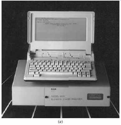
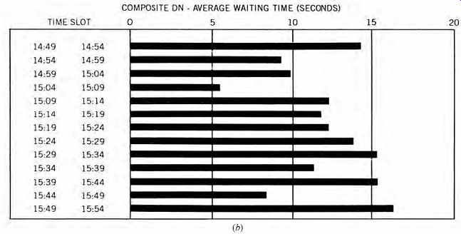
FIG. 17 Building elevator traffic studies can be performed quickly and accurately
using a traffic analyzer with multiple inputs to feed data via appropriate
software into a laptop computer (a). The unit illustrated has 64 inputs, which
are scanned once per second, and is capable of unattended monitoring for a
week.
The accumulated data on call registration, response time, waiting time, maximum interval, cars in service, and so on, can be viewed visually on the computer screen or printed out as in (b). (Courtesy of UNITEC Parts Co.)
25. REHABILITATION WORK: PERFORMANCE PREDICTION
The primary reason for rehabilitating an existing elevator system is to improve its operating performance. Traction machinery has extremely long life, particularly in the gearless configuration.
Thus, the usual rehabilitation project consists of replacing the m-g set, car control panel, and group controller with solid-state, microprocessor-con trolled programmable equipment, while retaining the original traction equipment. The car door operator, which controls door action, is usually also replaced because door opening and closing characteristics are an important factor in overall trip time and therefore in system performance.
Major manufacturers have developed computer-based elevator system simulators. Such programs enable architects and owners to input design (or as-is) building data, and to receive graphic and text output on the performance of pro posed systems. Because such programs are interactive, the user can change the input data and the characteristics of the proposed equipment until the desired performance level is reached. These programs are particularly useful in modernization work because the owner sees in advance the operation of a proposed system in his/her building and can make appropriate decisions based upon good information.
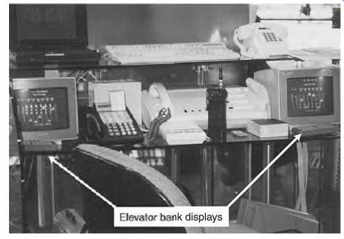
FIG. 18 Dedicated elevator display computer terminals are part of the extensive
control and communication equipment installed at a lobby control desk in a
New York City skyscraper. (Photo by B. Stein.)
26. LOBBY ELEVATOR PANEL
The traditional lobby elevator control and information panel for each elevator bank, which was usually wall-mounted adjacent to the related elevators, has become one or more computer monitor screens positioned at a lobby desk ( FIG. 18) and/or in the building maintenance office. In addition, an information-only screen is frequently wall mounted adjacent to the related elevators for the edification of waiting passengers.
The information displayed on the screen includes car locations, movement direction, waiting corridor calls, and any special status data. The control functions available at the computer terminal permit intervention to establish special types of operation including:
• Car movement without operating the usual audible and visual signals (inconspicuous riser)
• One or more cars removed from supervisory control and operated manually (attendant or independent service)
• Cars selected for night or weekend service while the other cars are shut down
• Car(s) assigned to a particular floor on a fixed- or priority-basis call (convention feature or priority) Among other control functions are those concerned with emergency service, including the "fireman's return" feature required by ANSI and many local fire codes (Sections 46) and the controls related to switching of power between cars in the event that operation on emergency generator power is necessary.
In addition, means of two-way communication with each car and other selected locations are provided at the control center.
27. CAR OPERATING PANEL
A typical car operating panel is illustrated in FIG. 19. Every car panel (station) is equipped with full-access buttons for call registry, door-open, alarm, emergency stop, and firefighter control. Also always provided is an intercom device that permits communication with the building control office. A door-close button is sometimes provided if extensive hand operation of the car is anticipated. It is activated only when the car is under manual control. Controls that do not concern the normal passenger are grouped in a locked compartment in the car panel.
These include a hand-operation switch; light, fan, and power switches; and any special controls such as security and emergency devices. Finally, a compartment accessible only to technicians contains the devices controlling door motion, car signals, door and car position transducers, load-weighing control, door and platform detection beam equipment, speech synthesizer (if used), and visual displays.
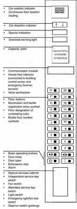
FIG. 19 Typical car operating panel. Designs of these panels vary widely,
but the essential components are as shown.
cont to part 2 >>
Prev. | Next
Home Similar
articles top
of page