AMAZON multi-meters discounts AMAZON oscilloscope discounts
cont. from part 2
PHYSICAL PROPERTIES AND SPATIAL REQUIREMENTS OF ELEVATORS
39. SHAFTS AND LOBBIES
Elevator lobbies and shafts are one of the major space issues with which the architect is concerned.
The elevator lobby on each floor is the focal point from which corridors radiate for access to all rooms, stairways, service rooms, and so forth. Such lobbies must be located above each other. The ground-floor elevator lobby (also called the lower terminal) must be conveniently located with respect to the main building entrances. Equipment within or adjacent to this area should include public telephones (if pro vided), a building directory, elevator indicators, and possibly a control desk (see FIG. 18).
Lobbies should provide adequate area for the peak-load gathering of passengers to ensure rapid and comfortable service to all. The number of people contributing to the period of peak load (15- to 20-minute peak) determines the required lobby area on the floor.
Not less than 5 ft 2 (0.5 m2) of floor space per person should be provided at peak periods for waiting passengers at a given elevator or bank of elevators. The hallways leading to such lobbies should also provide at least 5 ft 2 (0.5 m2) per person, approaching the lobby. Under self-adjusting relaxed conditions, density is about 7 ft 2 (0.65 m2) per person. During peak periods crowding occurs, however, reducing this to 3 to 4 ft 2 (0.3-0.4 m2) per person. An acceptable compromise is 5 ft^2 (0.5 m^2) per person.
The main lower terminal of elevator banks is generally on the street-floor level, although it may be on a mezzanine level when the elevations of the street entrances vary so that one side of the building is at mezzanine level, whereas another entrance is lower. Such a situation is ideal for the use of escalators, which can economically and rapidly carry large numbers of people between levels, thus making practical and efficient a single main lower elevator terminal. The upper terminal is usually the top floor of the building. Typical dimensional data and lobby arrangements are shown in Figs. 26 to 28.
40. DIMENSIONS AND WEIGHTS
Most manufacturers and elevator consultants will, upon request, supply standard layouts for elevators-including dimensions, weights, and structural loads. Furthermore, to assist in preliminary design, major manufacturers have agreed upon and publish a set of Standard Elevator Layouts via their trade organization, the National Elevator Industry, Inc. (NEII). One such standard is reproduced in FIG. 29 for 500- to 700-fpm (2.5 to 3.6-m/s) gear less units in the full range of car capacities. These standards are available from the NEII.
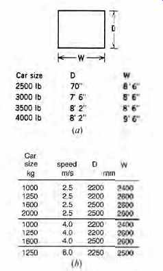
FIG. 26 Rough hoistway dimensional data for use in schematic design. (a)
I-P elevator sizes and dimensions. (b) SI elevator sizes and dimensions.

FIG. 27 Lobby groupings for single-zone systems: (a) three-, (b) four-, (c)
six-, and (d) eight-car groups.
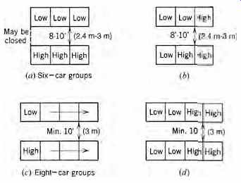
FIG. 28 Lobby groupings for multiple zone systems. Arrangement (a) is preferable
to (b), and (c) to (d). Groups with more than four cars in a row are not used
because end-to-end walking time would excessively lengthen landing stops and
hence total travel time.
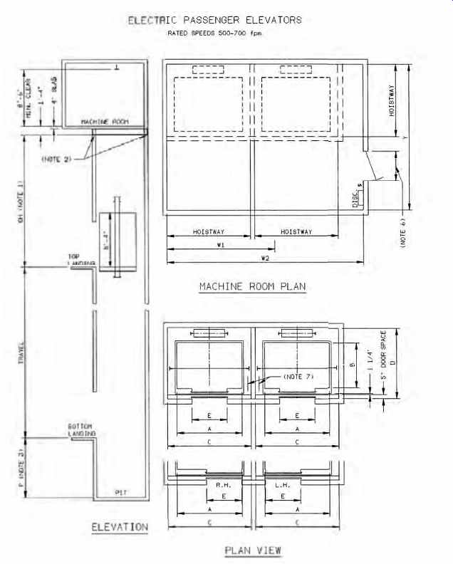
FIG. 29 Typical elevator installation dimensional data. (Reproduced from
Vertical Transportation Standards, 7th ed., © 1992, with permission of National
Elevator Industry, Inc., 185 Bridge Plaza North, Fort Lee, NJ 07024.)

FIG. 30 Manufacturer's layout data for a bank of six 3500-lb (1588-kg), 700-fpm
(3.45-m/s) gearless passenger elevators. Equipment shown in the machine room
is the thyristor control for dc traction machines. Because each controller
provides group supervisory control in this design (Otis Elevonic 411), no separate
group supervisory equipment is shown. No additional space would be required
if a UMV drive with m-g sets were selected rather than thyristor control. (Courtesy
of Otis Elevator Co.)

FIG. 31 Typical data for a basement traction machine (underslung) arrangement,
used where a penthouse is unavailable or undesirable. (Courtesy of Montgomery-KONE.)
As may be seen from FIG. 29, in providing for an elevator installation it is necessary to consider such factors as the depth of the pit, the dimensions of the hoistway, the clearance from the top of the hoistway to the floor of the penthouse, the size of the penthouse, and the loads that must be carried by the supporting beams.
The penthouse floor (and the secondary-level floor where required) are located above the shaft of each elevator and need approximately 1½ stories of additional height above the top of the support beam of a given elevator when it is standing at its top-floor location. The actual floor area required by the elevator traction machine and its controls is roughly two times the area of the elevator shaft itself.
The machine room contains the bulk of the elevator machinery. Because some of this equipment must be moved for maintenance, it is advisable to furnish an overhead trolley beam that can be used during installation as well. The maximum beam load is supplied by the elevator manufacturer.
Some typical machine room dimensional data are listed in TABLE 12, taken from actual installations. Because of multiple drive options and flexibility in equipment arrangements, no general conclusions can be drawn from these figures; they are listed simply to give a general picture of requirements. A manufacturer's layout giving dimensional data for the hoistway and machine room is shown in FIG. 30.
TABLE 12 Typical Elevator Machine Room Dimensions
When penthouse space is not available and a hydraulic unit is not desired, a basement traction unit, also referred to as an underslung arrangement, can be used. These units are always low-speed (100 to 350 fpm [0.5 to 1.8 m/s]) and are therefore applicable only where rise is limited and traffic is light to medium. Figure 31.31 shows a typical shaft section for this design with car and dimensional data.
41. STRUCTURAL STRESSES
For structural design, it is necessary to know the overhead load that must be supported by the foundations, by structural columns extending up to the penthouse, and by the main beams that sup port the penthouse floor and subfloor. These loads (reactions) are supplied by manufacturers and usually include the actual dead weights of equipment when the elevator is not in motion, plus the added weight caused by the momentum of all moving parts and passengers when the elevator is at top speed and is suddenly stopped rapidly by the safety devices.
FIG. 32 Elevator traction motor power requirements per car. An m-g set drive (if used) is approximately 20% larger than a traction machine.
POWER AND ENERGY
42. POWER REQUIREMENTS
The power required by an elevator drive is that which is needed to provide the necessary traction and to overcome friction. Because power is equal to the rate at which work is done, elevator motor size is directly proportional to the speed of the system. In other words, it requires proportionately more power to lift a 3000-lb (1361-kg) car at 700 fpm (3.6 m/s) than at 200 fpm (1.0 m/s). This relationship is shown in FIG. 32, which shows the minimum size of a dc elevator traction motor as a function of speed for cars of different capacity. (For power data on hydraulic elevators, see Sections 9.) As friction is higher in a geared machine than in a gearless unit, the geared machine traction motor must be larger for the same car speed. The size of the traction machine shown in FIG. 32 is independent of the power supply design (m-g set, VVVF, thyristor control) because it is determined purely by traction system requirements. (In practice, however, traction motors with VVVF control are frequently smaller because they operate more efficiently.) An elevator moves only about 50% of the time, the remainder being spent standing at various landings. As the number of cars in a bank increases, the probability of all the cars being in operation simultaneously decreases, resulting in a system demand factor of less than 1.0. The factor for different group sizes is shown in FIG. 32.
As an example of the use of the power curves, consider a bank of five 3500-lb (1588-kg), 600-fpm (3.0-m/s) units. From FIG. 32, each car requires 48 hp (36 kW):
group demand factor = 0.67 total instantaneous power required
= 5 × 48 × 0.67 = 160 hp
(= 5 × 36 × 0.67 = 120 kW)
Note that this is the traction motor power r requirements. If an m-g set with an overall efficiency of 80% is used to drive the traction motor, the elevator system power requirement is system power 160 hp 80%eff 200 hp ==(120 kW/0.80 = 150 kW) which must be provided by the building electrical system. If a solid-state power supply system with a (typical) efficiency of 92% is used, the system power requirement will be only system power 160 hp 92%eff 174 hp == (120 kW/.0.92 = 130 kW) which is a 13% reduction from the previously calculated 200-hp (150-kW) requirement.
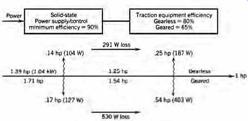
FIG. 33 Block diagram showing losses in the system per horsepower (kW) delivered
to the elevator car and the equivalent watt ages. Note that the losses in a
geared system are almost double those of a gearless one. Figures shown are
for solid-state thyristor controls.
43. ENERGY REQUIREMENTS
The energy used by an elevator is essentially the system friction, including the heat generated by the brakes plus the electrical losses in the traction motor and power supply equipment (rotary or solid state). The energy expended in raising a car and its passengers is simply stored as potential energy. It is returned to the power system when the car and passengers descend via the system of regenerative braking used in almost all elevator systems. Refer to FIG. 33, which shows the approximate efficiencies of the components of a typical system. With these data, it is possible to calculate a system's energy consumption.
EXAMPLE 2 Given a system of five 3500-lb (1588-kg), 600-fpm (3.0-m/s) gearless cars, calculate:
(a) The heat generated in the machine room during peak periods; assume solid-state control (b) The approximate monthly energy cost; using a combined demand/energy rate of $0.08/kWh
SOLUTION
(a) During peak periods, the traction motor operates approximately 50% of the time and is at standstill the other half. Assume that, while operating, it draws 90% of the full load (with a VVVF power supply this figure is reduced considerably). Therefore, for one car, from FIG. 32, traction motor = 48 hp (36 kW) Total loss per machine:
In controls:
48 hp
0.9 eff 90%load 50%operation 10%loss ×× 90%load ×
= 2.4 hp (1.8 kW) In traction motor:
48 hp × 90% load × 50% operation × 20% loss
= 4.32 hp (3.2 kW) total = 6.72 hp = 17,100 Btu/h (equivalent to 5 kW)
Because five elevators are operating, the total heat generated is
5 × 17,100 Btu/h = 85,500 Btu/h (equivalent to 25 kW)
This is roughly the heating capacity of a home furnace. As a result, machine room temperatures in warm climates frequently reach 120ºF (49ºC). (No diversity is taken because all the machines are operating and the heating is additive; diversity is applicable only in calculating instantaneous load.) As solid-state elevator equipment is much less tolerant of high ambient temperatures than the electromechanical switches and relays previously used, an elevator machine room should be held to a maximum dry-bulb temperature of 90ºF (32ºC). (Temperatures above 90ºF (32ºC) can result in unreliable elevator system performance.) This limit can sometimes be accomplished by thermostatically controlled forced ventilation, particularly if spill over air from an air-conditioned space is available.
However, because machine rooms are frequently on the building roof and exposed on all surfaces to ambient temperatures and solar radiation, air conditioning may be necessary. It is also important to prevent machine room temperature from dropping below 55ºF (13ºC). This can usually be done with one or more unit heaters, which will normally operate only during the winter, and then only on nights and weekends.
In actual design situations, accurate heat loss values, which are available from manufacturers, would be used, along with accurate heat gain and heat loss calculations for the specific machine room being designed. Frequently, use of thermal insulation, thermostatically controlled louvers, and sunshading can ease the thermal load and result in appreciable savings in money and energy. Because of the high initial and operating costs of air conditioning, some elevator manufacturers use control components that are tolerant of high temperatures. This point should be carefully examined with proposed elevator equipment manufacturers and the conclusions reflected in the elevator system specifications.
(b) To calculate a monthly energy cost, an estimate must be made of the total usage of the system.
Assuming the system to be in an office building, a reasonable breakdown of operation during a 24-hour day would be:
2 hours at peak use
2 hours at 70% of peak
6 hours at 50% of peak
14 hours at 10% of peak
This gives a weighted average of 30% of peak load for the elevator bank. Therefore, per car energy = 30% × total losses × 24 hours
= 0.3 × 6.72 hp (or 5 kW) × 24 hours
= 48 hp-h (or 36 kW-h) = 36 kWh/day/car Monthly cost would be 36 kWh day 25 days $0.08 ×× 25 days
= $72/month/car
= $360/month for the bank
This figure would be lower with a VVVF power supply and higher for a Ward-Leonard (m-g set) arrangement.
44. ENERGY CONSERVATION
A reduction in energy consumption can be accomplished by implementing the following recommendations:
For Existing Elevators
1. Increase the interval during nonpeak hours.
2. Replace m-g sets with a solid-state dc power supply or ac traction motors with a VVVF power supply. This conserves energy not only due to the higher efficiency of the power sup ply, but also because energy consumption of idling machines is eliminated.
3. Reclaim machine room waste heat.
4. Shut down some units completely during off hours.
For a Building in the Planning Stage
1. Base the design on the maximum recommended trip time.
2. Use the lowest speeds possible within a type--that is, geared or gearless.
3. Use gearless equipment whenever possible.
4. After construction, implement the energy conservation recommendations for existing elevators.
Because elevator shafts can induce a powerful stack effect, measures should be taken to counteract this potential loss of heat during the heating season.
45. EMERGENCY POWER
Major power failures and local brownouts have demonstrated forcefully the need for a standby or emergency power source of adequate size to operate an affected building's elevators. Few experiences are so harrowing as being trapped in the crowded confines of a small box suspended in a long vertical shaft, with little or no light, and complete strangers for companions.
A common misconception about elevators is that on failure of power, the cars will automatically descend to the nearest landing, where an exit is then possible. In reality, the car brake is set immediately upon power outage and the car remains stationary. Hydraulic cars can be lowered by operation of a manual valve; small traction cars can be cranked to a landing by hand, but large cars are fixed in position. This is particularly bad for cars in blind shafts-that is, express shafts with no shaftway doors. In such cases, escape from the cars via a hatchway is not practical; when emergency power is not available, the undesirable option of breaking through the shaftway walls is the only recourse.
In addition to simple inconvenience, loss of elevator service in facilities such as hospitals and mental and penal institutions constitutes a danger to life. For this reason, most codes require that emergency power be available in specific building types to operate at least one elevator at a time, and for elevator lighting and communications. Many installations separate the emergency power functions, providing a generator for elevator traction power and separate individual elevator battery packs for communications, lighting, and, prefer ably, the car fan. The last two items can be furnished as an option by elevator manufacturers with their cars.
The generator is normally sized to supply one elevator motor at a time, with manual or automatic switching arranged between unit controllers. Thus, each car in turn can be brought to a landing and thereafter a single car retained in service. If it is desired to operate more than one car, a larger generator can be installed. This might well be the case in a multi-wing building with critical service requirements, such as a hospital.
The amount of power required, the size of the emergency generator, and the equipment size necessary to absorb regenerative power are all data that can be furnished by a consulting engineer and the elevator manufacturer.
SPECIAL CONSIDERATIONS
46. FIRE SAFETY
Most fire codes specify the procedures that elevator control equipment must implement once a fire emergency has been initiated. Details vary some what, but in general the actions are these:
1. All cars close their doors and return nonstop to the lobby or another designated floor, where they park with the doors open. Thereafter, they are operable in manual mode only, by use of the firefighter's key in the car panel.
2. All car and hall calls are canceled, and call registered lights and directional arrows deactivated.
3. The fire emergency light or message panel in each car is activated to inform passengers of the nature of the alert and that cars are returning to a designated terminal.
4. Door sensors and in-car emergency stop switches are deactivated.
5. Traveling cars stop at the next landing without opening their doors and then proceed to the designated terminal.
The cars can then be used by trained personnel to transport firefighters and equipment and for evacuation. In the event of a false alarm, the emergency procedure can be overridden at the (lobby) control point and the system returned to normal while the source of the alarm is located.
(This is a particularly important feature in large buildings with automatic fire alarm systems containing hundreds of fire, smoke, and water-flow detectors.)
47. ELEVATOR SECURITY
Elevator security has two key aspects: physical security of riders and consideration of the elevator as a portal in a building-access security system.
(a) Rider Security
This problem is particularly difficult inasmuch as a traveling elevator is an enclosed space that can be rendered inaccessible simply by pressing the emergency stop button. Thereafter, an attacker can escape at a floor of his/her choice.
To reduce this danger (to some extent), elevators are equipped with alarm buttons that alert residents and security personnel (if any). Every elevator, by code, must be equipped with communication equipment. A two-way communication system with "no-hands" operation in the car is particularly effective for security. When a closed-circuit TV monitor is added, utilizing a wide-angle camera in each car ( FIG. 34), the security problem will have been addressed to a considerable extent. Using a communication and TV system presupposes continuous monitoring of the building security desk so that an incident will be detected.
(b) Access Control
This is often a matter of restricting access to (and from) a floor or car. This can be accomplished by pushbutton combination locks or coded cards, the proper use of which will permit access (see Section 30). However, if a second (unauthorized) person accompanies an authorized person, the effectiveness of this type of access control is seriously compromised. In sum, the most effective security system is a combination of automatic monitoring and access devices coupled with continuous supervision by persons who know the appropriate actions to take in an emergency.
48. ELEVATOR NOISE
Elevator operation, with its rotating, sliding, and vibrating masses, can be a cause of serious noise disturbance to quiet areas such as sleeping rooms, libraries, and certain types of office space. Noise and vibration can be reduced by the appropriate application of noise control strategies and vibration isolators (e.g., between guide rails and the structure), but primarily by placing noise sensitive areas away from shafts and machine rooms. The clatter and whirring sound associated with older machine rooms (and caused by relays, step switches, m-g sets, and sliding contacts) can be entirely eliminated by the use of solid-state equipment.
FIG. 34 Wide-angle TV camera intended for elevator car surveillance. A prominent printed warning in the car is an integral part of the system's effectiveness. (Photo courtesy of Visual Methods, Inc.)
49. ELEVATOR SPECIFICATIONS
Two basic types of specifications for elevator equipment, as for other types of equipment, are utilized.
These are the prescriptive (equipment-based) and performance (outcome-based) approaches. Performance specifications describe job conditions and invite contractors to submit detailed proposals that will meet explicit design criteria. The bur den of comparing proposals then falls upon the owner, who-if competent to properly perform such an evaluation-would probably do better to utilize an equipment-type specification in the first place.
In recent years, the use of performance specifications has increased because of the advent of pre-engineered, premanufactured systems. These are supplied by the major elevator manufacturers and have the following advantages:
1. Approximately 10% lower cost than a custom designed system
2. A completely engineered and tested system whose performance and cost are known exactly
3. Rapid delivery
4. Minimum supervision required by the owner and architect
If architects decide to use a custom-designed system, they must prepare detailed drawings and specifications. The specifications must include:
• Elevator type, rated load, and speed
• Maximum travel
• Number of landings and openings
• Type of control and supervisory system
• Details of car and shaft doors
• Signal equipment
• Characteristics of the power supply
• Finishes
The last item can be left as a dollar allowance for architectural treatment of the car interior.
Because the selection of, and technical specifications for, elevators are specialized and complex, the services of an elevator consultant are usually required.
In addition to the technical portions of the specifications, it is imperative that the following items be covered in detail.
(a) Owner's Responsibility
The general construction contractor (acting for the owner) normally provides the following:
1. The hoistway, including a properly designed, lighted, drained, waterproofed, and ventilated machine room and pit
2. Access doors, ladders, and required guards
3. Guide rail bracket supports, and support for machine and sheave beams
4. Electric feeder terminating in a switch in the machine room
5. Hoistway outlets for lighting, power, and telephone
6. Temporary lighting and power during construction
7. Concrete machine foundations
8. Vents, holes, and other work to satisfy fire codes
9. All cutting, patching, and fabricating of walls, beams, masonry, and so on
10. Coordination of all work 11. Any special work, as negotiated and specified
(b) Elevator Contractor's Responsibility
Provide a complete, working, tested, and approved system in accordance with specifications, plus any special work such as painting, special tests, work scheduling, and temporary elevator service. The system is "inserted" into the building framework described in Sections 49(a).
(c) Special Job Conditions
These include work restrictions, scheduling, penal ties or bonuses, test reports, and the like.
In alteration and modernization work, the problems of coordination are complex, and an elevator contractor experienced in this type of work should be selected. To this end, in all elevator con tract work, bids should be solicited from parties named on qualified bidder lists. A complete elevator contract includes a warranty and provisions for maintenance of the installation for a specific period after completion.
FIG. 35 Disc-shaped hoisting motor rigidly mounted on the elevator guide rail. The ac synchronous motor is connected directly to the hoisting cable drive sheave with no intervening gears. Brakes and controls are built into the assembly. (Courtesy of Montgomery-KONE.)
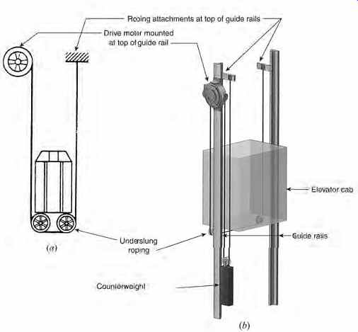
FIG. 36 Schematic (a) and pictorial (b) representations of the disc-motor-driven
elevator arrangement. (Part b Courtesy of Montgomery-KONE.)
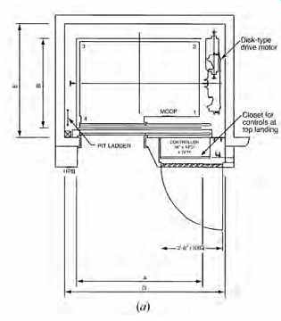
FIG. 37 (a) Section through the top of a hoistway showing dimensional data
for a single 2500-lb (1134-kg), 200-fpm (1 m/s) installation with a rise of
up to 80 ft (24 m). Note that the drive motor occupies less than 2 ft (0.6
m) in the width of the hoistway and that the elevator motion and operating
controls (Sections 4) are installed in a closet 42 in. (1.07 m) wide and approximately
20 in. (508 mm) deep at the top landing. (b) Elevator system basic data for
the simplex (single) unit shown in (a). (Courtesy of Montgomery-KONE.)
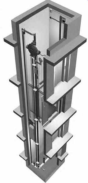
FIG. 38 Pictorial representation of a disc-type traction motor hoistway showing
the system's essentials. (Courtesy of Montgomery-KONE.)
50. INNOVATIVE EQUIPMENT
The elevator industry is constantly developing new equipment to improve the operation and safety of standard systems. In addition, novel designs that are essentially different from standard traction arrangements are always being developed in an attempt to increase the efficiency of space use and to decrease the high cost of standard traction machinery. Among the interesting designs being developed in the first category is one that permits a car to travel horizontally in addition to its normal vertical motion, the purpose of which is to increase the number of cars using a single shaft. The second category includes a design using a linear motor (as opposed to a rotating unit) to supply traction power. These and several other special designs are discussed in Section 32.
A recently developed interesting variation of the conventional traction design that effects a considerable space reduction is shown in Figs. 35 to 38. At this writing, its principal applications are in low-speed, low-rise installations now generally serviced by hydraulic elevators, but with higher speeds and rises under development. The novelty of the design lies in the use of a flat (disc shaped), synchronous ac gearless hoisting motor, which, due to its flat disc shape, can be mounted directly on the main car guide rail at one side of the shaft (see FIG. 35). This essentially removes the need for a penthouse and a large machine room above the hoistway. Due to the traction motor's position at the side of the hoistway, the car is roped in an underslung arrangement, as shown in FIG. 36. Additional space economy is achieved by the use of a small drive controller built into an alcove at the top landing (see FIG. 37). The pictorial hoistway representation in FIG. 38 shows the equipment arrangement, demonstrating the absence of a penthouse and the limited machine room space requirement. An additional advantage of this arrangement is that the elevator loads and reactions are borne by the (stiffened) guide rail and transferred directly to the concrete pit below the bottom landing. This reduces the reactions borne by the machine room level in a conventional traction design and results in reduced structural loads.
Compared to hydraulic elevators, this design exhibits considerable energy economy due to its use of a gearless traction machine.
References and Resources
Stein, B., J. Reynolds, and W. McGuinness. 1986.
Mechanical and Electrical Equipment for Buildings, 7th ed. John Wiley & Sons. New York.
Strakosch, G. R. 1983. Vertical Transportation, Elevators and Escalators, 2nd ed. John Wiley & Sons. New York.
Prev. | Next
Home Similar
articles top
of page