| PREV.: Direct-Acting Reliefs | NEXT: Operating Principles of Various Main Poppet Designs | Article Index | Home |
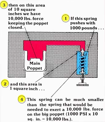
AMAZON multi-meters discounts AMAZON oscilloscope discounts The pilot operated relief performs the same function as the direct operated design in that it serves to protect the system components from over pressure, and it limits the maximum output force. This model, however, offers advantages in both versatility and performance which make it more desirable than direct operated valves. As already discussed, direct operated valves are limited in their capability to handle large flows at high pressures. Although some designs are more capable than others, the pilot operated design is really the only way to relieve flows of more than 75 GPM. The major disadvantage is that large valves have larger poppet areas exposed to system pressure. This larger area multiplied by high pressure creates a need for an undesirably large spring. For this reason, pilot operated valves use the principle of the “hydraulic level” to multiply the force of a smaller spring. |
(See Color code legend for above image)
BASIC PILOT OPERATED CONSTRUCTION
The pilot-operated relief is nothing more than two separate, direct-operated combined into one unit. One section is a relief designed to handle high flow at low pressure while the pilot relief handles high pressure at very low flows. Let us consider the low-pressure high-flow portion.
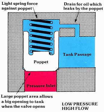
The main valve consists of a housing with a pressure inlet and a tank outlet. Like a simple direct operated relief, pressure is blocked from tank by the main poppet or spool. The poppet is held against its seat (or the spool is held in the closed position) by a light spring force. Since this portion of the relief must handle large flows, the main poppet has a relatively large poppet area exposed to the system pressure. The combination of a large area being supported by a light spring makes the valve capable of handling large flows at low pressures. Since this portion uses a weak spring, it has a low spring constant which does not result in a high pressure override.
Above:
Low Pressure High Flow (See Color code legend for
above image)
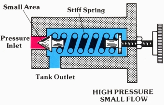
The pilot valve is also a simple direct operated relief. However, this valve incorporates a stiff spring used in conjunction with a small area exposed to system pressure. This makes the pilot valve capable of handling high pressures but very little flow. Should this section have to handle large flows, the stiff spring constant and small seat area would result in objectionable pressure override.
Above:
HIGH PRESSURE SMALL FLOW. (See Color code legend for
above image)
By using these two components to accomplish a single function, we obtain the ability to handle large flows at high pressures. Let us now take a closer look at the static and dynamic interaction of the two sub-assemblies.
THE STATIC OR CLOSED CONDITION
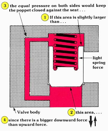
Pilot operated reliefs stay closed because of the principle of Pascal’s Law. In reference to the figure, the fluid above and below the main poppet is captive in a closed container. Since the area on top of the main poppet is somewhat larger than that on the bottom, there is a larger closing force than opening force, and the valve remains closed. A light spring force is incorporated above the poppet which not only keeps the valve closed during start-up, but also provides an additional unbalancing force when pressures are equal above and below the poppet. Under these conditions, you can see that the valve is closed no matter whether there is 100 PSI or 10,000 PSI in the system.
(See Color code legend for above image)
THE DYNAMIC OPENING OF THE RELIEF
By adding the high pressure low flow relief to the chamber above the main poppet, we can limit the pressure and thus the closing force. The pressure in the oil above the main poppet is regulated as follows:
In reference to the diagram, system pressure is exposed to areas Al, A2 and A3. As pressure increases, it increases equally on all areas. As long as area A3 remains closed, there is no flow, and the pilot circuit conforms with the principles of Pascal’s Law. Under these conditions, we have a larger closing force than opening force; thus, the valve remains closed. Nevertheless, when pressure over area A3 exceeds the spring force, oil escapes from the previously closed container, which establishes a flow in the pilot circuit.
It is this flow which allows the valve to open.
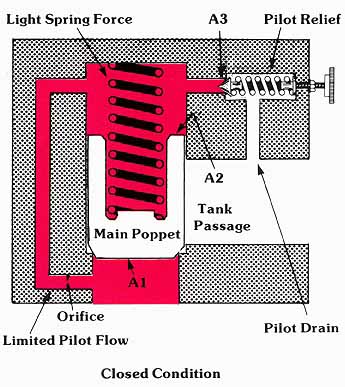
Above: Closed Condition (See Color code legend for above image)
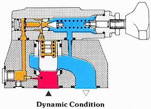
Above: Dynamic Condition (See
Color code legend for above image)
When pressure is sufficient to overcome the spring of the high pressure pilot relief, we immediately see a decay in pressure above the main poppet. This establishes a pressure imbalance across the orifice in the pilot circuit which necessitates a flow of oil across that orifice. This flow of oil tries to replenish the oil lost over the piloting relief. However, in trying to reestablish a static condition, this flow causes a pressure differential which is sufficient to open the main pop pet. This, in effect, relieves oil to tank at the pressure setting of the piloting relief. If, on the other hand, system pressure decays, the pilot relief will close. Equal pressure is re established on both sides of the main poppet due to the principles of Pascal’s Law. When pressures above and below the main poppet are equal, the main poppet closes because of the larger downward force. Remember, some of the closing force is created by the light spring above the main poppet.
REMOTE PILOTING
Another reason the pilot operated relief valve is often required is that with it, the pressure can be adjusted at the operator’s station, while the main valve can be located elsewhere in the system. This feature is referred to as remote piloting. (see image below)
Since the force on the main poppet is controlled by pressure in the pilot circuit, it is possible to connect other small piloting relief valves in this piloting circuit. The maximum pressure of the main system is governed by the pilot relief with the lowest pressure setting. (see image below)
If the main pilot relief is set for the highest possible system pressure, then the small direct operated relief, which can be mounted remotely in the operator’s control console, can be used to adjust system pressure to anything lower than that set on the main valve. (see image below)
MULTIPLE PRESSURE SELECTION
Multiple pressure settings can be set on any number of small piloting relief valves. By using isolating directional control valves, individual pressures can be selected via electrical signals. This offers the ability to quickly recall set pressures by selecting the relief valve with the proper preset pressure. When the solenoid valve is in its closed position, its respective relief valve is blocked from the main relief valve’s pilot circuit, and does not effect main system pressure. Under this condition, the small pipe from the main relief to the isolating directional control is only an extension of the “Pascal” closed container. (see image below)
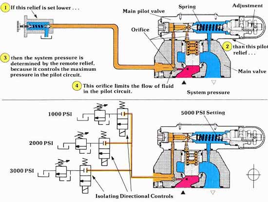
Above: Fig 1: Remote piloting. Fig 2. Multi Pressure selection. (See Color code legend for above image)
VENTING THE PILOT-OPERATED RELIEF
One of the most important features a pilot-operated relief provides is a capability to vent the main system. The terminology “venting main system” means allowing all pump out put to flow pressureless to the tank. This is quite important because it takes very little horsepower to circulate oil at little or no pressure. If the hydraulic system is not being required to do work, then by venting the system, the full hydraulic horsepower capability of the pump is not turned into heat and wasted, as it would be if the pump had to push the oil over the relief at full system pressure. It allows the hydraulic system to idle. The venting feature is such an important feature to industrial hydraulic systems that most manufacturers offer this feature as a standard option in the pilot operated relief line of components. By mounting a small directional control directly on top of the pilot valve of the main relief, the pilot circuit can either be blocked from or connected to the internal tank chamber.
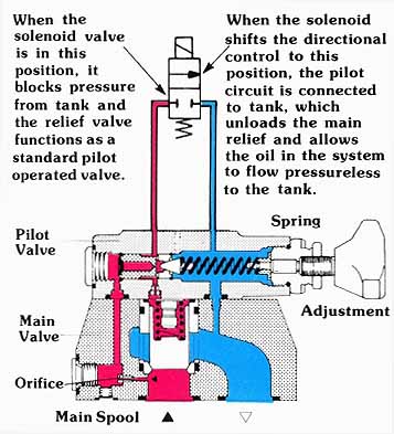
Above: Venting the Pilot-operated Relief. (See
Color code legend for above image)
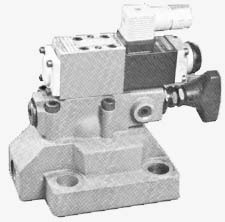
Above: The actual valve shown in preceding schematic: a Rexroth
Pilot-operated Relief.
This type of valve is commonly referred to as a solenoid vented relief. More often than not, the directional control is shifted from the blocked to the open position, or vice versa, by means of a solenoid. For purposes of this section, a solenoid is defined as a component which takes an electric current (the same that is used to light an ordinary household light bulb), and transforms that electrical energy into a linear force. This force is then used to change the position of (shifts) the directional control. In talking about solenoid vented relief valves, two terms are often encountered:
Normally open solenoid vented reliefs are those which allow the oil to flow pressureless to tank when no electricity is being supplied to the solenoid (de-energized). Energizing the solenoid loads the system by reestablishing the pilot circuit to that of a standard pilot operated relief.
Normally closed valves, on the other hand, function in just the opposite manner. When de-energized, the relief functions as a standard pilot operated relief. The system is vented by energizing the solenoid.
In hydraulic circuits, it is more common to find normally open valves than it is to find those which are normally closed. The logic behind this is that a normally open valve is fail-safe in the event of a power failure in the control circuit. If something goes wrong in the control circuit of a normally closed valve, system pressure is at its highest rather than being vented as it would be with a normally opened valve.
HIGH VENT OPTION
We said earlier that the main section of the pilot operated relief is nothing more than a low pressure, high flow, direct operated relief. When the pilot circuit is vented, the pump is actually vented to tank at a pressure determined by this low pressure relief.
To obtain maximum efficiency in the vented condition, the light spring force on the main poppet is usually designed to relieve the pump flow to tank at a pressure of less than 50 PSI. Nevertheless, it is sometimes necessary for proper system operation to maintain a residual pressure of higher than 50 PSI. If this is the case, a higher vent pressure can be achieved by selecting the high vent option.
The high vent option is nothing more than a stronger spring holding the main poppet or spool in the closed position. With the high vent spring, approximately 75 PSI is required to open the main poppet. The high vent option is particularly helpful in systems in which we must maintain pilot pressure for pilot operated directional controls, or in situations in which it is necessary to push oil through heat exchangers or filters while the system is idling.
EXTERNAL PILOT DRAIN
In standard pilot operated relief valves, the spring chamber of the pilot valve is drained to the valve’s tank port through internal passages. A problem may arise in some applications when the pressure in the tank port varies during different parts of the cycle. This happens when resistances down stream of the “T” port are subjected to different flow rates as the relief valve relieves more or less flow. Remember, it takes more pressure to push a large flow of oil back to tank through filters and heat exchangers than it does when there is little flow. With internally drained valves, tank pressure is exposed on the back side of the pilot poppet, and adds a force of pressure multiplied by area, to the force of the spring. If tank pressure varies, so does the pressure in the main system, since there is a varying force holding the pilot poppet against the seat.
If fluctuation sin the main system pressure cannot be tolerated, the spring chamber of the pilot can be isolated and drained through a separate port. This is known as an external drain option.
In valves in which the drain port has been designed to withstand full system pressure, a second use of the drain port is often desirable. We can make use of the fact that back pressure in the spring chamber adds to valve setting and use this as the remote pressure adjustment. As will be shown in our discussion of reducing valves, this has a particular advantage when it is necessary to adjust two pilot operated valves from the same adjustment while maintaining a fixed differential between these pressure settings.
As shown in the cross-sectional illustration, the lowest pressure is set on the main valve when we remotely adjust by using the “Y” port, as opposed to the highest pressure setting on the main valve when using the “X” port. Precaution must be taken in using the “Y” port because there is no inherent safeguard preventing the operator from exceeding the maximum pressure rating of the valve. If, for example, both the pilot valve and the remote adjustment were to have spring settings of 3000 PSI, then the main relief would relieve at 6000 PSI, which is in excess of its pressure rating. Nevertheless, if this method of adjustment offers advantages to the system design, then adequate safeguards can be provided by proper component selection. Being aware of the possibility of overpressure, the designer can select a lockable pressure adjustment on the main pilot valve. In this manner, the resistance of the pilot valve’s spring can be locked at its absolute minimum value (100 PSI). Then, by selecting a remote relief with the proper spring, you can be assured that the operator cannot exceed the maximum pressure rating.
USING THE “Y” PORT FOR LOAD SENSING
Although a complete discussion of speed control and energy loss will be covered in a later section, it is relatively simple for us to design a circuit which makes the pressure setting of a pilot operated relief sensitive to changes in load induced pressure. The major advantage here is that the pressure of the relief valve self regulates when circuits are operating over a broad load range. Because the load pressure can be sensed, the pump flow can always be relieved to tank at a pressure slightly higher than that induced by the load. This not only saves energy, but it gives a constant pressure drop across the fixed resistances to flow in the system, resulting in constant actuator speed. To further explain this concept, let us consider a typical circuit with and without the load sensing feature:
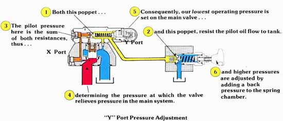
Above: “Y” Port Pressure Adjustment. (See Color
code legend for above
image)
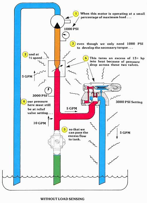
Above: WITHOUT LOAD SENSING. (See Color
code legend for above image)
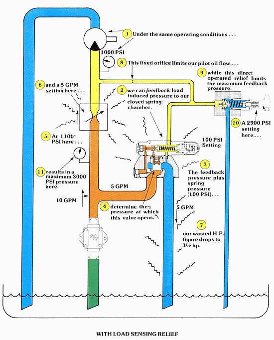
Above: WITH LOAD SENSING RELIEF. (See
Color code legend for
above image)
The example only introduces the possibility of energy saving by load sensing with the relief. With a little imagination, this concept could result in considerable energy savings in a multitude of applications. Our only warning is that the size of the fixed orifice limiting pilot oil feedback is extremely important to the proper operation of the system. Also, the pilot feedback lines should be rigid tubing (not hose), with lengths kept as short as possible.
| Top of Page | PREV.: Direct-Acting Reliefs | NEXT: Operating Principles of Various Main Poppet Designs | Article Index | Home |