| PREV.: Pilot-Operated Pressure Relief Valves | NEXT: Different Mounting Configurations | Article Index | Home |
AMAZON multi-meters discounts AMAZON oscilloscope discounts
Pilot operated relief valves do not always display similar operating characteristics. Although all valves open and close in the same basic manner, the actual design of the main control section has an influence on the operating characteristics of the valve. Pressure override, response, overshoot, stability and sensitivity to contamination are characteristics related to the basic relief valve design. We now will discuss these characteristics individually as related to spool, balanced piston and cartridge poppet designs.
SPOOL TYPE MAIN SECTIONS
Although the spool type relief has been rendered obsolete by most manufacturers in favor of the superior performance offered by either of the basic poppet designs, we wish to mention its operating characteristics for reasons of comparison. The three major factors which led to its obsolescence were poor response, inherently bad overshoot, and sensitivity to contaminants in the oil.
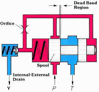
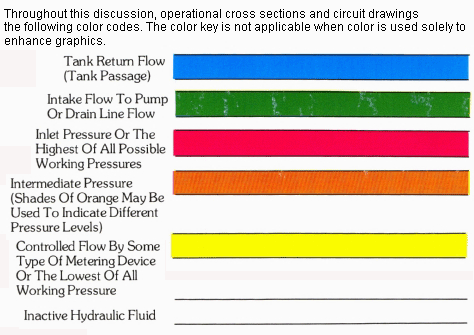
(See Color code legend for above image)
In reference to the operational cross section, the spool must first move through the deadband region before pressure opens to tank. This makes the spool design considerably slower than the poppet, since a poppet begins opening with the first increment of motion. Another detriment to the response time of a spool design is the high mass of the spool as compared to the poppet. Since all reliefs respond to pressure in a small portion of a second, the poppet or spool must undergo drastic acceleration and deceleration forces. Acceleration and deceleration occur as the moving member goes from rest, in the closed position, to a stable opening in the dynamic position. Of course, any reduction in mass greatly improves the response characteristics of the valve. Consequently, with spool reliefs, if the pilot circuit is orificed large enough to give good opening response, the physical overshoot of the spool during deceleration to the dynamic open position requires a longer time period to achieve stability. The optimal compromise is an overall response time of approximately 150 milliseconds.
Likewise, the overshoot characteristics of a relief valve are related to spool (or poppet) stroke as compared to valve opening. When it comes time to relieve oil, pressure can build to very high values almost instantaneously if the oil has nowhere to go. With spool designs, the pressure builds to the point where the pilot valve opens and creates the imbalance on the spool. Also, this imbalance must be high enough to achieve acceleration of the spool mass. The problem is that during the first moments of acceleration, the spool movement provides no opening. Since there is nowhere for the pump supply to go, pressure builds instantaneously to a high value. In other words, even if the spool mechanically responds quickly to increasing pressure, little or no opening during the initial response period shows up as a poor over shoot characteristic of the valve.
Finally, the life expectancy of spool type reliefs is very susceptible to contamination. In any relief, oil passes to tank at extremely high velocities. Contaminants in the oil, traveling at these high velocities, have a sandblasting effect on the exposed steel surfaces. The close tolerances on the large land areas of a spool design are more susceptible to damage and subsequent seizure than is the line contact area of a poppet. When exposed to systems with the same level of contaminants, the spool relief will either seize or leak excessively much sooner than a poppet design.
BALANCE PISTON—POPPET DESIGN
As shown in the cross-sectional drawing, you will notice that pressure is blocked from tank much like a check valve checks reverse free flow. In other words, when the valve opens, the flow of oil is around the poppet towards the seat. The term “balanced piston” comes from the fact that, when the valve is closed, there are equal areas exposed above and below the control piston. The differential force holding the piston closed in the static condition is only that of the light spring. The advantage this design offers over the spool type relief is that flow to tank is established immediately upon piston movement. Consequently, overshoot is limited to an average of 350 to 450 PSI.
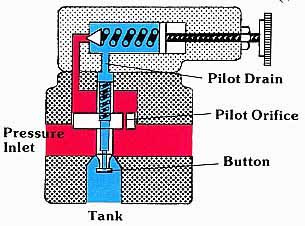
Above:
(See Color code legend for
above image)
Although the response of a balance piston-poppet relief is better than that of a spool type relief, the mass of the relatively large piston and poppet assembly is not much less than that of a spool. Consequently, the response time, from the time the valve first cracks to the time it reaches a stable opening, is more or less limited by the same factors that limit the spool design. Typical response characteristics for these designs range between 95 and 135 milliseconds.
One of the major disadvantages of a balanced piston-poppet relief is that it displays relatively bad pressure override characteristics. In this design, the poppet is inherently un stable, since a larger area is exposed to pressure when the poppet opens. As in the direct operated differential piston, a button is machined on the nose of the poppet. This button captures the hydrodynamic force as a force tending to close the valve. Of course, the higher the flow to tank, the higher the closing force; hence, the higher the pressure required to keep the valve open.
Of final concern is the fact that valves of this design can often generate noise in their tank port. The reason for this is the convergent flow to tank. These high velocities in a convergent path create an enormous amount of turbulence. This is especially true when you consider that the button is immersed in this flow stream creating even more of a disturbance.
CARTRIDGE POPPET DESIGN
The operational cross section shows that the cartridge unit consists of a small low mass poppet which offers a large flow area with minimum stroke. These design features allow the relief function to be performed quickly and quietly. Forces on the poppet are always in balance at any flow rate. Because of this, the valve is not only inherently stable, but it also operates with minimal pressure override. Likewise, the cart ridge design offers better serviceability and flexibility in mounting style that is not possible with parts and body construction.
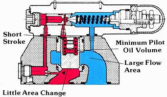
Above: (See Color code legend for
above image)
In consideration of the cartridge’s response characteristics, we said earlier that response is directly related to stroke vs. opening area. The short stroke means that very little oil has to be relieved by the pilot as the poppet moves upwards from its fully closed to its fully open position. Also, the low poppet mass means that movement occurs with a very minute decay in pressure in the pilot section. Low poppet mass, short pop pet stroke, and minimum oil displacement in the pilot section, allow the cartridge poppet to respond in the 50 or 60 millisecond range. This is actually faster than most direct operated valves.
Since the poppet provides a large flow path with its first increment of motion, overshoot is very low and of very short duration. Although overshoot is higher at lower operating pressures, the average overshoot is only 8 per cent of set pressure. This means that at 3000 PSI, the maximum pressure spike is in the neighborhood of 3250 PSI.
Another advantage to this design is that there is an in significant change in effective area between the open and closed position of the valve. Consequently, the forces tending to open and close the poppet are always in balance and not affected by flow. The typical valve reseats within 30 PSI of its cracking pressure, and is inherently stable throughout the entire flow range. Likewise, minimum compression of the light spring force, and a poppet design which is virtually unaffected by flow, result in a minimum pressure override.
Finally, the cartridge poppet is extremely quiet in performing its relief function. This is a result of the fact that the flow passage to tank is not only large, but it also creates a 360° divergent flow stream. The potential energy in the pressurized fluid is dissipated quickly and quietly.
| Top of Page | PREV.: Pilot-Operated Pressure Relief Valves | NEXT: Different Mounting Configurations | Home |