| PREV.: How Important are the Valve’s Pressure Override Characteristics? | NEXT: Pilot-Operated Pressure Relief-Valves | Article Index | Home |
AMAZON multi-meters discounts AMAZON oscilloscope discounts Direct acting (operated) reliefs are valves in which the spring force directly opposes the hydraulic pressure force. It stands to reason that a given spring constant can only be optimum for a given pressure level. Therefore, most direct operated valves have several spring options to cover the different operating pressure ranges. The spring constant has varying effects on the valve’s operating characteristics, which are more or less related directly to the actual valve design. Under the worst conditions, the relief can have a very narrow adjustability range due to the spring constant’s influence on pressure versus flow characteristics, hysteresis, and stability. With other designs, the only real effect is on sensitivity of adjustment. In the family of direct operated valves, several designs are offered by various manufacturers. We now wish to study the intended use and operation of the most popular designs. |
BALL-TYPE RELIEF
Although this is the simplest in design, the ball relief valve is probably the least desirable. Its disadvantage is that it can only handle small flows (usually less than 3 GPM) before it becomes noisy. The noise is developed when the ball lifts from its seat and begins to chatter in the flow stream. Of course, the higher the flow, the more unstable the ball becomes. The instability of the ball shows up in bad pressure fluctuations in the valve’s performance characteristics. Therefore, its use should be limited to infrequent duty safety relief, thermal expansion relief, or remote pilot for a pilot operated pressure control.
(See Color code legend for above image)
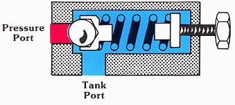
POPPET STYLE RELIEFS
The simple poppet design has operating characteristics similar to those of the ball design. This design, however, is somewhat more stable, since the cone has a tendency to center itself in the flow stream, where the ball is more likely to roll on top of the stream of fluid. Because it is somewhat more stable, it can handle slightly larger flows without excessive noise. Pressure override with a poppet style relief is as undesirable as it is with the ball style relief. Its use should, therefore, be limited to infrequent duty or for remote piloting in low flow applications.
(See Color code legend for above image)
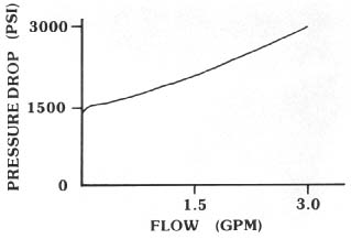
Above: Typical Pressure vs. Flow Characteristics for a Simple Poppet
or Ball Style Relief.
GUIDED POPPET DESIGN
By guiding the poppet with a close tolerance fit, direct operated reliefs can technically be made to pass considerably more fluid without the instability problems associated with unguided models. A problem arises in mechanically guiding the poppet because the poppet guide blocks the free flow of fluid to tank once the valve opens. To overcome this problem, with most designs, the oil flows to tank through cross drillings in the poppet. This, of course, is a restriction which limits the maximum flow capacity of the valve. Although stability and noise are improved, this design still has a problem in overcoming pressure override with in creased flow. In general, precautions must be taken not to exceed the recommended flow, since high velocities through the cross drillings in the poppet can cause a severe whistle.
Although this design is basically intended for use as a remote pilot control, it can also be used as a main system relief in low powered systems. Before selecting this design, however, you should consider the effects pressure override will have on satisfactory system operations.

(See Color code legend for above image)
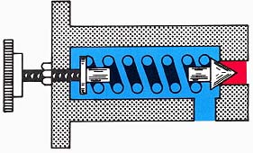
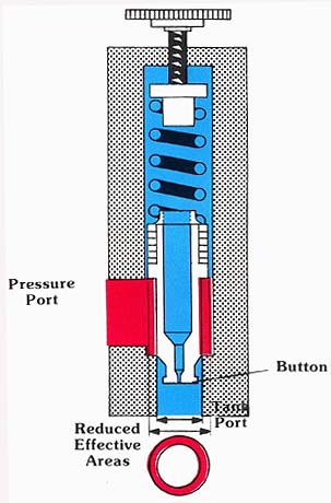
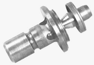
DIFFERENTIAL PISTON
We said before that the poppet area exposed to system pressure creates a force which is opposed by a spring. If we were able to design a valve in which the exposed poppet area was only a small percentage of the final open flow area, we could have a direct operated relief capable of handling larger flows with a relatively lighter spring than a basic poppet design. This is exactly the principle used in the differential piston design. The lighter spring has a lower spring constant. Hence, pressure override due to length of compression can be reduced.
You will notice in the cross-sectional illustration, that by locating the pressure port on the same side of the seat as the poppet, the nose of the poppet, which extends through the seat, is exposed to atmospheric tank pressure rather than to system pressure. The only effective area for system pressure to act upon is the ring area, which has an ID of the seat, and the OD of the sliding fit of the poppet guide. As you can see in the figure, the area can be easily changed by proper pop pet design to optimize the required spring force to balance the smaller hydraulic force.
(See Color code legend for above image)
The only major problem with most differential piston designs is that once they open, the nose of the poppet enters the pressurized flow stream. A drastic increase in the effective area can occur, and the spring can no longer close the valve. To overcome this problem, the nose of the poppet has a but ton machined on it, which disturbs the flow path to the tank. This captures the velocity head of the fluid, which assists in closing the valve. Unfortunately, the poppet nose restricts the effective flow area to tank. This orificing can have a detrimental effect on the pressure override characteristics of the valve. Nevertheless, the advantages offered by the differential piston are in some way incorporated in most high pressure, high flow, direct operated designs.
THE GUIDED POPPET WITH DYNAMIC ASSIST
This direct operated relief valve overcomes the typical performance problems which are normally associated with direct operated designs. As mentioned, the problems include bad pressure override, noise, instability and a narrow range of adjustability. Let us now consider each problem individually, and the design feature incorporated to overcome this problem.
(See Color code legend for above image)
Pressure Override
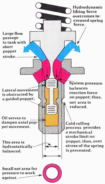
We know that with direct-operated reliefs, pressure override occurs because of increased spring force with additional compression, loss of effective area with poppet opening, and additional pressure drop due to increasing flows. All of these are physical facts which exist, and, therefore, must be dealt with to give good performance specification. With this guided poppet design, a wing is incorporated on the poppet just above the seat. The advantage of the wing is that a hydrodynamic lifting force, similar to the aerodynamic force which lifts an airplane wing, helps open the poppet after cracking pressure has been reached. The wing area and shape can be optimized so that the valve uses the kinetic energy, or momentum of the fluid at high velocity, to counteract exactly the increased spring force and the loss of area. This results in a perfectly flat pressure vs. flow curve.
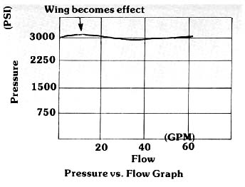
Above: Pressure vs. Flow graph
Noise
Two basic noise generators in relief valves are poppet and spring chatter and high velocity oil. As mentioned previously, we can mechanically guide the poppet. However, when this is done, the mechanical means incorporated can cause obstructions in the free flow path to tank. By placing a “nose guide” on the high pressure side of the seat, we take the guiding mechanism out of the oil path to tank, allowing a 360 degrees divergent flow path as formed by the wing. High velocity through cross drillings is overcome, eliminating the whistle. Since the poppet is not allowed to move laterally, spring and poppet chatter is also eliminated. Consequently, the relieving function is quiet at any flow rate.
Stability
If you ever tried to hold your thumb over the stream of water coming from the end of a garden hose, you can understand how erratic the poppet position can be in the stream of oil. Each lateral or vertical motion of the poppet, no matter how small, compresses or relaxes the spring. This rapid changing of spring position shows up in instability on the pressure gauge. Guiding the poppet eliminates the possibility of lateral movement and helps the stability of the relief. However, we must also concern ourselves with erratic axial movement.
The nose guide not only guides the poppet, but also serves as a shock absorber. System pressure fills the can in which the nose guide rides. Small metering notches on the guiding lands restricts the oil transfer from one side of the land to the other. Since the oil must transfer for poppet motion to occur, erratic axial motion of the poppet is dampened.
Adjustability Range
Although the guided poppet with dynamic assist does not conform to the basic design of differential piston relief valves, you can see from the diagram that a hydrostatic balancing force exists which greatly reduces the effective area which is exposed to pressure.
Since system pressure works only on a small area, the spring can be much lighter than that needed to balance the force created by the full area of the poppet. A lighter spring means fewer pounds per inch compression (spring constant k), and, therefore, a larger adjustability range. In actual practice, the higher pressure relief valves can be adjusted quite low without adversely effecting performance. A 3000 PSI spring can easily be adjusted from 300 to 400 PSI with only an expected loss of adjustment accuracy.
(See Color code legend for above image)
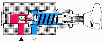
SYMBOLS
The direct acting relief valve is represented by a square. The pressure sensing line (pilot line) is represented by the dash line, and is directly opposed by the spring force. The arrow position shows that the valve remains closed until the pressure force overcomes the spring force and pushes the arrow over so that the flow is directed to tank.
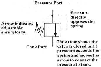
Above: Pressure Port: Arrow indicates adjustable spring force.
Tank Port Pressure directly opposes the spring. The arrow shows the valve
is closed until pressure exceeds the spring and moves the arrow to connect
the pressure to tank.