| PREV.: Hi-Low Unloading Valve | NEXT: Symbols | Article Index | Home |
AMAZON multi-meters discounts AMAZON oscilloscope discounts The accumulator unloading valve has been designed specifically for use in accumulator circuits. Its design provides three functions. It limits maximum system pressure, unloads the pump to tank when the accumulator reaches the desired pressure, and it reloads the pump to bring the accumulator up to full charge after a predetermined minimum pressure has been reached. To better understand the operation of this valve Google “accumulators”. |
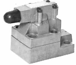
Above: An accumulator unloading valve
It is sufficient, for purposes of this section, to say that an accumulator stores a given volume of oil under pressure. Likewise, at a relatively low pressure, the accumulator stores less fluid than it does at full system pressure. Actually, the oil volume available from an accumulator is determined by subtracting the oil volume held at minimum operating pressure from the quantity of oil stored at maximum system pressure. This differential volume is discharged by the accumulator as system pressure drops from maximum to minimum. Of course, the time period during which the drop in pressure occurs establishes the flow rate available from the accumulator.
Remember:
Flow = Volume / Time
When used with a fixed displacement pump, the accumulator unloading valve performs both a relief and an unloading function. The valve consists of a cartridge poppet pilot operated relief valve, an isolating full flow check valve, and an unloading piston, which overrides the pilot relief function. Let us now consider the various operating conditions of this valve.
CHARGING THE ACCUMULATOR
The operational cross-section shows that this valve has three working ports: a pump inlet, a system connection, and a tank return.
The pump’s outlet is connected directly to the pressure port of this valve, so that all the pump flow must pass through the valve before entering the system. Of course, the tank port is connected directly to the hydraulic reservoir. If you want to pass the return flow through filters or heat exchangers, you should use an external drain for the spring chamber of the pilot.
Assuming that the pilot spring seats the pilot poppet, the main poppet is also closed, due to the hydraulic pressure balance and the light spring force. The valve delivers flow to the system over the isolating check valve, which in turn charges the accumulator as pressure in the system increases. You will notice that as long as there is flow, a higher pressure exists on the right hand area of the unloading piston than on the left, due to the pressure drop across the isolating check valve. The unloading piston is held in the left most position, and has no effect on the relieving function.

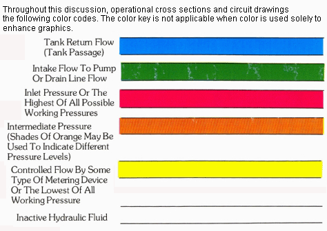
Above: Charging the Accumulator. (See Color
code legend for above
image)
RELIEVING AND UNLOADING OF THE PUMP
When the accumulator has reached its desired charge, system pressure unseats the pilot relief, which causes a decay in pressure above the main poppet. At the same time, pressure is lost on the right hand area of the unloading piston, so that pressure in the system from the accumulator holds the unloading piston against the nose of the pilot pop pet, keeping it unseated. The moment the main poppet opens, a pressure loss at the inlet of the check valve causes it to close, thus isolating the pump from the rest of the system. Under these conditions, the pump circulates oil freely to tank while pressure in the system is maintained by the accumulator.
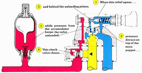
Above: Relieving and Unloading of the Pump. (See
Color code legend for above
image)
RELOADING OF THE PUMP
The whole purpose of an accumulator unloading valve is to prevent the pump from being reloaded the moment a slight decay in system pressure occurs. This is exactly the reason a standard unloading valve cannot be used in an accumulator application. That is, with a standard unloading valve, the small pressure differential between open and closed positions would set up a rapid cycling of the pump between the loaded and unloaded conditions. To overcome this problem, the pilot head of an accumulator unloading valve is designed with differential effective areas between the pilot relief and the unloading piston.
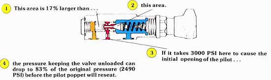
(See Color code legend for above image)
The illustration above shows how the accumulator unloading valve allows system pressure to fall to a predetermined minimum value before reloading the pump. Since the effective area of the pilot poppet is smaller than that of the unloading piston, a higher pressure is needed to initially move the pilot poppet against the spring force. Once the right hand area of the unloading piston is vented over the opened pilot poppet, system pressure becomes effective on the larger area of the unloading piston. Of course, the larger area means more available force, so that we can keep the pilot poppet unseated with a somewhat lower pressure. The area ratio is usually in the neighborhood of 17%.
PRECAUTIONS
The function of the accumulator unloading valve should not be confused with that of an accumulator safety valve. Once the accumulator is charged, the unloading valve has no means of bleeding the accumulator charge to tank if the system is shut down. Likewise, a fully charged accumulator is not protected from over pressure due to increased load or thermal expansion. The accumulator unloading valve only provides pressure protection in regard to the pump’s capability to pressurize the system.
SOLENOID VENTING OPTION
Like the solenoid venting feature for pilot operated reliefs, a directional control can be added to the pilot section of the accumulator charging valve. An electrical signal can override the unloading of the pump, as was already shown in the discussion of pilot operated reliefs.
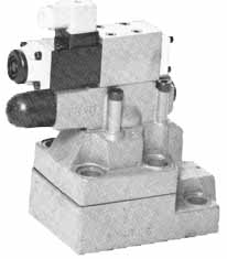
Above: Accumulator Unloading Valve with Solenoid Venting
| Top of Page | PREV.: Hi-Low Unloading Valve | NEXT: Symbols | Home |