Hi-Low Unloading Valve

PREV.: Unloading Valves NEXT: Accumulator Unloading Valves Article Index Home


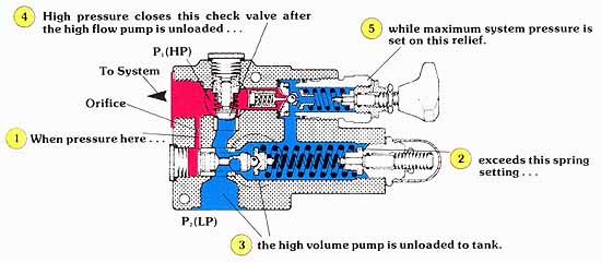
AMAZON multi-meters discounts AMAZON oscilloscope discounts

We have just shown how an unloading valve can be piped into a system to provide unloading of the high volume pump. To complete this hi-low circuit, it was necessary to in corporate two separate components, namely, an isolating check valve and a high pressure low flow relief.

Assuming that the selected pumps and system requirements fall within the performance capabilities of the valve, multiple components and related piping can be replaced by a single component. As shown in the cross-sectional illustration, this valve package consists of a direct operated unloading valve, a high pressure relief, and an isolating check valve. Pipe connections to the valve include high volume pump, high pressure pump, system and tank return.


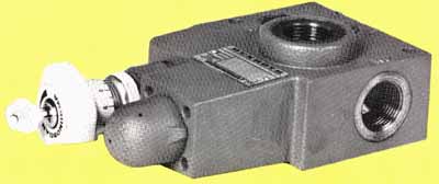
Above: A Rexroth Hi-Low Unloading Valve. Cross-section diagram is below.


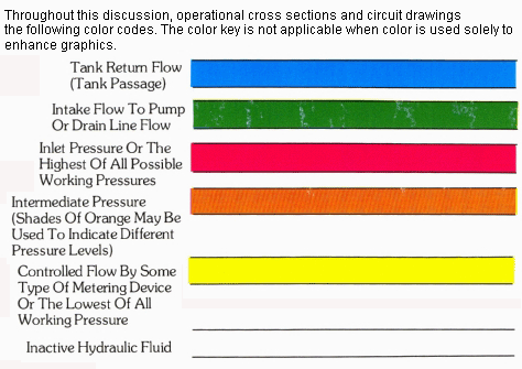
(See Color code legend for above image)

Hydraulic line color-coded legend. Used in schemaics.

Top of Page PREV.: Unloading Valves NEXT: Accumulator Unloading Valves Home

Wednesday, March 4, 2020 10:04

Make-Up Check Port Relief Valve Directional Control From Pump From Pump Directional Control Fly wheel Hydraulic Motor Crossport Reliefs X port Y drain P1 P2 Tank 1. When the pilot relief opens... 2. a constant pilot flow is established... 3. by this pressure compensated flow control. 4. The pressure in the pilot circuit determines... 5. the outlet pressure on this area needed to close the main spool. 6. The main spool orifices flow to the secondary system, which keeps outlet pressure in equilibrium with pilot pressure. Main System Flow (GPM) Inlet to outlet pressure: 3000 PSI delta P, 1500 PSI delta P Pilot Flow in^3/Min 3. This feeds back an inaccurate downstream pressure... 4. and lessens the pilot oil flow. 2. creates turbulence downstream of the main control spool. 1. A high flow rate… Pressure Compensated Flow Control Metered Pilot Flow Pilot Relief Over Pressure Relief Protection Drain Port High Pressure Inlet Reduced Pressure Outlet Gauge Port 1. When this pilot relief is closed... 2. the pressure above the control spool is the same... 5. Consequently, the main control spool is held in the WIDE OPEN POSITION, since there is a larger opening force than closing force. 4. The pressure at the outlet is only slightly lower than that at the inlet because of pressure drop due to flow. 3. as the pressure at the inlet, since the pilot system is static. 1. When the secondary system become static... 2. leakage by the main control spool… 3. could cause downstream pressure to equalize... 5. However, this relief opens when pressure builds to 45 PSI above that set on the pilot... 4. with inlet pressure... 6. which limits the pressure build-up downstream of the valve. P2 (LP) P1 (HP) Orifice To System 2. exceeds this spring setting... 5. while maximum system pressure is set on this relief. 3. the high volume pump is unloaded to tank. 4. High pressure closes this check valve after the high flow pump is unloaded... 1. When pressure here…