| PREV.: Overcenter Counterbalance Valves | NEXT: Hi-Low Unloading Valve | Article Index | Home |
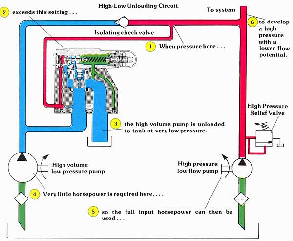
AMAZON multi-meters discounts AMAZON oscilloscope discounts Unloading valves are used in hydraulic circuits to offer high speeds up to a pre-determined pressure level. At valve set ting, a remote pressure signal unloads part of the original flow source to tank. A prime example of an unloading application is a two pump “hi-low” unloading circuit. In many applications, where high speed and high force are not needed simultaneously, you can achieve a considerable savings of installed horsepower by selecting a two pump system. The first pump supplies high flow at lower operating pressures, and the second pump offers higher pressures, but at a lower flow. Remember that: (Flow x Pressure) / 1714 = HP You can see that, at low pressure and high flow, the calculated horsepower can be the same as it would be if the system were operating at high pressure and low flow. Let us now take a look at a circuit which accomplishes this task. |
Above: (See
Color code legend for
above image)
As shown in the example, a multifunction valve with external pilot and internal drain can be used to unload the high volume pump. As long as the system is operating at a pressure lower than that set on the unloading valve, the valve remains closed. Under these conditions, the output of the high volume pump supplements the output of the small pump, and the system operates at full speed. As the system offers an increased resistance to flow, pressure builds on the outlet of both pumps, and on the pilot spool in the unloading valve. When the pressure is high enough to move the pilot spool against the spring setting, the output of the high volume pump is connected to tank. Whenever the main system is operating at a pressure of approximately 100 PSI over the setting of the unloading valve, the output of the high volume pump is circulated back to tank at minimum pressure. If, for some reason, the system pressure drops below the setting of the unloading valve, the circuit automatically shifts itself into high speed operation.
(See Color code legend for above image)
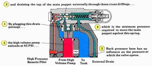
REMOTE DRAIN OPTION FOR PILOT OPERATED UNLOADING VALVES
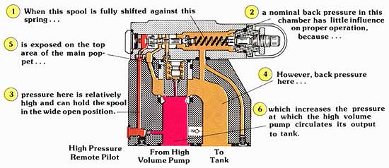
Since the outlet of the unloading valve is connected to tank satisfactory opera can normally be achieved by internally draining the valve However, if it becomes desirable to circulate the output of the high volume pump through filters and heat exchangers, the resistance to flow added by these components can adversely affect the efficiency of the system. Let us now take a closer look at a pilot operated unloading valve, and how it is affected by back pressure at its outlet.
In unloading applications, the efficiency of the system de pends on the minimum pressure at which the high volume pump circulates oil. If, for instance, we were to unload a 100 GPM pump at 50 PSI, our horsepower to drive the pump would be a little less than 3 HP. The same pump, with a 200 PSI resistance to flow in the unloaded condition, would require almost 12 HP to circulate the oil. This not only draws unnecessary power from the prime mover, but, in turn, it generates an equal amount of heat. A slight modification to the pilot spool of a standard multifunction pressure control optimizes the minimum pressure at which the valve unloads its pump.
(See Color code legend for above image)
| Top of Page | PREV.: Overcenter Counterbalance Valves | NEXT: Hi-Low Unloading Valve | Home |